INSTRUCTION MANUAL 3 CCD CAMERA IK-TF5C For Customer Use Enter below the Serial No. which is located on the bottom of the cabinet. Retain this information for future reference. Model No.: IK-TF5C Serial No.: FCC NOTICE This equipment has been tested and found to comply with the limits for a Class A digital device, pursuant to Part 15 of the FCC Rules. These limits are designed to provide reasonable protection against harmful interference when the equipment is operated in a commercial environment.
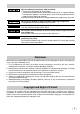
SAFETY PRECAUTIONS Safety icons This manual contains safety instructions that must be observed in order to avoid potential hazards that could result in personal injuries, damage to your equipment, or loss of data. These safety cautions have been classified according to the seriousness of the risk, and the icons highlight these instructions as follows: Indicates a potentially hazardous situation which, if not avoided, could result in death or serious injury.
Note the following instructions when installing. • Do not cover the product by any material. • Do not put the product on an Inflammable material such as carpet or blanket. • Do not put the product in a narrow space, since the heat generated from the product may be difficult to emanate. If you do not follow the above, the heat generated by the product may cause fire. Do not put the product in direct sunshine and/or high temperature. The temperature inside the product may cause fire.
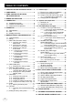
TABLE OF CONTENTS 1. CAUTIONS ON USE AND INSTALLATION ..... 5 7. 3 External Sync ............................................ 22 2. COMPONENTS ................................................ 5 ( 1 ) External sync signal input conditions ...... 22 ( 2 ) External sync frequency range ............... 22 ( 3 ) Using the unit with external sync signal .. 23 3. ITEMS CONTROLLED BY USING ON SCREEN DISPLAY .................................... 6 4. NAMES AND FUNCTIONS .............................. 7 5.
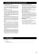
1. CAUTIONS ON USE AND INSTALLATION • Carefully handle the units. • Do not drop, or give a strong shock or vibration to the camera. This may cause problems. Treat the camera cables carefully to prevent cable problems, such as cable breakdown and loosened connections. • Do not shoot intense light. If there is an intense light at a location on the screen such as a spot light, a blooming and smearing may occur. When intense light enters, vertical stripes may appear on the screen.
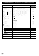
3. ITEMS CONTROLLED BY USING ON SCREEN DISPLAY Item Available selections MODE E. TRG MANU speed Electronic shutter Gain White balance Process Sync Option 6 Preset value (Factory setting) MANU, SS, E. TRG 1P SNR, 1P SR, PW SNR, PW SR, RR OFF, 1/100s, 1/250s, 1/500s, 1/1000s, 1/2000s, 1/4000s, 1/10000s, 1/25000s, 1/50000s, 1/1000000s Syncro. Partial read OFF 1H/525H~524H/525H, OFF, 2FRM~512FRM scan.
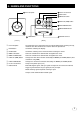
4. NAMES AND FUNCTIONS 8 DC IN 12V terminal 1 Prism faceplate 2 DISP button 4 MENU UP button (AWB) 6 DATA UP (AWB) button DISP MENU DATA DC IN 12V PAGE 7 DATA DOWN button 5 MENU DOWN button 9 DIGITAL terminal 3 PAGE button [ Front ] 1 Prism faceplate 2 DISP button 3 PAGE button [ Rear ] The protection cap is attached on the lens mount portion. After removing the cap, mount the lens. Be careful not to scratch or touch the optical area. Used when switching the display.
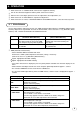
5. CONNECTION 5. 1 Standard Connection Lens Cable (not included) IK-TF5C DC IN 12V Frame grabber board, image process equipment etc. Less than 4 mm DC power supply Monitor 5. 2 Cautions on Connection • When connecting the camera cables, unplug the power source of the camera and the other equipment connected. • We suggest using a C mount lens made for a 3CCD camera. When using another lens, the best camera performance of this camera may not be obtained.
6. OPERATION 1 Refer to the item " 5. CONNECTION", connect each equipment correctly. 2 Turn on the connected equipment and the power source of the camera. 3 Point the lens at the object, operate the lens iris adjustment, focus adjustment, etc.. 4 Refer to the item "6.1 White Balance", operate the adjustment. 5 Refer to the items "6.2 Gain, 7. MODE SETTING BY ON SCREEN DISPLAY", select the necessary items. 6.
Result displayed AWB NG NOT AVAILABLE AWB NG Meaning Automatic white balance adjustment cannot be performed because the shutter speed mode is E.TRG mode. Automatic white balance adjustment cannot be performed for other reasons. Such as no white area is included in an object, etc. 2 MANU (Manual white balance) • Set the MODE to MANU on the WHT BAL menu. (Refer to the item "7.2 (3) WHT BAL (white balance)".
7. MODE SETTING BY ON SCREEN DISPLAY Various settings can be controlled on the unit by using the on screen menu displayed on the monitor. The contents once set are memorized even if the power source is turned off, so it is unnecessary to set again when using the unit next time. When the setting is performed, select the menu of the item to be set. 7. 1 Using the Menus When the power is turned on, the normal screen showing only the video signal appears.
7. 2 Menus • Select the menu to change the setting by referring the item "7.1 Using the Menus".) • When the [MENU UP], [MENU DOWN] buttons are pushed, the "→" on the screen moves up and down. Move the "→" to the item to change. Note: When performing the mode setting in the menu display while selecting ON in "PART" (refer to page 30) and E.TRG in "MODE", the display shows normal mode and then the camera returns the setting mode.
(1. 2) Changing each setting in SS (synchro. scan) mode Move up down By pushing MENU UP, DOWN Set by pushing DATA UP, DOWN • Sutter mode MANU, SS, E.TRG -- SHUTTER -MODE SS PART SS OFF OFF • Synchro. scanning setting OFF : 1H/525H↔524H/525H↔OFF↔2FRM↔512FRM 120fps, E.120fps : 1H/262H↔261H/262H↔OFF↔2FRM↔512FRM 180fps, E.180fps : 1H/175H↔174H/175H↔OFF↔2FRM↔512FRM • Partial scanning switch OFF/120fps/180fps/E.120fps/E.
(1. 3) Changing each setting in E.TRG mode The E.TRG has five modes; 1P SNR, 1P SR, PW SNR, PW SR, RR. First set the "→" to MODE and select E. TRG, then set the "→" to E.TRG and select the desired E.TRG mode. (1. 3. 1) Changing each setting in 1P SNR mode Move up down By pushing MENU UP, DOWN Set by pushing DATA UP, DOWN • Sutter mode MANU, SS, E.TRG -- SHUTTER -MODE E.TRG TRG.P EXP. PART E.TRG 1P SNR 16ms OFF • E.
(1. 3. 2) Changing each setting in 1P SR mode Move up down By pushing MENU UP, DOWN Set by pushing DATA UP, DOWN • Sutter mode MANU, SS, E.TRG -- SHUTTER -MODE E.TRG TRG.P EXP. PART E.TRG 1P SR 16ms OFF • E.TRG mode 1P SNR, 1P SR, PW SNR, PW SR, RR • Input trigger pulse setting at 1P SNR and 1P SR Input trigger pulse : positive polarity Input trigger pulse : negative polarity • Exposure time setting at 1P SNR and 1P SR 0.01 ms 0.02 ms 0.4 ms 1 ms 16 ms 0.01 ms 0.02 ms 0.
(1. 3. 3) Changing each setting in PW SNR mode Move up down By pushing MENU UP, DOWN Set by pushing DATA UP, DOWN • Sutter mode MANU, SS, E.TRG -- SHUTTER -MODE E.TRG TRG.P PART E.TRG PW SNR OFF • E.TRG mode 1P SNR, 1P SR, PW SNR, PW SR, RR • Input trigger pulse setting at PW SNR and PW SR Input trigger pulse : positive polarity Input trigger pulse : negative polarity • Partial scanning switch OFF/120fps/180fps/E.120fps/E.180fps
(1. 3. 4) Changing each setting in PW SR mode Move up down By pushing MENU UP, DOWN Set by pushing DATA UP, DOWN • Sutter mode MANU, SS, E.TRG -- SHUTTER -MODE E.TRG TRG.P PART E.TRG PW SR OFF • E.TRG mode 1P SNR, 1P SR, PW SNR, PW SR, RR • Input trigger pulse setting at PW SNR and PW SR Input trigger pulse : positive polarity Input trigger pulse : negative polarity • Partial scanning switch OFF/120fps/180fps/E.120fps/E.180fps
(1. 3. 5) Changing each setting in RR mode Move up down By pushing MENU UP, DOWN Set by pushing DATA UP, DOWN • Sutter mode MANU, SS, E.TRG -- SHUTTER -MODE E.TRG PART E.TRG RR OFF • E.TRG mode 1P SNR, 1P SR, PW SNR, PW SR, RR • Partial scanning switch OFF/120fps/180fps/E.120fps/E.180fps (a) Changing the partial scanning setting 1 Set the "→" to PART by pushing [MENU UP], [MENU DOWN] buttons. 2 Select either OFF/120fps/180fps/E.120fps/E.
( 3 ) WHT BAL (White balance) WHT BAL has two modes; AWB, MANU. Set the "→" to MODE, push the [DATA UP], [DATA DOWN], and select mode among AWB, MANU. (3. 1) Changing each setting in AWB (Automatic White Balance) mode Move up down By pushing MENU UP, DOWN Set by pushing DATA UP, DOWN -- WHT BAL -MODE C.TEMP AWB 3200 • White balance mode setting (AWB, MANU) • Color temperature setting 3200, 5600 (a) Changing color temperature setting 1 Set the "→" to C.TEMP by pushing [MENU UP], [MENU DOWN] buttons.
( 4 ) PROCESS Move up down By pushing MENU UP, DOWN Set by pushing DATA UP, DOWN -- PROCESS -M.PED R.PED B.PED SHAD. MANU • Master pedestal adjustment -64 to 64 0 0 0 MANU 0 • R pedestal adjustment -64 to 64 • B pedestal adjustment -64 to 64 • Shading mode setting MANU/OFF • Manual shading adjustment -128 to 127 (4. 1) Changing master pedestal 1 Set the "→" to M. PED by pushing [MENU UP], [MENU DOWN] buttons. 2 Set the master pedestal by pushing [DATA UP], [DATA DOWN] buttons. (4.
( 5 ) SYNC When an external sync signal is input, the display menu changes from INT (internal sync) to EXT (external sync) automatically. Move up down By pushing MENU UP, DOWN Set by pushing DATA UP, DOWN -- SYNC -• Sync system display MODE EXT H PHASE 0 • H PHASE -100 to 100 (5. 1) Adjusting horizontal phase 1 Set the "→" to H PHASE by pushing [MENU UP], [MENU DOWN] buttons. 2 Adjust the horizontal phase by pushing [DATA UP], [DATA DOWN] buttons. ( 6 ) OPTION (6.
( 7 ) Setting to factory setting status All the settings can be returned to the factory default status (preset status). (1) If characters are displayed on the screen, press the [DISP] button to disable the character display. (2) Push [MENU DOWN] and [DATA DOWN] buttons simultaneously for approx. 1 second. (3) The preset operation starts. When the preset operation finishes, the character PRESET OK is displayed for approx. 1 second. 7.
( 3 ) Using the unit with external sync signal When adjusting H (horizontal) phase refer to the item "7.2 (5) (5.1) Adjusting horizontal phase". External Sync. signal (3. 1) H (horizontal) phase adjustment Observe the external sync signal and the LVAL signal output waveform of the unit with a dual trace oscilloscope, and adjust H phase so that the H phases match. Match the phase. LVAL signal output 7. 4 Synchro.
7. 5 EXT TRIG (External trigger) Charge begins to accumulate after the trigger input to CC1 of the DIGITAL terminal, and 1 frame images are output. There are five modes: 1P SNR, 1P SR, PW SNR, PW SR, RR. ( 1 ) 1P SNR (1 Pulse Trigger Sync Non Reset) Charge begins to accumulate after the trigger input to CC1 of the DIGITAL terminal, and 1 frame images are output. (1.
(1. 2) 1 Pulse Trigger SYNC-NON RESET Picture Output Timing (at Time of Internal Sync) Negative polarity mode Trigger*1 Positive polarity mode About 1 µs Exposure period*2 Exposure period*2 (Internal VD)*3 RGB data (video interval image) FVAL LVAL, DVAL 20H (Partial scanning OFF) 18H (Partial scanning 120fps) 23H (Partial scanning 180fps) *1: Externally input signal *2: Exposure time is determined by the setting of "7. 2 (1.3) Changing each setting in E.TRG mode".
( 2 ) 1P SR (1 Pulse Trigger Sync Reset) Charge begins to accumulate after the trigger input to CC1 of the DIGITAL terminal, the vertical sync signal is reset and frame images are output. (2.
( 3 ) PW SNR (Pulse width trigger SYNC-NON RESET) The trigger input to CC1 of the DIGITAL terminal develops 1 frame images. (3.
(3.
( 4 ) PW SR (Pulse width trigger SYNC-RESET) The trigger input to the CC1 of the DIGITAL terminal develops 1 frame images. (4.
( 5 ) RR (Reset restart) Input of an external reset-restart signal (CC4 of the DIGITAL terminal: External VD input) permits one screen of information to be output at an arbitrary timing. (5. 1) Long Term Exposure When a sufficient sensitivity is not obtained with the normal operating conditions or capturing the trail of a moving subject is desired, the reset-restart function allows high-sensitivity images by extending the exposure time.
7. 6 Partial Read ( 1 ) Partial Scanning OFF (All pixels scanning) In this mode, all pixels independent signal from the DIGITAL connector is output each 1/60 second (Line order output). Video interval image 1/60s (525H) ( 2 ) Partial Scanning ON In this mode, the pixel signal of the vertical center portion from the DIGITAL connector is output. In the E.60fps or E.90fps mode, the partial scanning and the all pixels scanning can be switched by the DIGITAL terminal (CC2: partial scanning control signal).
8. INPUT OUTPUT SIGNAL SPECIFICATOINS ( 2 ) VD Input Specifications ( 1 ) HD Input Specifications 5H to 21H 2.0 µs to 5.0 µs ( 3 ) Trigger Pulse Specifications More than 2 µs (Positive polarity mode) More than 2 µs (Negative polarity mode) ( 6 ) External HD/VD Input Phase Specifications External HD rising edge 100 100 External HD Unit : Clock 1 clk=40.74 nsec Center The phase relationship of the external HD and VD should correspond to the center phase (i.e.
9. CCD OUTPUT WAVEFORM TIMING CHART ( 1 ) Horizontal Output Waveform Timing Chart One horizontal scan interval 780 clk (31.8 µs) LVAL, DVAL 132 clk (5.38µs) 31 clk 72 clk 40.7 ns 16 clk 2 clk CCD output signal 7 clk 4 Optical black Horizontal transfer Dummy clk portion stop interval pixels Horizontal blanking interval 132 clk Total effective pixels 659 clk Optical black portion Output video interval 648 clk (26.4 µs) (5.38 µs) RGB data Pixel Clock CLK=40.74nsec (24.
10. SPECIFICATIONS Power supply Power consumption Pick-up system Image sensor (Effective pixels) Scanning system Scan frequency Sync system Horizontal resolution Sensitivity Minimum illumination Lens mount Ambient temperature Ambient humidity Weight External dimension White balance Gain Output signal Sync signal output External sync input Interface Optional parts DC12V±10% Approx. 4.3W RGB, 3CCD 1/3inch All pixels CCD (Horizontal : 659pixels, Vertical : 494pixels) Progressive scan Horizontal : 31.
11. EXTERNAL APPEARANCE DIAGRAM Unit : mm [inch] 26 [1.02] 5 [0.20] 44 [1.73] 2-M3 Depth 3 6.3 [0.25] 78 [3.07] 12 [0.47] (AWB) DISP 44 [1.73] MENU DATA 8.2 [0.32] 22 [0.87] 34 [1.34] DC IN 12V PAGE 4.8 [0.19] 5 [0.20] 4-M3 Depth 3 2-M2 19.2 [0.76] 26 [1.02] 25 [0.98] 26 [1.02] 56 [2.20] 4-M2 Depth 3 25 [0.98] 25 [0.98] ∗ inch=mm/25.4 12.
LIMITED WARRANTY TOSHIBA CCD CAMERA Promptly register your product with Toshiba on-line at www.toshiba.com/taisisd. By registering your product you will be eligible for periodic updates, announcements, and special offers. You will have access to extended warranty options, upgrades (as applicable), useful tips, on-line troubleshooting, and the ability to schedule service on-line if necessary. The Imaging Systems Division of Toshiba America Information Systems, Inc.