TEC Thermal Printer B-450-QP SERIES Owner’s Manual Mode d’emploi Bedienungsanleitung Manual de instrucciones Gebruikershandleiding Manuale Utente
LIST OF STANDARDS OF CONFORMITY We, TOSHIBA TEC Corporation of 570 Ohito Ohito-Cho Tagata-Gun Shizuoka-Ken 4102392 Japan declare in our sole responsibility that the product: Bar Code Printer, B-450 Series to which this declaration relates is in conformity with the following standards under Low Voltage Directive 73/23/EEC and EMC Directive 89/336/EEC: Safety EMC : : : Harmonics : Voltage Fluctuations : EN 60 950 EN 55022 EN 50082-1 EN 61000-3-2 EN 61000-3-3 WARNING! This is a Class A product.
TEC Thermal Printer B-450-QP SERIES Owner’s Manual
ENGLISH VERSION EO1-33005 Safety Summary Safety Summary Personal safety in handling or maintaining the equipment is extremely important. Warnings and Cautions necessary for safe handling are included in this manual. All warnings and cautions contained in this manual should be read and understood before handling or maintaining the equipment. Do not attempt to effect repairs or modifications to this equipment.
ENGLISH VERSION EO1-33005 Safety Summary Disconnect the plug. Connect a grounding wire. If foreign objects (metal fragments, water, liquids) enter the machines, first turn off the power switches and disconnect the power cord plugs from the outlet, and then contact your authorized TOSHIBA TEC representative for assistance. Continued use of the machine in that condition may cause fire or electric shock. Disconnect the plug. When unplugging the power cords, be sure to hold and pull on the plug portion.
ENGLISH VERSION EO1-33005 TABLE OF CONTENTS Page 1. INTRODUCTION .............................................................................................. E1- 1 1.1 APPLICABLE MODEL .............................................................................. E1- 1 1.2 ACCESSORIES ........................................................................................ E1- 1 2. SPECIFICATIONS ............................................................................................ E2- 1 2.
1. INTRODUCTION ENGLISH VERSION EO1-33005 1.1 APPLICABLE MODEL 1. INTRODUCTION Thank you for choosing the TEC B-450 Series thermal/transfer printer. This new generation high performance high quality printer is equipped with the latest hardware including the newly developed high density (11.8 dot/mm, 300 dot/inch) print head. This allows very clear print at a maximum speed of 101.6 mm/sec. (4 inch/sec.). Other standard features include an external paper supply.
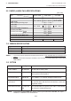
ENGLISH VERSION EO1-33005 2. SPECIFICATIONS 2.1 GENERAL SPECIFICATIONS 2. SPECIFICATIONS 2.1 GENERAL SPECIFICATIONS Model B-452-TS12-QP Item Supply voltage Power consumption Operating temperature Relative humidity Dimensions Weight 220 - 240V, 50Hz 0.41 A, 74 W maximum (standby: 0.15 A, 23.5 W maximum) 5˚C ~ 40˚C 25% ~ 85%RH (no condensation) 270 mm (width) x 245 mm (height) x 200 mm (depth), with Supply holder unit 410 mm (depth) 4.7 kg (without paper and ribbon) 2.
ENGLISH VERSION EO1-33005 2. SPECIFICATIONS 2.3 PAPER (LABEL/TAG) SPECIFICATIONS 2.3 PAPER (LABEL/TAG) SPECIFICATIONS [Unit: mm] Label dispensing mode Item Batch mode Span of one label/tag 15.0 ~ 999.0 Label length Width including backing paper Label width Gap length Black mark length (Tag paper) Effective print width Effective print length Label Tag Print speed up/slow down area Black mark length (Label) Outer roll diameter Thickness 13.0 ~ 997.0 Strip mode Cut mode 25.4 ~ 999.0 Label: 37.
ENGLISH VERSION EO1-33005 3. APPEARANCE 3.1 FRONT/REAR VIEW 3. APPEARANCE 3.1 FRONT/REAR VIEW Front View Operation Panel Rear View Parallel Interface Connector (Centronics) Paper Guide or Optional LAN Interface Connector DIP Switch Paper Guide Lock Lever Top Cover Optional Keyboard Connector Paper Outlet Power Switch O : OFF I : ON Supply Holder Optional Expansion I/O Interface Connector Serial Interface Connector (RS-232C) AC Power Inlet Fig. 3-1 3.
4. DIP SWITCH FUNCTIONS ENGLISH VERSION EO1-33005 4. DIP SWITCH FUNCTIONS 4. DIP SWITCH FUNCTIONS The DIP switches are located at the rear of the printer. WARNING! Turn the POWER OFF before changing the DIP switches. DIP SW Fig. 4-1 DIP SW No.
ENGLISH VERSION EO1-33005 5. SET UP PROCEDURE 5.1 REQUIREMENTS FOR OPERATION 5. SET UP PROCEDURE 5.1 REQUIREMENTS FOR OPERATION This machine has the following requirements: • The host computer must have a serial port or centronics parallel port. • To communicate with host, either an RS-232C cable or Centronics cable is required. (1) RS-232C cable .......... 9 pins (2) Centronics cable ....... 36 pins • To print a label format, create the complete program using the interface/communication manual.
ENGLISH VERSION EO1-33005 6. INSTALLATION PROCEDURE 6.1 INSTALLING THE SUPPLY HOLDER UNIT 6. INSTALLATION PROCEDURE 6.1 INSTALLING THE SUPPLY HOLDER UNIT WARNING! Turn the power OFF before installing the supply holder unit. Fit the two studs on the bottom of the printer into the holes in the supply holder unit. Supply Holder Unit Fig. 6-1 6.2 CONNECTING THE POWER CORD AND CABLES WARNING! Turn the POWER SWITCH to OFF before connecting the power cord or cables.
ENGLISH VERSION EO1-33005 7. LOADING THE RIBBON 7. LOADING THE RIBBON 7. LOADING THE RIBBON WARNING! Be careful when handling the print head as it becomes very hot. The printer is capable of printing in both direct thermal and thermal transfer modes. DO NOT LOAD a ribbon when using a direct thermal paper. 1. Turn the power off and open the top cover. 2. Move the head release lever toward the front of the printer and raise the print head block. Top Cover Print Head Block Head Release Lever Fig. 7-1 3.
ENGLISH VERSION EO1-33005 7. LOADING THE RIBBON 7. LOADING THE RIBBON 5. Set the ribbon core (supply side) by fitting the protrusion into the notch. Fig. 7-3 6. Turn the guide wheel in the arrow-indicating direction to remove any slack of the ribbon. NOTE: Make sure that the ribbon has no wrinkles and the protrusions are fitted into the notches of the ribbon cores. Guide Wheel Fig.
ENGLISH VERSION EO1-33005 8. LOADING THE PAPER 8. LOADING THE PAPER 8. LOADING THE PAPER WARNING! Be careful when handling the print head as it becomes very hot. This supply holder accepts four sizes of label core: 38 mm, 40 mm, 42 mm and 76.2 mm. When using a paper roll of 38 mm, 40 mm or 42 mm, remove the spacers from the supply holders using the following procedure. 1. Push both hooks of the spacer to remove it from the supply holder. Keep the removed spacers safe. Supply Holder Fig.
ENGLISH VERSION EO1-33005 8. LOADING THE PAPER 8. LOADING THE PAPER 3. Put the paper roll and supply holders on the supply holder unit. NOTE: Paper may be wound outside or inside. Regardless of the paper roll, the paper must be loaded so that the print side faces upward. Paper wound outside. Paper wound inside. Fig. 8-4 4. Push both sides of the supply holder guides against the paper roll, then lock them with the lock lever. NOTE: Make sure that the supply holders rotate slightly. 5.
ENGLISH VERSION EO1-33005 8. LOADING THE PAPER 8. LOADING THE PAPER NOTE: Pass the paper straight from the supply holder to paper outlet. Failure to do this may cause skew feeding or paper jam. Platen Paper Paper Guide Supply Holder A . A =. B B Fig. 8-7 8. Close the top cover. Paper loading is now completed. Batch type: Top Cover Fig. 8-8 Cutter type: Where a cutter is fitted load the paper as standard and feed it through the cutter module. NOTES: 1.
ENGLISH VERSION EO1-33005 8. LOADING THE PAPER 8. LOADING THE PAPER Strip type: 1 Strip the labels from the backing paper for about 200-mm long from the top edge of the label roll. 2 First push the strip lever toward the printer to release the hook, and then pull the strip lever. 3 Pass the backing paper between the strip roller and the strip guide roller. After taking up any slack of the paper, set the strip lever in position. Strip Lever Strip Guide Roller Backing Paper Fig.
ENGLISH VERSION EO1-33005 9. THRESHOLD SETTING 9. THRESHOLD SETTING 9. THRESHOLD SETTING For the printer to maintain a constant print position it uses the transmissive sensor to measure the amount of light passing through the gap between labels. When the paper is pre-printed, the darker (or more dense) inks can interfere with this process causing paper jam errors. To eliminate this problem a minimum threshold can be set for the sensor in the following way. (1) The power is off.
10. CARE/HANDLING OF THE PAPER AND RIBBON ENGLISH VERSION EO1-33005 10. CARE/HANDLING OF THE PAPER AND RIBBON 10. CARE/HANDLING OF THE PAPER AND RIBBON CAUTION: Be sure to read carefully and understand the Supply Manual. Ask your nearest authorised TOSHIBA TEC representative for the Supply Manual. Use only paper and ribbon which meet specified requirements. Use of non-specified paper and ribbon may shorten the head life and result in problems with bar code readability or print quality.
ENGLISH VERSION EO1-33005 11. GENERAL MAINTENANCE 11.1 CLEANING 11. GENERAL MAINTENANCE WARNING! Be careful when handling the print head as it becomes very hot. 11.1 CLEANING WARNING! 1. Be sure to disconnect the power cord prior to performing any maintenance. 2. DO NOT POUR WATER directly onto the printer. CAUTION: 1. Do not use any sharp objects to clean the print head and platen. Doing so may damage them, causing poor print quality or missing dots. 2.
ENGLISH VERSION EO1-33005 11. GENERAL MAINTENANCE 11.2 COVERS 6. Clean the platen with a cloth moistened with alcohol. 7. Remove any dust or glue from the detection area of the sensors and paper path with a soft cloth. Platen Black mark/Feed gap sensor Fig. 11-2 8. Remove the supply holder rollers from the supply holder unit. Remove any dust from the recessed portions of the base and wipe glues from the rollers with a slightly moistened soft cloth.
ENGLISH VERSION EO1-33005 11. GENERAL MAINTENANCE 11.3 REMOVING JAMMED PAPER 11.3 REMOVING JAMMED PAPER 1. Turn the power off. 2. Open the top cover. 3. Move the head release lever toward the front of the printer to raise the print head block. 4. Remove the ribbon and paper. 5. Remove the jammed paper. DO NOT USE any sharp implement or tool as these could damage the printer. 6. Clean the print head and platen, then remove any further dust or foreign substances.
ENGLISH VERSION EO1-33005 11. GENERAL MAINTENANCE 11.3 REMOVING JAMMED PAPER 2. Fit the enclosed Allen Key into the right side of the cutter unit to rotate the cutter manually. Remove the jammed paper and any paper particles from the cutter. 3. Clean the cutter with dry cloth. Allen Key Cutter Fig. 11-6 4. Assembling is reverse order of removal. ■ Cleaning the Strip Unit WARNING! 1. Be sure to disconnect the power cord before cleaning the strip unit. 2. Do not touch the moving parts.
ENGLISH VERSION EO1-33005 12. TROUBLESHOOTING 12. TROUBLESHOOTING 12. TROUBLESHOOTING WARNING! If you cannot solve a problem with the following solutions, do not attempt to repair it yourself. Turn the power off, unplug the printer, then contact your TOSHIBA TEC representative for assistance. If the error lamp lights during printing, refer to the following troubleshooting to solve the problem. Error type PAPER JAM Solution Problem 1. The paper is not fitted correctly. 1. Reload the paper correctly.
ENGLISH VERSION EO1-33005 12. TROUBLESHOOTING 12. TROUBLESHOOTING Error type Problem Solution CUTTER ERROR Paper is jammed in the cutter. Remove the jammed paper and feed the undamaged media through the cutter (See page 11-3). → Press the [PAUSE] key. Else Turn the power off and contact your Authorised Service representative. Other Error Turn the power off then on again. If the problem still exists turn the power off and contact your Authorised Service representative.
ENGLISH VERSION EO1-33005 APPENDIX APPENDIX APPENDIX ■ ASCII Code Chart ■ Font Sample ■ Barcode Sample E13-1
ENGLISH VERSION EO1-33005 INDEX INDEX INDEX A AC Power inlet ........................................ 3-1 Auto media feed ..................................... 4-1 P Paper ............................................. 2-2, 10-1 Paper jam ............................................. 12-1 Power consumption ................................ 2-1 Power cord ...................................... 1-1, 6-1 Power switch .......................................... 3-1 Print head ...............................
Imprimante Thermique TEC SERIE B-450-QP Mode d'emploi
FRENCH VERSION FO1-33005 Résumé des précautions Résumé des précautions La sécurité personnelle lors de la manipulation ou de líentretien du matériel est extrémement importante. Les avertissements et précautions nécessaires à la manipulation en toute sécurité du matériel sont inclus dans ce manuel. Les avertissements et précautions contenus dans ce manuel doivent être lus et assimilés avant toute manipulation ou entretien. Ne tentez pas díeffectuer des réparations ou des modifications sur ce matériel.
FRENCH VERSION FO1-33005 Résumé des précautions Débranchez la fiche. Connectez un fil de terre. Si des corps étrangers (fragments de métal, eau, liquides) pénètrent à l'intérieur de la machine, commencez par positionner le bouton marche/arrêt sur arrêt et par déconnecter le câble secteur de la prise murale. Ensuite, contactez votre revendeur agréé TOSHIBA TEC pour une assistance technique. Une utilisation prolongée de l'imprimante dans ces conditions peut être source d'incendie ou de choc électrique.
FRENCH VERSION FO1-33005 TABLE DES MATIERES Page 1. INTRODUCTION .............................................................................................. F1- 1 1.1 MODELE APPLICABLE ............................................................................ F1- 1 1.2 ACCESSOIRES ........................................................................................ F1- 1 2. SPECIFICATIONS ........................................................................................... F2- 1 2.
1. INTRODUCTION FRENCH VERSION FO1-33005 1.1 MODELE APPLICABLE 1. INTRODUCTION Nous vous remercions d'avoir porté votre choix sur l’imprimante thermique et transfert thermique de la série TEC B-450. Cette nouvelle génération d’imprimantes hautes performances et haute qualité est équipée des dernières évolutions matérielles, incluant la nouvelle tête d'impression haute densité (11.8 points/mm, 300 points/pouce). Cela permet des impressions de très bonne qualité à une vitesse maximale de 101.6 mm/sec.
FRENCH VERSION FO1-33005 2. SPECIFICATIONS 2.1 SPECIFICATIONS GENERALES 2. SPECIFICATIONS 2.1 SPECIFICATIONS GENERALES Modèle B-452-TS12-QP Article Alimentation 220 - 240V, 50Hz Assurez-vous d'utiliser un cordon secteur adapté. 0.41 A, 74 W maximum (attente: 0.15 A, 23.5 W maximum) 5˚C ~ 40˚C Consommation Température de fonctionnement Humidité relative Dimensions 25% ~ 85%RH (Sans condensation) 270 mm (Largeur) x 245 mm (Hauteur) x 200 mm (Profondeur), 400 mm avec le socle support papier. 4.
FRENCH VERSION FO1-33005 2. SPECIFICATIONS 2.3 SPECIFICATIONS DU PAPIER ET DES ETIQUETTES 2.3 SPECIFICATIONS DU PAPIER ET DES ETIQUETTES [Unit: mm] Mode d'impression Par lot Article Pré-décollé Massicoté 25.4 ~ 999.0 Etiquette: 37.0 ~ 999.0 Hauteur totale 15.0 ~ 999.
FRENCH VERSION FO1-33005 3. VUE GÉNÉRALL 3.1 VUE AVANT/ARRIERE 3. VUE GÉNÉRALE 3.
4. UTILISATION DES DIP SWITCHS FRENCH VERSION FO1-33005 4. UTILISATION DES DIP SWITCHS 4. UTILISATION DES DIP SWITCHS Les dip switchs sont situés à l'arrière de l'imprimante. ATTENTION ! Mettre l'imprimante hors tension avant de manipuler les switchs. DIP SW Fig. 4-1 DIP SW N°.
FRENCH VERSION FO1-33005 5. PRÉPARATION D'INSTALLATION 5.1 CONDITIONS D'OPÉRATION 5. PRÉPARATION D'INSTALLATION 5.1 CONDITIONS D'OPÉRATION Pour faire fonctionner cette imprimante, veuillez vérifier les points suivants : • L'ordinateur hôte doit avoir un port de communication série ou parallèle. • Pour communiquer avec l'ordinateur, un câble série RS-232C ou Centronics est nécessaire (Reportezvous ci-dessous pour la description du brochage du port RS-232C) (1) Câble RS-232C .........
FRENCH VERSION FO1-33005 6. PROCÉDURE D'INSTALLATION 6.1 INSTALLATION DU SUPPORT ROULEAU 6. PROCÉDURE D'INSTALLATION 6.1 INSTALLATION DU SUPPORT ROULEAU ATTENTION! Mettre l'imprimante hors tension avant d'installer le support papier. Engagez les deux ergots sous l’imprimante dans les trous de l'unité support papier. Socle Support Papier Fig. 6-1 6.2 CONNEXION DU SECTEUR ET DES CABLES ATTENTION! Mettre l'interrupteur marche/Arrêt sur OFF avant de connecter les câbles.
FRENCH VERSION FO1-33005 7. CHARGEMENT DU FILM 7. CHARGEMENT DU FILM 7. CHARGEMENT DU FILM AVERTISSEMENT! Attention, lorsque vous ouvrez le bloc d'impression, celui-ci peut étre chaud. Vous pouvez charger deux types de papier dans l'imprimante: du papier standard ou du papier thermosensible. NE PAS INSTALLER de film lorsque vous utilisez un papier thermique. 1. Mettez l'imprimante hors tension et ouvrez le capot supérieur. 2.
FRENCH VERSION FO1-33005 7. CHARGEMENT DU FILM 7. CHARGEMENT DU FILM 5. Mettez en place l'autre partie du film en l'alignant avec l'encoche face à l'ergot. Fig. 7-3 6. Tournez la roue guide dans le sens indiqué par la flèche pour supprimer tous fripements du film. NOTE: Assurez-vous que le film n'est pas fripé et que les ergots sont bien alignés dans les encoches des mandrins. Roue Guide Fig.
FRENCH VERSION FO1-33005 8. CHARGEMENT DU PAPIER 8. CHATGEMENT DU PAPIER 8. CHARGEMENT DU PAPIER AVERTISSEMENT! Attention, lorsque vous ouvrez le bloc d'impression, celui-ci peut étre chaud. Le support de rouleau accepte quatre tailles de mandrin interne: 38 mm, 40 mm, 42 mm et 76.2 mm. Lorsque vous utilisez des rouleaux avec mandrin interne de 38 mm, 40 mm ou 42 mm, enlevez les adaptateurs de diamètre montés sur les flasques support papier en suivant les étapes suivantes: 1.
FRENCH VERSION FO1-33005 8. CHARGEMENT DU PAPIER 8. CHATGEMENT DU PAPIER 3. Placez le rouleau de papier et ses deux flasques support sur le socle support papier. NOTE: Le rouleau peut être enroulé face interne ou face externe. Quelque soit le type, le papier doit être placé de telle sorte que la face imprimable soit sur le dessus. Enroulé Face Externe Enroulé Face Interne Fig. 8-4 4. Serrez les deux supports d'axe contre le rouleau papier, puis verrouillez les deux supports d'axes avec le levier.
FRENCH VERSION FO1-33005 8. CHARGEMENT DU PAPIER 8. CHATGEMENT DU PAPIER NOTE: Passez le papier bien droit depuis le support papier arrière jusqu'à la sortie avant. Autrement, vous risquez d'avoir une mauvaise avance ou un bourrage. Rouleau d'entraînement Papier Guides Papier Support Papier A . A =. B B Fig. 8-7 8. Fermez le capot supérieur. Le chargement du papier est achevé. Impression Par Lot: Capot Supérieur Fig.
FRENCH VERSION FO1-33005 8. CHARGEMENT DU PAPIER 8. CHATGEMENT DU PAPIER Impression avec pré-décollage: 1 Décollez les étiquettes de l’entame du rouleau sur une longueur d’environ 200 mm. 2 Poussez le levier central vers l’imprimante pour le débloquer, puis tirez-le. 3 Engagez le dorsal sans étiquette entre le rouleau de pré-décollage et le rouleau de guidage. Remettre le levier central en position après avoir tendu le papier. Levier central Rouleau de guidage Dorsal Fig.
FRENCHI VERSION FO1-33005 9. RÉGLAGE DES SEUILS 9. RÉGLAGE DES SEUILS 9. RÉGLAGE DES SEUILS Afin de conserver une position d'impression constante, l'imprimante utilise une cellule de transparence pour détecter l'échenillage entre deux étiquettes grâce à la lumière qui traverse le dorsal translucide. Lorsque le papier est pré-imprimé, les encres opaques peuvent interfèrer dans cette détection et causer des erreurs de bourrage papier.
FRENCHI VERSION FO1-33005 10. PRÉCAUTIONS DE STOCKAGE DES CONSOMMABLES 10. PRÉCAUTIONS DE STOCKAGE DES CONSOMMABLES 10. PRÉCAUTIONS DE STOCKAGE DES CONSOMMABLES ATTENTION: Assurez-vous d'avoir lu avec attention et assimilé le contenu du manuel "SUPPLY MANUAL". Si besoin est, procurez-vous ce manuel auprès de votre revendeur TOSHIBA TEC. Utilisez uniquement du papier et du film qui correspondent aux spécifications recommandées.
FRENCH VERSION FO1-33005 11. ENTRETIEN DE L'IMPRIMANTE 11.1 NETTOYAGE 11. ENTRETIEN DE L’IMPRIMANTE AVERTISSEMENT! Attention, lorsque vous ouvrez le bloc d'impression, celui-ci peut étre chaud. 11.1 NETTOYAGE AVERTISSEMENT! 1. Assurez-vous de débrancher la fiche secteur avant tout entretien. 2. NE VERSEZ PAS D’EAU directement dans l'imprimante. ATTENTION: 1. N'utilisez jamais d'objet contondant pour nettoyer la tête d'impression ou le rouleau d'entraînement.
FRENCH VERSION FO1-33005 11. ENTRETIEN DE L'IMPRIMANTE 11.2 CAPOTS 6. Nettoyez le rouleau d'entraînement avec un chiffon imbibé d'alcool. 7. Avec un chiffon doux, enlevez la poussière et la colle de la zone de détection des cellules et du chemin papier. Cellule marque noire/ échenillage Rouleau d'entraînement Fig. 11-2 8. Enlevez les rouleaux du socle support papier. Enlevez la poussière accumulée dans les gorges et enlevez la colle des rouleaux avec un chiffon humide.
FRENCH VERSION FO1-33005 11. ENTRETIEN DE L'IMPRIMANTE 11.3 ENLEVER LE PAPIER COINCE 11.3 ENLEVER LE PAPIER COINCÉ 1. Eteignez l'imprimante. 2. Ouvrez le capot supérieur. 3. Déplacez le levier de verrouillage vers l'avant pour débloquer et relever la tête. 4. Enlevez le film et le papier. 5. Enlevez le papier bourré. N'UTILISEZ PAS d'objet contondant ou aucun outil pouvant endommager l'imprimante. 6.
FRENCH VERSION FO1-33005 11. ENTRETIEN DE L'IMPRIMANTE 11.3 ENLEVER LE PAPIER COINCE 2. A l'aide de la clé Allen fournie, tournez manuellement le massicot. Enlevez le papier bourré, et toute particule de papier du mécanisme. 3. Nettoyez le massicot avec un chiffon sec. Clé Allen Massicot Fig. 11-6 4. Pour le remontage, suivez à l'envers les étapes précédentes. ■ Nettoyage de l'unité de pré-décollage AVERTISSEMENT! 1.
FRENCH VERSION FO1-33005 12. DÉPISTAGE DES PANNES 12. DÉPISTAGE DES PANNES 12. DÉPISTAGE DES PANNES AVERTISSEMENT! Si vous ne parvenez pas à régler le problème en suivant les indications suivantes, ne cherchez pas à réparer vous-même. Eteignez l'imprimante, débranchez le câble secteur, et prenez contact avec votre revendeur agréé TOSHIBA TEC. Si le voyant ERREUR s'allume pendant l'impression, Consultez le tableau suivant: Type d'erreur Problème Solution Bourrage Papier 1.
FRENCH VERSION FO1-33005 12. DÉPISTAGE DES PANNES 12. DÉPISTAGE DES PANNES Type d'erreur Problème Solution Erreur Massicot Bourrage papier dans le massicot. Enlevez la cause du bourrage, remettez le papier en la passant dans le massicot. (Page 11-3) ou prenez contact avec votre revendeur agréé. → Appuyez sur la touche [PAUSE] Autre erreur Problème matériel ou logiciel. Eteignez l'imprimante puis rallumezla.
FRENCH VERSION FO1-33005 APPENDICE APPENDICE APPENDICE ■ Table Codes ASCII ■ Exemples des fontes ■ Excemples de codes à barre F13-1
FRENCH VERSION FO1-33005 INDEX INDEX INDEX A M Alimentation ............................................ 2-1 Alimentation secteur ............................... 3-1 Avance automatique ............................... 4-1 Mode d'impression ................................. 1-1 Méthode d'impression ............................ 2-1 O B Options ................................................... 2-2 Massicot .......................................... 11-4 Module massicot ........................
TEC Thermo-/Thermotransfer-Drucker B-450-QP SERIE Bedienungsanleitung
GERMAN VERSION GO1-33005 Zusammenfassung sicherheitsregeln Zusammenfassung sicherheitsregeln Sicherheit bei der Bedienung sowie bei Wartungsarbeiten am Geräte hat oberste Priorität. Notwendige Vorsichts- und Wamhinweise für eine sichere Handhabung sind in diesem Handbuch enthalten. All Vorsichts- bzw. Wamhinweise in disesem Handbuch sollten vor einer Bedienung oder Wartung sorgfältig gelesen und befolgt werden. Versuchen Sie nicht selber den Drucker zu reparieren oder zu modifizieren.
GERMAN VERSION GO1-33005 Zusammenfassung sicherheitsregeln Netzstecker abziehen. Erdleiter anschließen. Falls Fremdkörper (Metallteile, Wasser, Flüssigkeiten) in die Maschinen gelangen, schalten Sie zuerst die Netzschalter aus, und ziehen Sie die Netzstecker von den Steckdosen ab, bevor Sie sich an Ihren örtlichen TOSHIBA TEC Fachhändler wenden. Fortgesetzter Betrieb der Maschine unter dieser Bedingung kann zu Feuer oder elektrischen Schlägen führen. Netzstecker abziehen.
GERMAN VERSION GO1-33005 INHALTSVERZEICHNIS Seite 1. EINFÜHRUNG ................................................................................................. G1- 1 1.1 Modellbezeichnung .................................................................................. G1- 1 1.2 Zubehör .................................................................................................... G1- 1 2. SPEZIFIKATIONEN ........................................................................................
1. EINFÜHRUNG GERMAN VERSION GO1-33005 1.1 MODELLBEZEICHNUNG 1. EINFÜHRUNG Vielen Dank, daß Sie sich für den TEC Drucker B-450 entschieden haben. Dieser Etikettendrucker der neuesten Gerneration ist mit dem letztem Stand der Hardwaretechnologie sowie mit der neuesten Thermodruckkopftechnologie ausgestattet ist (11.8 Dot/mm, 300 DPI). Dies erlaubt Ihnen ein sehr klares Druckbild bei einer maximalen Druckgeschwindigkeit von 101.6 mm/Sek. (4 inch/sec.) zu drucken.
GERMAN VERSION GO1-33005 2. SPEZIFIKATIONEN 2.1 DRUCKER SPEZIFIKATIONEN 2. SPEZIFIKATIONEN 2.1 DRUCKER SPEZIFIKATIONEN Modell B-452-TS12-QP Einzelheiten Netzspannung Leistungsaufnahme Temperaturbereich Luftfeuchte Abmessungen Gewicht AC 220V ~ 240V +10%,-15%, 50Hz ±2Hz Nutzen Sie nur den mitgelieferten oder gleichwertige Netzkabel. 0.41 A, 74 W max. (Standby: 0.150 A, 23.5 W max.
GERMAN VERSION GO1-33005 2. SPEZIFIKATIONEN 2.3 PAPIER (ETIKETT/KARTON) SPEZIFIKATIONEN 2.3 PAPIER (ETIKETT/KARTON) SPEZIFIKATIONEN [Einheit: mm] Betriebsart Kontinuierlich Spezifikationen Abstand Etikett zu Etikett 15.0 ~ 999.0 Spenden 25.4 ~ 999.0 Schneiden Etikett: 37.0 ~ 999.0 Anhänger: 25.4 ~ 999.
GERMAN VERSION GO1-33005 3. ÜBERBLICK 3.1 VORDER-/RÜCKSEITE 3. ÜBERBLICK 3.1 VORDER-/RÜCKSEITE Vorderansicht Rückansicht Papierführung Gehäusedeckel Bedienfeld Parallele Schnittstelle (Centronics) oder Optionale LAN Schnittstelle DIP Switch Papierführungsfeststeller Optionale Keyboard Schnittstelle Papierausgabeschacht Netzschalter O : AUS I : EIN Optionale StartStopp-Schnittstelle Serielle Schnittstelle (RS-232C) Netzanschluß Papierhalter Abb. 3-1 3.
4. DIP SWITCH FUNKTIONEN GERMAN VERSION GO1-33005 4. DIP SWITCH FUNCKTIONEN 4. DIP SWITCH FUNCKTIONEN Die DIP Switch Bank befindet sich auf der Rückseite Ihres Druckers. Achtung! Schalten Sie den Drucker spannungsfrei, bevor Sie die Einstellung der DIP Switches ändern. DIP SW Abb. 4-1 DIP Switch Bank Nr.
GERMAN VERSION GO1-33005 5. EINRICHTEN DES DRUCKERS 5.1 VORAUSSETZUNGEN FÜR DEN BETRIEB 5. EINRICHTEN DES DRUCKERS 5.1 VORAUSSETZUNGEN FÜR DEN BETRIEB Dieser Drucker hat folgende Anforderungen: • Der ansteuernde Rechner / Host muß eine serielle oder parallele Schnittstelle besitzen. • Zur Kommunikation mit Ihrem Rechner benötigen Sie ein serielles oder paralleles Schnittstellenkabel. (Eine Anschluflbelegung der seriellen Schnittstelle finden Sie in der Tabelle unter.) (1) RS-232C Kabel .........
GERMAN VERSION GO1-33005 6. INSTALLATION DES DRUCKERS 6.1 INSTALLATION DES PAPIERABROLLERS 6. INSTALLATION DES DRUCKERS 6.1 INSTALLATION DES PAPIERABROLLERS WARNUNG! Schalten Sie den Drucker aus, bevor Sie den Papierabroller installieren. Stellen Sie den Papierabroller so unter die Rückseite des Druckers, daß die Pinne unterhalb des Druckes in die Bohrungen der Abrollers andocken. Abrollhalterung Abb. 6-1 6.
GERMAN VERSION GO1-33005 7. EINSETZEN DES FARBBANDES 7. EINSETZEN DES FARBBANDES 7. EINSETZEN DES FARBBANDES WARNUNG! Vorsicht beim Umgang am Druckkopf, dieser kann sehr heiß werden. Es sind grundsätzlich 2 Arten von Papier erhältlich, Standardpapier und thermosensitives Papier. Setzen Sie thermosensitives Papier ein, benötigen Sie kein Farbband. 1. Schalten Sie den Drucker aus und öffnen den Deckel des Druckers. 2. Drücken Sie den Kopföffnungshebel in Druckrichtung und heben die Druckkopf an.
GERMAN VERSION GO1-33005 7. EINSETZEN DES FARBBANDES 7. EINSETZEN DES FARBBANDES 5. Setzen Sie den Farbbandkern durch das Einpassen des Vorsprungs in die Nut ein. Abb. 7-3 6. Drehen Sie die Aufwickelrolle in Pfeilrichtung, straffen Sie das Farbband und beseitigen so eine eventuelle Faltenbildung des Farbbandes. Hinweis: Stellen Sie sicher, daß das Farbband nicht knittert und der Vorsprung gut eingepaßt in der Nute des Farbbandkerns sitzt. Führungsrolle Abb.
GERMAN VERSION GO1-33005 8. EINSETZEN DES PAPIERS 8. EINSETZEN DES PAPIERS 8. EINSETZEN DES PAPIERS WARNUNG! Vorsicht beim Umgang am Druckkopf, dieser kann sehr heiß werden. Es können Papierrollen mit einem Innendurchmesser von 38 mm, 40 mm, 42 mm oder 76.2 mm verwendet werden. Werden Papierrollen mit einem Innendurchmesser von 38 mm, 40 mm oder 42 mm eingesetzt, müssen die Abstandhalter vom Rollenhalter entfernt werden. Gehen Sie dabei nach folgender Beschreibung vor. 1.
GERMAN VERSION GO1-33005 8. EINSETZEN DES PAPIERS 8. EINSETZEN DES PAPIERS 3. Setzen Sie die Papierrolle mit den Scheitenscheiben in die Rollenhalterung ein. Hinweis: Das Papier kann innen oder außen gewickelt sein. Ungeachtet der Papierrolle muß das Papier so eingelegt sein, daß die Druckseite nach oben zeigt. Innenwicklung Außenwicklung Abb. 8-4 4. Drücken Sie nochmals beide Seitenscheiben gegen die Papierrolle und verriegeln Sie die Rollenführung. Hinweis: 5.
GERMAN VERSION GO1-33005 8. EINSETZEN DES PAPIERS 8. EINSETZEN DES PAPIERS Hinweis: Führen Sie das Papier gerade von der Rollenhalterung zur Papierausgabe. Fehler hierbei können zum schiefen Durchlauf oder zum Papierstau führen. Druckwalze Papier Papierführung Seitenscheibe A . A =. B B Abb. 8-7 8. Schließen Sie den Druckerdeckel. Das Papiereinlegen ist nun abgeschlossen. Drucker im kontinuierlichen Druck-Modus: Druckerdeckel Abb.
GERMAN VERSION GO1-33005 8. EINSETZEN DES PAPIERS 8. EINSETZEN DES PAPIERS Spenden: 1 Entfernen Sie am Anfang der Etikettenrolle alle Etiketten vom Trägermaterial auf einer Länge von ca. 200 mm. 2 Drücken Sie als erstes auf den Modulhebel zu Öffnen des Spenders und ziehen Sie diesen danach auf. 3 Führen Sie das Trägerpapier zwischen Spendeführungsrolle und Spenderolle durch. Ziehen Sie das Trägerpapier nach dem Einführen in das Spendemodul glatt und verschließen Sie das Spendemodul.
9. SENSORANPASSUNG FÜR VORGEDRUCKTE ETIKETTEN GERMAN VERSION GO1-33005 9. SENSORANPASSUNG FÜR VORGEDRUCKTE ETIKETTEN 9. SENSORANPASSUNG FÜR VORGEDRUCKTE ETIKETTEN Um beim Druck eine immer gleiche Druckposition zu erreichen, mißt der Durchleuchtungssensor die Lichtmenge, die durch das Papier scheint und ermittelt auf diese Weise den exakten Anfang der Etiketten. Sind die Etiketten vorgedruckt, kann eine dunklere oder dichtere Farbe diesen Vorgang stören und es kommt zum Papierstau.
GERMAN VERSION GO1-33005 10. HINWEISE ZU PAPIER UND FARBBAND 10. HINEWISE ZU PAPIER UND FARBBAND 10. HINWEISE ZU PAPIER UND FARBBAND Verwenden Sie nur Materialien, die von TEC zugelassen sind: Dies ist wichtig, um Druckqualität, Kopflebensdauer und Lesbarkeit von Barcodes sicherzustellen. Fragen Sie lhren zuständigen TEC Fachhändler nach einem Supply Manual.Die Verwendung von nicht zugelassenen Materialien kann die Lebensdauer des Kopfes wesentlich verkürzen und zu schlechten Druckergebnissen führen.
GERMAN VERSION GO1-33005 11. WARTUNG 11.1 REINIGUNG 11. WARTUNG WARNUNG! Vorsicht beim Umgang am Druckkopf, dieser kann sehr heiß werden. 11.1 REINIGUNG WARNUNG! 1. Stellen Sie sicher, daß das Gerät ausgeschaltet ist bevor Wartungsarbeiten ausgeführt werden. 2. Achten Sie darauf, daß keine Feuchtigkeit mit dem Drucker direkt in Kontakt kommt. ACHTUNG: 1. Benutzen Sie keine scharfen Gegenstände zum Reinigen des Druckkopfes und der Walzen.
GERMAN VERSION GO1-33005 11. WARTUNG 11.2 GEHÄUSE 6. Reinigen Sie die Walze mit Walzenreiniger und einem fusselfreien Tuch. 7. Entfernen Sie Staub und Klebereste vom Sensor und der Papierbahn mit einem weichen Tuch. Durchleuchtunssensor/ Reflexmarkensensor Walze Abb. 11-2 8. Entnehmen Sie die Rollen aus der Papierhalterung. Entfernen Sie Staub und Klebereste aus der Lagerschale der Rollen und von den Rollen selbst mit einem weichen, feuchten Tuch. Lagerschale der Rollen Rollen Papierhalterung Abb.
GERMAN VERSION GO1-33005 11. WARTUNG 11.3 BESEITIGEN EINES PAPIERSTAUS 11.3 BESEITIGEN EINES PAPIERSTAUS 1. Schalten Sie den Drucker aus. 2. Öffnen Sie den Druckerdeckel. 3. Öffnen Sie den Verschluß des Druckkopfblocks und heben Sie den Druckkopfblock hoch. 4. Entnehmen Sie Farbband und Papier. 5. Entfernen Sie das gestaute Papier. Benutzen Sie keine scharfen Gegenstände die den Drucker beschädigen können. 6. Reinigen Sie Druckkopf und Walze.
GERMAN VERSION GO1-33005 11. WARTUNG 11.3 BESEITIGEN EINES PAPIERSTAUS 2. Stecken Sie den beigefügten Imbusschlüssel auf der rechten Seite der Messereinheit ein. Drehen Sie das Messer mit dem Imbusschlüssel und entfernen Sie das gestaute Papier . 3. Reinigen Sie das Messer mit einem trockenen Tuch. Imbusschlüssel Messer Abb. 11-6 4. Das Zusammensetzen geschieht in umgekehrter Reihenfolge. ■ Reinigung des Spendemoduls WARNUNG! 1.
GERMAN VERSION GO1-33005 12. FEHLERMELDUNGEN 12. FEHLERMELDUNGEN 12. FEHLERMELDUNGEN WARNUNG! Können Sie Ihren Fehler am Drucker bei den folgenden Fehlermeldungen nicht finden oder nicht mit einer der Lösungen beheben, schalten Sie den Drucker spannungsfrei, ziehen Sie den Netzstecker und kontaktierten Sie ihren TOSHIBA TEC Vertragshändler. Versuchen Sie bitte nicht, den Drucker selbst zu reparieren.
GERMAN VERSION GO1-33005 12. FEHLERMELDUNGEN 12. FEHLERMELDUNGEN Fehlermeldung Ursache Lösung MESSERFEHLER Papierstau im Messer. Gestautes Papier entfernen, neues Papier einlegen (siehe Seite 11-3). → [PAUSE] Taste drücken. Oder wenden Sie sich an Ihren TOSHIBA TEC Vertragshändler. Andere Weisen auf einen Hard- oder Software Wenn der Fehler nicht durch Aus-und Fehlermeldungen Fehler hin. Einschalten beseitigt werden kann, wenden Sie sich an Ihren TOSHIBA TEC Vertragshändler.
GERMAN VERSION GO1-33005 ANHANG ANHANG ANHANG ■ ASCII Tabelle ■ Muster-Schriftarten ■ Muster-Barcodes G13-1
GERMAN VERSION GO1-33005 STICHWORTVERZEICHNIS STICHWORTVERZEICHNIS STICHWORTVERZICHNIS A O Auflösung ............................................... 1-1 Ausgabemodus ...................................... 1-1 Automatischer Papiervorschub .............. 4-1 Optionen ................................................. 2-2 Keyboard........................................... 2-2 Messer ............................................ 11-4 Messermodul ............................. 2-2, 8-3 Spendemechank .........
Impresora térmica TEC B-450-QP SERIES Manual de instrucciones
SPANISH VERSION SO1-33005 Mantenimiento Mantenimiento La seguridad personal en el manejo y mantenimiento de los equipos es extremadamente importante. Las Advertencias y Precauciones necesarias para el manejo seguro están contempladas en este manual. Se deben leer y entender todas las advertencias y precauciones contenidas en este manual antes de manejar o mantener el equipo. No intente efectuar reparaciones o modificaciones en este equipo.
SPANISH VERSION SO1-33005 Mantenimiento Desconecte la clavija. Conecte el cable de puesta a tierra. Si entran objetos extraños (fragmentos de metal, agua, líquidos) en las máquinas, apague primero las máquinas, desconecte las clavijas de los cables de alimentación de la toma de corriente y luego póngase en contacto con su Distribuidor Autorizado TOSHIBA TEC para que le proporcione asistencia. Desconecte la clavija.
SPANISH VERSION SO1-33005 INDICE Page 1. INTRODUCCIÓN .............................................................................................. S1- 1 1.1 DESCRIPCIÓN DEL MODELO ................................................................. S1- 1 1.2 ACCESORIOS .......................................................................................... S1- 1 2. ESPECIFICACIONES ...................................................................................... S2- 1 2.1 ESPECIFICACIONES GENERALES .
1. INTRODUCCIÓN SPANISH VERSION SO1-33005 1.1 DESCRIPCIÓN DEL MODELO 1. INTRODUCCIÓN Gracias por elegir la impresora de transferencia térmica y térmica directa TEC B-450. Esta nueva generación de impresoras de alta calidad de impresión están equipadas con la última tecnología incluyendo los cabezales de alta densidad desarrollados últimamente (11.8 puntos/mm, 300 puntos/ pulgada). Esto permite una impresión muy limpia a la máxima velocidad 101.6 mm/seg. (4 pulgadas/ seg.).
SPANISH VERSION SO1-33005 2. ESPECIFICACIONES 2.1 ESPECIFICACIONES GENERALES 2. ESPECIFICACIONES 2.1 ESPECIFICACIONES GENERALES Modelo B-452-TS12-QP Características Tensión de alimentación Consumo Temperatura de funcionamiento Humedad relativa Dimensiones Peso 220 - 240V, 50Hz 0.41 A, 74 W máximo (reposo: 0.15 A, 23.5W máximo) 5˚C ~ 40˚C 25% ~ 85% RH (sin condensación) 270 mm (ancho) x 245 mm (altura) x 200 mm (fondo), con unidad de soporte de papel 410 mm (fondo) 4.7 Kg. (sin papel ni cinta) 2.
SPANISH VERSION SO1-33005 2. ESPECIFICACIONES 2.3 ESPECIFICACIONES DE PAPEL (ETIQUETA/CARTULINA) 2.3 ESPECIFICACIONES DE PAPEL (ETIQUETA/CARTULINA) [Unidades: mm] Modo de emisión Características Continuo Espacio entre finales de etiquetas/cartulina 15.0 ~ 999.
SPANISH VERSION SO1-33005 3. VISTA GENERAL 3.1 VISTA FRONTAL Y POSTERIOR 3. VISTA GENERAL 3.1 VISTA FRONTAL Y POSTERIOR Vista Frontal Vista Posterior Guía de Papel Panel de Operaciones Cubierta Superior Bloqeo de guías de papel Conector Interface Paralelo (Centronics) o Conector de interfaz LAN opcional Microinterruptores Conector de teclado opcional Interruptor de alimentaclón O : OFF I : ON Sailda de Papel Soportes laterales Conector de alimentación AC Fig.
4. FUNCIONES DE LOS MICROINTERRUPTORES (DIP SW) SPANISH VERSION SO1-33005 4. FUNCIONES DE LOS MICROINTERRUPTORES (DIP SW) 4. FUNCIONES DE LOS MICROINTERRUPTORES (DIP SW) Los microinterruptores se encuentran situados en la parte posterior de la impresora. ATENCIÓN! Apague la impresora antes de manipular los microinterruptores. DIP SW Fig. 4-1 DIP SW No.
SPANISH VERSION SO1-33005 5. PROCESO DE INSTALACIÓN 5.1 REQUERIMIENTOS DE FUNCIONAMIENTO 5. PROCESO DE INSTALACIÓN 5.1 REQUERIMIENTOS DE FUNCIONAMIENTO Esta máquina tiene los siguientes requisitos: • El ordenador debe tener un puerto serie o un puerto paralelo centronics. • Para comunicar con el ordenador, bien por cable RS-232C o por Centronics se necesita. (1) Cable RS-232C ......... 9 patillas (2) Cable Centronics ......
SPANISH VERSION SO1-33005 6. PROCESO DE INSTALACIÓN 6.1 INSTALACIÓN DE LA UNIDAD DE SOPORTE DE PAPEL 6. PROCESO DE INSTALACIÓN 6.1 INSTALACIÓN DE LA UNIDAD DE SOPORTE DE PAPEL ATENCIÓN Apague la impresora antes de instalar la unidad de soporte de papel. Coloque los dos salientes de la parte inferior de la impresora en los agujeros del soporte de papel. Unidad Soporte de Papel Fig. 6-1 6.2 CONEXIÓN DE LA ALIMENTACIÓN Y CABLES ATENCIÓN APAGUE la impresora antes de conectar la alimentación o los cables.
SPANISH VERSION SO1-33005 7. COLOCACIÓN DE LA CINTA 7. COLOCACIÓN DE LA CINTA 7. COLOCACIÓN DE LA CINTA ATENCIÓN! Tenga cuidado en el manejo del cabezai ya que éste puede estar caliente. La impresora es capaz de imprimir tanto en modo Térmico directo como en Transferencia térmica. NO COLOQUE cinta cuando utilice papel térmico. 1. Apague la impresora y abra la cubierta superior. 2. Mueva la palanca que libera el cabezal hacia el frente de la impresora y levante el bloque del cabezal.
SPANISH VERSION SO1-33005 7. COLOCACIÓN DE LA CINTA 7. COLOCACIÓN DE LA CINTA 5. Coloque el mandril de cinta (alimentador) mediante la fijación del saliente en la muesca. Fig. 7-3 6. Gire la rueda guía en el dirección indicada por la flecha para que la cinta no quede floja. NOTA: Asegúrese de que la cinta no tiene arrugas y los salientes están colocados en las muescas de los mandriles de la cinta. Rueda Guía Fig.
SPANISH VERSION SO1-33005 8. COLOCACIÓN DEL PAPEL 8. COLOCACIÓN DEL PAPEL 8. COLOCACIÓN DEL PAPEL ATENCIÓN! Tenga cuidado en el manejo del cabezai ya que éste puede estar caliente. Este soporte de papel acepta cuatro tamaños de mandril: 38 mm, 40 mm, 42 mm y 76.2 mm. Cuando utilice un rollo de papel de 38 mm, 40 mm ó 42 mm de diámetro interior, quite los espaciadores del soporte de papel de la siguiente forma. 1. Presione los dos ganchos del espaciador para extraerlo del soporte lateral de papel.
SPANISH VERSION SO1-33005 8. COLOCACIÓN DEL PAPEL 8. COLOCACIÓN DEL PAPEL 3. Ponga el rollo de papel y los soportes laterales en la unidad de soporte de papel. NOTA: El papel puede estar bobinado hacia adentro o hacia fuera. Independientemente del rollo de papel, éste debe colocarse con la cara de impresión hacia arriba. Papel bobinado interior Papel bobinado exterior Fig. 8-4 4. Presione ambas guías de la unidad de soporte de papel hacia el rollo de papel, y bloquéelas con la palanca de bloqueo.
SPANISH VERSION SO1-33005 8. COLOCACIÓN DEL PAPEL 8. COLOCACIÓN DEL PAPEL NOTA: Pase el papel derecho desde el soporte de papel hasta la salida del mismo. Un fallo al hacer esto puede provocar que el papel se desvíe al avanzar o un atasco de papel. Rodillo Papel Guía de papel Soporte de papel A . A =. B B Fig. 8-7 8. Cierre la cubierta superior. La carga de papel ya está completada. Modo Continuo: Cubierta Superior Fig.
SPANISH VERSION SO1-33005 8. COLOCACIÓN DEL PAPEL 8. COLOCACIÓN DEL PAPEL Modo Dispensado: 1 Despegue las etiquetas del papel soporte unos 200 mm. 2 Presione la palanca de dispensado hacia la impresora para liberar la pestaña y tire de la palanca de dispensado. 3 Pase el papel soporte entre el rodillo de dispensado y el rodillo guía de dispensado. Después de tensar el papel soporte, coloque la palanca de dispensado en su posición inicial.
SPANISH VERSION SO1-33005 9. AJUSTE DEL UMBRAL DEL SENSOR 9. AJUSTE DEL UMBRAL DEL SENSOR 9. AJUSTE DEL UMBRAL DEL SENSOR Para que la impresora mantenga constante la posición de impresión utiliza el sensor transmisivo para medir la cantidad de luz que pasa a través de la separación entre etiquetas. Si el papel es preimpreso, la oscuridad (o más opacidad) de las tintas pueden interferir en el proceso provocando errores de atasco de papel.
SPANISH VERSION SO1-33005 10. CUIDADOS/MANEJO DEL PAPEL Y LA CINTA 10. CUIDADOS/MANEJO DEL PAPEL Y LA CINTA 10. CUIDADOS/MANEJO DEL PAPEL Y ALA CINTA PRECAUCIÓN: Asegúrese de leer atentamente y entender este manual. Si no es así, pregunte a su distrilbuidor TOSHIBA TEC autorizado. El uso de papel y cinta fuera de especificaciones puede acortar la bida del cabezal y provocar mala calidad de impresión y generar códigos de barras ilegibles.
SPANISH VERSION SO1-33005 11. MANTENIMIENTO GENERAL 11.1 LIMPIEZA 11. MANTENIMIENTO GENERAL ATENCIÓN! Tenga cuidado en el manejo del cabezai ya que éste puede estar caliente. 11.1 LIMPIEZA ATENCIÓN! 1. Asegúrese de desconectar el cable de alimentación antes de realizar cualquier mantenimiento. 2. NO ECHE AGUA directamente sobre la impresora. PRECAUCIÓN: 1. No utilice objetos afilados para limpiar el cabezal y el rodillo.
SPANISH VERSION SO1-33005 11. MANTENIMIENTO GENERAL 11.2 CUBIERTAS 6. Limpie el rodillo de arrastre con un paño impregnado en alcohol. 7. Extraiga la suciedad o adhesivo de la zona de detección de los sensores y el camino del papel con un paño suave. Sensor de Transparencia/ Marca negra Rodillo de arrastre Fig. 11-2 8. Quite los rodillos de la base de la unidad de soporte de papel.
SPANISH VERSION SO1-33005 11. MANTENIMIENTO GENERAL 11.3 ELIMINAR EL PAPEL ATASCADO 11.3 ELIMINAR EL PAPEL ATASCADO 1. Apague la impresora. 2. Abra la cubierta superior. 3. Mueva la palanca que libera el cabezal hacia el frente de la impresora y levante el bloque del cabezal. 4. Quite la cinta y el papel. 5. Extraiga el papel atascado. NO UTILICE elementos o herramientas afiladas que puedan dañar la impresora. 6.
SPANISH VERSION SO1-33005 12. SOLUCIÓN DE ERRORES 12. SOLUCIÓN DE ERRORES 12. SOLUCIÓN DE ERRORES ATENCIÓN! Si no puede solucionar un problema con las siguientes soluciones, no intente repararlo por usted mismo. Apague la impresora, desenchúfela y contacte con su Distribuidor TOSHIBA TEC para que le proporcione asistencia. Si el indicador de error se enciende, refiérase a la siguiente lista de resolución de errores para solucionarlos. Tipo de error Solución Problema ATASCO DE PAPEL 1.
SPANISH VERSION SO1-33005 12. SOLUCIÓN DE ERRORES 12. SOLUCIÓN DE ERRORES Tipo de error Problema Solución ERROR DE CORTADOR Papel atascado en el cortador Extraer el papel atascado y avanzar el papel a través del cortador (Ver pégina 11-3). → Pulsar la tecla [PAUSE]. Si no lo consigue, apague la impresora y llame a su Servicio de Asistencia Técnica. Otros Errores Problemas de Hardware o Software Apagar la impresora y volverla a encender.
SPANISH VERSION SO1-33005 11. MANTENIMIENTO GENERAL 11.3 ELIMINAR EL PAPEL ATASCADO 2. Coloque la llave Allen en el lado derecho de la unidad de corte para girar la cuchilla manualmente. Extraiga el papel atascado y cualquier partícula de papel de la cuchilla. 3. Limpie la cuchilla con un paño seco. Llave Allen Cuchilla Fig. 11-6 4. Monte, en orden inverso, la partes extraídas. ■ Limpieza de la Unidad de Dispensado ATENCIÓN! 1.
SPANISH VERSION SO1-33005 12. SOLUCIÓN DE ERRORES 12. SOLUCIÓN DE ERRORES 12. SOLUCIÓN DE ERRORES ATENCIÓN! Si no puede solucionar un problema con las siguientes soluciones, no intente repararlo por usted mismo. Apague la impresora, desenchúfela y contacte con su Distribuidor TOSHIBA TEC para que le proporcione asistencia. Si el indicador de error se enciende, refiérase a la siguiente lista de resolución de errores para solucionarlos. Tipo de error Solución Problema ATASCO DE PAPEL 1.
SPANISH VERSION SO1-33005 12. SOLUCIÓN DE ERRORES 12. SOLUCIÓN DE ERRORES Tipo de error Problema Solución ERROR DE CORTADOR Papel atascado en el cortador Extraer el papel atascado y avanzar el papel a través del cortador (Ver pégina 11-3). → Pulsar la tecla [PAUSE]. Si no lo consigue, apague la impresora y llame a su Servicio de Asistencia Técnica. Otros Errores Problemas de Hardware o Software Apagar la impresora y volverla a encender.
SPANISH VERSION SO1-33005 APÉNDICE APÉNDICE APÉNDICE ■ Caracteres de código ASCII ■ Ejemplo de Fuentes ■ Ejemplo de Códigos de Barras S13-1
SPANISH VERSION SO1-33005 ÍNDICE ÍNDICE ÍNDICE M A Ajuste del umbral .................................... 9-1 Ancho de impresión ................................ 2-2 Ancho de etiqueta .................................. 2-2 Apilador .................................................. 4-1 Atasco de papel .................................... 12-1 Avance automático del papel ................. 4-1 Método de impresión .............................. 2-1 Microinterruptores ...........................
TEC Thermische Drukker B-450-QP SERIES Gebruikershandleiding
DUTCH VERSION NO1-33005 Samenvatting veiligheid Samenvatting veiligheid De veiligheid van personen tijdens het gebruik of het onderhoud van de uitrusting is van heel groot belang. Verwittigingen en voorschriften die nodig zijn voor een veilig gebruik werden opgenomen in deze handleiding. Alle verwittigingen en voorschriften die deze handleiding bevat moeten zorgvuldig gelezen en begrepen zijn alvorens deze uitrusting te gebruiken of te onderhouden. Herstel of wijzig deze uitrusting niet zelf.
DUTCH VERSION NO1-33005 Samenvatting veiligheid Haal de stekker uit het stopkontakt. Sluit een aarddraad aan. Zet het toestel af en haal vervolgens de stekker uit het stopkontakt indien vreemde voorwerpen (metalen voorwerpen, vloeistoffen) in het toestel zijn gevallen en stel u in verbinding met een erkende TOSHIBA TEC verdeler voor bijstand. Het gebruik van het toestel onder deze omstandigheden kan aanleiding geven tot brand of elektrische schokken.
DUTCH VERSION NO1-33005 INHOUDSTAFEL Pagina 1. INLEIDING ........................................................................................................N1- 1 1.1 OMSCHRIJVING VAN HET TYPENUMMER ........................................... N1- 1 1.2 TOEBEHOREN .........................................................................................N1- 1 2. BESCHRIJVING ...............................................................................................N2- 1 2.1 ALGEMENE EIGENSCHAPPEN ....
1. INLEIDING DUTCH VERSION NO1-33005 1.1 OMSCHRIJVING VAN HET TYPENUMMER 1. INLEIDING Wij danken u voor het vertrouwen dat u in ons stelde bij het kiezen van een thermische / thermische transfer drukker TEC B-450. Deze drukker van de nieuwe generatie met bijzonder hoge kwaliteit en prestaties is uitgerust met de laatste hardware waaronder de laatst ontwikkelde hoge densiteit drukkop (11.8 dots/mm, 300 dots/inch). Deze drukker levert een scherpe druk tegen een maximale snelheid van 101.6 mm/sec.
DUTCH VERSION NO1-33005 2. BESCHRIJVING 2.1 ALGEMENE EIGENSCHAPPEN 2. BESCHRIJVING 2.1 ALGEMENE EIGENSCHAPPEN Model B-452-TS12-QP Beschrijving Voeding Verbruik Werkingstemperatuur Relatieve vochtigheid Afmetingen Gewicht 220 ~ 240 V, 50 Hz 0.41 A, 74 W maximum (in rust: 0.15 A, 23.5 W maximum) 5°C ~ 40°C 25% ~ 85 % (geen condensatie) 270 mm (breed) x 245 mm (hoog) x 200 mm (diep), met mediaeenheid 410 mm (diep) 4.7 kg (zonder papier en lint) 2.
DUTCH VERSION NO1-33005 2. BESCHRIJVING 2.3 EIGENSCHAPPEN VAN HET PAPIER (ETIKETTEN/GEMARKEERD PAPIER) 2.3 EIGENSCHAPPEN VAN HET PAPIER (ETIKETTEN/GEMARKEERD PAPIER) [Eenheid: mm] Uitvoermode Beschrijving Sequentieel Afpelmode Snijmode Spanwijdte van een etiket 15.0 ~ 999.0 25.4 ~ 999.0 Etiket: 37.0 ~ 999.0 Lengte van een etiket Breedte incluis rugpapier Breedte van een etiket Opening Zwarte stip hoogte (gem. papier) Werkelijke drukbreedte Werkelijke druklengte Etiket Gem.
DUTCH VERSION NO1-33005 3. UITZICHT 3.1 VOOR-EN ACHTERZIJDE 3. UITZICHT 3.1 VOOR- EN ACHTERZIJDE Voorzijde Achterzijde Parallelle aansluiting (Centronics) of LAN Papierleider interface aansluting in optie Hoofdkap Bedieningsbord Sluithendel papierleider Dip Schakelaar Aansluiting toetsenbord in optie Voedingsschakelaar O : uit I : aan Papieruitvoer Rolhouder AC voeding I/O uitbreiding interface aansluting in optie Seriële aansluiting (RS-232C) Fig. 3-1 3.
4. FUNCTIES DIP-SCHAKELAAR DUTCH VERSION NO1-33005 4. FUNCTIES DIP-SCHAKELAAR 4. FUNCTIES DIP-SCHAKELAAR De DIP-schakelaars bevinden zich aan de achterzijde van de drukker. VERWITTIGING! Zet de drukker AF voor u de schakelaars instelt. DIP SW Fig.
DUTCH VERSION NO1-33005 5. INSTELLINGSPROCEDURE 5.1 VOORZIENINGEN 5. INSTELLINGSPROCEDURE 5.1 VOORZIENINGEN Dit toestel dient voorzien te zijn van: • Aansluiting met een computer via een seriÎle of Centronics parallelle poort. • De connectie gebeurt op de printer via de volgende connectors : (1) RS-232C kabel .......... 9 pins (2) Centronics kabel ....... 36 pins • Creëer het volledige programma m.b.v. de interface/communicatie handleiding om het formaat af te drukken.
DUTCH VERSION NO1-33005 6. INSTALLATIE VAN DE DRUKKER 6.1 INSTALLATIE VAN DE MEDIAEENHEID 6. INSTALLATIE VAN DE DRUKKER 6.1 INSTALLATIE VAN DE MEDIAEENHEID WAARSCHUWING! Zet de drukker af voor de installatie van de mediaeenheid. Plaats de twee uitstulpingen aan de basis van de drukker in de twee holten van de mediaeenheid. Fig. 6-1 Mediaeenheid 6.2 AANSLUITING VAN VOEDINGSNOER EN KABELS WAARSCHUWING! Zet de VOEDINGSSCHAKELAAR op UIT voor de aansluiting van voedingsnoer en kabels.
DUTCH VERSION NO1-33005 7. HET LADEN VAN LINTEN 7. HET LADEN VAN LINTEN 7. HET LADEN VAN LINTEN WAARSCHUWING! Wees voorzichtig, de drukkop kan zeer heet worden. Twee papiertypes kunnen met deze drukker bedrukt worden: standaard papier en thermisch direct papier. LAAD GEEN linten indien u thermisch direct papier gebruikt. 1. Zet de drukker af en open de hoofdkap. 2. Trek de drukkophendel naar voor om de drukkopeenheid op te tillen. Hoofdkap Drukkopeenheid Drukkophendel Fig. 7-1 3.
DUTCH VERSION NO1-33005 7. HET LADEN VAN LINTEN 7. HET LADEN VAN LINTEN 5. Plaats de uitstulping van de rolkern (aanvoerzijde) in de opening. Fig. 7-3 6. Span het lint op door de draaien aan het oprol wiel in de richting van de pijl. OPMERKING: Zorg ervoor dat het lint geen rimpels vertoont en dat de uitstulpingen juist passen in de openingen van de rolkernen. Oprol wiel Fig.
DUTCH VERSION NO1-33005 8. HET LADEN VAN PAPIER 8. HET LADEN VAN PAPIER 8. HET LADEN VAN PAPIER WAARSCHUWING! Wees voorzichtig, de drukkop kan zeer heet worden. Rolkernen met vier verschillende afmetingen zijn geschikt voor deze rolhouder: 38 mm, 40 mm, 42 mm en 76.2 mm. Indien een papierrol met binnendiameter van 38 mm, 40 mm of 42 mm wordt gebruikt, moeten de spacers zoals volgt van de rolhouders verwijderd worden. 1. Duw beide haakjes van de spacers in om ze van de rolhouders te verwijderen.
DUTCH VERSION NO1-33005 8. HET LADEN VAN PAPIER 8. HET LADEN VAN PAPIER 3. Plaats de papierrol met rolhouders op de mediaeenheid. OPMERKING: De papierrol kan naar binnen of naar buiten gewikkeld zijn. Niettegenstaande de papierrol, moet het papier geladen worden zodat de zijde die bedrukt wordt naar boven gericht is. Papier naar binnen gewikkeld Papier naar buiten gewikkeld Fig. 8-4 4. Duw beide zijden van de rolhouderlgeeiders tegen de papierrol en klem ze met de sluithendel.
DUTCH VERSION NO1-33005 8. HET LADEN VAN PAPIER 8. HET LADEN VAN PAPIER OPMERKING: Het papier moet recht van de mediahouder naar de papieruitvoer aangevoerd worden. Zoniet, kan het papier scheef lopen of papieropstopping optreden. Drukrol Papier Papierleider Rolhouder A . A =. B B Fig. 8-7 8. Sluit de hoofdkap. Het papier is geladen. Hoofdkap Sequentieel type: Fig. 8-8 Snijmestype: Indien het snijmes aangewend wordt, wordt het papier normaal geladen en aangevoerd door de snijmodule.
DUTCH VERSION NO1-33005 8. HET LADEN VAN PAPIER 8. HET LADEN VAN PAPIER Afpeltype: 1 Verwijder een aantal etiketten aan het uiteinde van de rol over een afstand van 200 mm. 2 Duw eerst op de afpelhendel in de richting van de drukker zodat de klem vrijkomt en trek vervolgens op de afpelhendel. 3 Plaats de papierdrager tussen de afpelrol en de afpel stuurrol. Span vervolgens het papier aan en zet de afpelhendel op zijn plaats. Afpelhendel Afpel stuurrol Papierdrager Fig.
DUTCH VERSION NO1-33005 9. INSTELLING VAN DE VOEDINGSHOLTE THRESHOLD 9. INSTELLING VAN DE VOEDINGSHOLTE THRESHOLD 9. INSTELLING VAN DE VOEDINGSHOLTE THRESHOLD De drukker is uitgerust met een lichtgevoelige sensor die de holte tussen twee etiketten detecteert door meting van het licht dat het papier doorlaat. Wanneer het papier voorgedrukt is, kunnen donkerdere (of zwaardere) inkten misleidend werken en papieropstopping veroorzaken.
10. VOOZORGEN EN BEHANDELING VAN HET PAPIER EN LINTEN DUTCH VERSION NO1-33005 10. VOOZORGEN EN BEHANDELING VAN HET PAPIER EN LINTEN 10. VOOZORGEN EN BEHANDELING VAN HET PAPIER EN LINTEN WAARSCHUWING: Lees aandachtig deze handleiding en zorg ervoor dat de inhoud goed begrepen werd. Vraag een handleiding van de verbruiksartikelen aan uw dichtst bijzijnde TOHIBA TEC verantwoordelijke. Het gebruik van andere media/etiketten kunnen aanleiding geven tot onleesbare barkodes en beschadiging van de drukkop.
DUTCH VERSION NO1-33005 11. ALGEMEEN ONDERHOUD 11.1 REINIGING 11. ALGEMEEN ONDERHOUD WAARSCHUWING! Wees voorzichtig, de drukkop kan zeer heet worden. 11.1 REINIGING WAARSCHUWING! 1. Haal het voedingssnoer uit het stopcontact alvorens enig onderhoud van de drukker aan te vatten. 2. GIET GEEN WATER rechtstreeks op de drukker. OPGELET: 1. Gebruik geen scherpe voorwerpen voor de reiniging van de drukkop of drukrol. U zou ze kunnen beschadigen en hierdoor een slechte afdruk bekomen of dots verliezen. 2.
DUTCH VERSION NO1-33005 11. ALGEMEEN ONDERHOUD 11.2 KAPPEN 6. Reinig de drukrol met een doek die licht bevochtigd werd met alcohol. 7. Verwijder stof en lijm van de detectiezones van de sensors en reinig de weg die het papier volgt met een zachte doek. Zwarte stip/Voedingsholte sensor Drukrol Fig. 11-2 8. Verwijder de draagrollen van de mediaeenheid. Verwijder het stof in de dieperliggende delen van de basis en wrijf de lijm van de rollen weg met behulp van een licht bevochtigde doek.
DUTCH VERSION NO1-33005 11. ALGEMEEN ONDERHOUD 11.3 PAPIEROPSTOPPING 11.3 PAPIEROPSTOPPING 1. Zet de drukker af. 2. Open de hoofdkappen. 3. Trek de drukkophendel naar voor om de drukkop op te tillen. 4. Verwijder het papier en het lint. 5. Verwijder het papier dat vastgelopen is. GEBRUIK GEEN scherpe voorwerpen of werktuigen die de drukker zouden kunnen beschadigen. 6. Reinig de drukkop en de drukrol en verwijder stof of vreemde deeltjes. Hoofdkap Drukkopeenheid Drukkophendel Fig. 11-4 7.
DUTCH VERSION NO1-33005 11. ALGEMEEN ONDERHOUD 11.3 PAPIEROPSTOPPING 2. Steek de Allen schroefsleutel in de opening aan de rechterzijde van het snijmes en draai het mes met de hand. Verwijder het vastgelopen papier en alle papierresten van het mes. 3. Reinig het mes met een droge doek. Allen Schroefsleutel Snijmes Fig. 11-6 4. Monteer in omgekeerde volgorde. ■ Reiniging van het afpelmechanisme WAARSCHUWING! 1.
DUTCH VERSION NO1-33005 12. HET OPLOSSEN VAN FOUTEN 12. HET OPLOSSEN VAN FOUTEN 12. HET OPLOSSEN VAN FOUTEN WAARSCHUWING! Indien een fout niet kan opgelost worden door middel van volgende werkwijzen, tracht niet de drukker zelf te herstellen. Zet de drukker af, haal de stekker uit het stopcontact en stel u in verbinding met een TOSHIBA TEC verantwoordelijke. Indien de foutverklikker oplicht terwijl de drukker aan het drukken is, raadpleeg onderstaande tabel om het probleem op te lossen.
DUTCH VERSION NO1-33005 12. HET OPLOSSEN VAN FOUTEN 12. HET OPLOSSEN VAN FOUTEN Foutmelding Probleem Oplossing CUTTER ERROR Het papier is vastgelopen in de snijmodule. Verwijder het vastgelopen papier en voer het onbeschadigde deel aan door de snijmodule (zie p. 11-3). → Druk op de [PAUSE] toets. Anders Zet de drukker af en stel u in verbinding met een TOSHIBA TEC verantwoordelijke. Andere fouten Hardware of software fout. Zet de drukker af en aan.
DUTCH VERSION NO1-33005 APPENDIX APPENDIX APPENDIX ■ ASCII Code Tafel ■ Font voorbeelden ■ Barcode voorbeelden N13-1
DUTCH VERSION NO1-33005 INDEX INDEX INDEX A M AC voeding ............................................. 3-1 Automatische media voeding ................. 4-1 Mediaeenheid ........................... 1-1, 2-1, 6-1 O B Barcode types ........................................ 2-1 Bedieningsbord ...................................... 3-1 ERROR verklikker ............................. 3-1 FEED toets ........................................ 3-1 ON-LINE verklikker ........................... 3-1 PAUSE toets ....
Stampante a trasferimento termico SERIE B-450-QP Manuale Utente
ITALIAN VERSION IO1-33005 Nota per la sicurezza Nota per la sicurezza La sicurezza personale nel maneggiare o fare manutenzione allíapparecchiatura è estremamente importante. Le avvertenze e le cautele necessarie per un sicuro maneggio sono contenute in questo manuale. Tutte le avvertenze e le cautele contenute in questo manuale e indicate all'interno o all'esterno della stampante devono essere lette e comprese prima di maneggiare o fare manutenzione sull'apparecchiatura.
ITALIAN VERSION IO1-33005 Nota per la sicurezza Staccare la spina Collegara una presa a terra. Se corpi estranei (frammenti metallici, acqua, liquidi) estrassero nelle macchine, spegnere gli apparecchi e staccare la spina di alimentazione dalla presa, quindi contattare il rappresentante autorizzato TOSHIBA TEC. Protrarre l'uso della macchina in tali condizioni può causare incendi o shock elettrici.
ITALIAN VERSION IO1-33005 SOMMARIO PAGINA 1. INTRODUZIONE ............................................................................................... I1- 1 1.1 NOME MODELLO ..................................................................................... I1- 1 1.2 ACCESSORI .............................................................................................. I1- 1 2. SPECIFICHE TECNICHE .................................................................................. I2- 1 2.
1. INTRODUZIONE ITALIAN VERSION IO1-33005 1.1 NOME MODELLO 1. INTRODUZIONE Grazie per aver scelto la stampante a trasferimento termico TEC B-450. Questa nuova generazione di stampante ad alte prestazione è equipaggiata con gli ultimi ritrovati hardware incluso la nuova testina con alta densità di stampa (11.8 dot/mm, 300 D.P.I.). Questo permette di creare stampa ad alta qualità alla massima velocità di stampa di 101.6 mm/sec (4 inch/sec.).
ITALIAN VERSION IO1-33005 2. SPECIFICHE TECNICHE 2.1 SPECIFICHE GENERALI 2. SPECIFICHE TECNICHE 2.1 SPECIFICHE GENERALI Modello B-452-TS12-QP Caratteristica Alimentazione Consumo Temperatura operativa Umidità relativa Dimensioni Peso 220 - 240V, 50Hz 0.41 A, 74 W massimo (in attesa: 0.15 A, 23.5 W massimo) 5˚C ~ 40˚C 25% ~ 85%RH (non condensante) 270 mm (larghezza) x 200 mm (profondità) x 245 mm (altezza) 410 mm (profondità): con portarotolo esterno 4.7 Kg (senza materiale di consumo) 2.
ITALIAN VERSION IO1-33005 2. SPECIFICHE TECNICHE 2.3 CARTA 2.3 CARTA [Unità di misura: mm] Modi operativi Voce altezza totale (con supporto) di un'etichetta/cartellino lunghezza etichetta Continuo Spellicolamento Taglio 15.0 ~ 999.0 25.4 ~ 999.0 Etichetta: 37.0 ~ 999.0 13.0 ~ 997.0 23.4 ~ 997.0 25.4 ~ 114.0 22.4 ~ 111.0 2.0 ~ 20.0 2.0 ~ 20.0 10.0 ~ 105.7 15.0 ~ 500.0 15.0 ~ 500.0 1.0 Min. 2.0 Cartelino: 25.4 ~ 999.
ITALIAN VERSION IO1-33005 3. VISTA GENERALE 3.1 VISTA ANTERIORE/POSTERIORE 3. VISTA GENERALE 3.1 VISTA ANTERIORE/POSTERIORE Vista anteriore Vista posteriore Connettore dell'interfaccia parallela (Centronics.) o Connettore interfaccia LAN opzionale Guide ingresso carta Pannello di controllo Copertura superiore Leva di chiusura guide carta Microinterruttori Interfaccia per tastiera opzionale Uscita carta Interruttore generale O : OFF I : ON Flange portarotolo Presa di alimentazione Fig.
4. FUNZIONI DEI MICROINTERRUTTORI ITALIAN VERSION IO1-33005 4. FUNZIONI DEI MICROINTERRUTTORI 4. FUNZIONI DEI MICROINTERRUTTORI Il banco dei microinterruttori (DIP switch) è posizionato sul retro della stampante. ATTENZIONE! SPEGNERE la stampante prima di modificare la configurazione. Microinterruttori Fig.
ITALIAN VERSION IO1-33005 5. SETUP DELLA STAMPANTE 5.1 REQUISITI OPERATIVI 5. SETUP DELLA STAMPANTE 5.1 REQUISITI OPERATIVI La B-450 presenta i seguenti requisiti: • Il computer host deve avere una porta seriale o una porta parallela Centronics. • Per comunicare con I'host, è richiesto un cavo RS-232C o Centronics. (Per la descrizione dei pin della RS-232C, vedere la tabella sottostante). (1) Cavo RS-232C .......... 9 pin (2) Cavo Centronics .......
ITALIAN VERSION IO1-33005 6. INSTALLAZIONE DELLA STAMPANTE 6.1 INSTALLAZIONE DEL PORTAROTOLO 6. INSTALLAZIONE DELLA STAMPANTE 6.1 INSTALLAZIONE DEL PORTAROTOLO ATTENZIONE! SPEGNERE la stampante prima di collegare il portarotolo esterno. Inserire le due astine sul fondo della stampante dentro i fori del portarotolo. Fig. 6-1 Portarotolo esterno. 6.2 CONNESSIONE DEL CAVO DI ALIMENTAZIONE E DI TRASMISSIONE ATTENZIONE! SPEGNERE la stampante prima di collegare i cavi di alimentazione o di collegamento.
ITALIAN VERSION IO1-33005 7. CARICAMENTO DEL NASTRO 7. CARICAMENTO DEL NASTRO 7. CARICAMENTO DEL NASTRO ATTENZIONE! La testina di stampa raggiunge temperature molto elevate; fare attenzione nel mangeggiarla. Esistono due tipi di carta utilizzabili con la stampante, la carta patinata standard e la carta termica. NON CARICARE il nastro quando si usa la carta termica. 1. Spegnere la stampante e sollevare la copertura superiore. 2.
ITALIAN VERSION IO1-33005 7. CARICAMENTO DEL NASTRO 7. CARICAMENTO DEL NASTRO 5. Caricare l'anima di cartone di svolgimento inserendo la sporgenza sul perno del nastro. Fig. 7-3 6. Girare il nastro tramite la guida laterale nel senso indicato dalla freccia per tendere il nastro. NOTA: Assicurarsi che il nastro non abbia eventuali pieghe e le sporgenze siano inserite nelle anime del nastro. Guida nastro Fig.
ITALIAN VERSION IO1-33005 8. CARICAMENTO DELLA CARTA 8. CARICAMENTO DELLA CARTA 8. CARICAMENTO DELLA CARTA ATTENZIONE! La testina di stampa raggiunge temperature molto elevate; fare attenzione nel mangeggiarla. Il portarotolo esterno permette l'utilizzo di 4 diametri diversi dell'anima interna: 38 mm, 40 mm, 42 mm e 76.2 mm. Quando si utilizza un rotolo con diametro interno 38, 40 o 42 mm, rimuovere gli adattattori dalle flange portarotolo tramite la seguente procedura. 1.
ITALIAN VERSION IO1-33005 8. CARICAMENTO DELLA CARTA 8. CARICAMENTO DELLA CARTA 3. Inserire il rotolo di carta e le flange sull'unità portarotolo. NOTA: La carta può essere riavvolta sia internamente, sia esternamente. Riguardo il caricamento del rotolo, il lato di stampa deve essere rivolto verso l'alto. Rotolo con riavvolgimento interno Rotolo con riavvolgimento esterno Fig. 8-4 4.
ITALIAN VERSION IO1-33005 8. CARICAMENTO DELLA CARTA 8. CARICAMENTO DELLA CARTA NOTA: Far passare la carta dal portarotolo diritto fino alla uscita sulla parte anteriore della stampante. Un caricamento sbagliato può provocare problemi di avanzamento o inceppamento carta. Rullo avanzamento carta Carta Guide carta Flange portarotolo A . A =. B B Fig. 8-7 8. Chiudere la copertura superiore. Il caricamento della carta è completo. Copertura superiore. Modalità batch: Fig.
ITALIAN VERSION IO1-33005 8. CARICAMENTO DELLA CARTA 8. CARICAMENTO DELLA CARTA Modello con spellicolatore: 1 Togliere le etichette per liberare circa 200mm di supporto della carta dall’inizio del rotolo. 2 Premere la leva dello spellicolatore verso la stampante per liberare il blocco, quindi tirare la leva. 3 Inserire il supporto della carta fra il rullo dello spellicolatore e il rullo della guida carta. Dopo aver teso il supporto della carta, riposizionare la leva dello spellicotare.
ITALIAN VERSION IO1-33005 9. ERGOLAZIONE SENSIBILTA' SENSORE CARTA 9. REGOLAZIONE SENSIBILITA' SENSORE CARTA 9. REGOLAZIONE SENSIBILITA' SENSORE CARTA Per mantenere una stampa costante all'interno della carta, la stampante utilizza un sensore di trasparenza per riconoscere lo spazio (gap) tra etichette misurando il passaggio di luce attraverso la carta. Quando l'etichetta è prestampata, l'inchiostro scuro (oppure molto denso) interferisce con il riconoscimento causando un problema di inceppamento carta.
10. CURA E MANUTENZIONE DI CARTA E NASTRO ITALIAN VERSION IO1-33005 10. CURA E MANUTENZIONE DI CARTA E NASTRO 10. CURA E MANUTENZIONE DI CARTA E NASTRO ATTENZIONE: Assicurarsi di leggere e comprendere con attenzione il manuale. Richiedete dal vostro rivenditore autorizzato TOSHIBA TEC il manuale dei materiali di consumo utilizzabili. L’utilizzo di materiali di consumo non approvati può abbreviare la vita utile della stampante e creare problemi nella qualità di stampa e nella leggibilità dei bar code.
ITALIAN VERSION IO1-33005 11. MANUTENZIONE GENERALE 11.1 PULIZIA 11. MANUTENZIONE GENERALE ATTENZIONE! La testina di stampa raggiunge temperature molto elevate; fare attenzione nel mangeggiarla. 11.1 PULIZIA ATTENZIONE! 1. Assicurarsi di scollegare il cavo di alimentazione prima di ogni manutenzione. 2. NON VERSARE ACQUA direttamente sulla stampante. PRECAUZIONI: 1. Non usare nessun oggetto affilato per pulire la testina di stampa e il rullo siliconato.
ITALIAN VERSION IO1-33005 11. MANUTENZIONE GENERALE 11.2 PULIZIA DI CARROZZERIA E PANNELLI 6. Pulire il rullo siliconato con un panno morbido imbevuto d'alcool. 7. Rimuovere la polvere e la colla dall'area di riconoscimento carta del sensore e il passaggio della carta con un panno morbido. Sensore carta riflessione/trasparenza Rullo siliconato Fig. 11-2 8. Rimuovere i rulli del portarotolo esterno.
ITALIAN VERSION IO1-33005 11. MANUTENZIONE GENERALE 11.3 RIMOZIONE DI ETICHETTE INCEPPATE 11.3 RIMOZIONE DI ETICHETTE INCEPPATE 1. Spegnere la stampante 2. Aprire la copertura. 3. Ruotare la leva alzatestina verso la parte anteriore della stampante e alzare il blocco testina 4. Rimuovere il nastro e la carta. 5. Togliere la carta inceppata. NON USARE oggetti appuntiti, affilati o che comunque possano danneggiare la stampante. 6.
ITALIAN VERSION IO1-33005 11. MANUTENZIONE GENERALE 11.3 RIMOZIONE DI ETICHETTE INCEPPATE 2. Inserire la brugola fornita a corredo sulla destra della taglierina per ruotare manualmente le lame. Rimuovere la carta inceppata e i residui. 3. Pulire la taglierina con un panno asciutto. Brugola Taglierina Fig. 11-6 4. Riassemblare in ordine inverso a quello di rimozione. ■ Pulizia del gruppo di spellicolamento ATTENZIONE! 1.
ITALIAN VERSION IO1-33005 12. RISOLUZIONE DEI PROBLEMI 12. RISOLUZIONE DEI PROBLEMI 12. RISOLUZIONE DEI PROBLEMI ATTENZIONE! Se non è possibile risolvere un problema con le seguenti soluzioni, non tentare di riparare il guasto da soli. Spegnete la stampante, scollegatela, quindi contattate il Vostro rappresentante TOSHIBA TEC per l'assistenza. Se il led di errore lampeggia durante la stampa, leggere la seguente tabella "Risoluzione dei problemi" per risolvere questo inconveniente.
ITALIAN VERSION IO1-33005 12. RISOLUZIONE DEI PROBLEMI 12. RISOLUZIONE DEI PROBLEMI Messaggio di error Soluzione Problema CUTTER ERROR Si è inceppata la carta nella taglierina Rimuovere la carta inceppata e inserire la nuova carta attraverso la taglierina. (vedere pag. 11-3) → Premere [PAUSE]. Altrimenti Spegnere la stampante e contattare il servizio d'assistenza TOSHIBA TEC. Altri messaggi di errore Spegnere e accendere la stampante.
ITALIAN VERSION IO1-33005 APPENDICE APPENDICE APPENDICE ■ Set dei caratteri ASCII ■ Esempi di Font ■ Esempi di codici a barre I13-1
ITALIAN VERSION IO1-33005 INDICE INDICE INDICE A P Alimentazione ......................................... 2-1 Avanzamento automatico carta .............. 4-1 Pannello di controllo ............................... 3-1 Led ERRORE .................................... 3-1 Led ON-LINE .................................... 3-1 Led POWER ..................................... 3-1 Tasto FEED ...................................... 3-1 Tasto PAUSE .................................... 3-1 Peso .....................