TEC Thermal Printer B-SX4T SERIES Owner's Manual
CE Compliance (for EU only) This product complies with the requirements of EMC and Low Voltage Directives including their amendments. VORSICHT: • Schallemission: unter 70dB (A) nach DIN 45635 (oder ISO 7779) • Die für das Gerät Vorgesehene Steckdose muß in der Nähe des Gerätes und leicht zugänglich sein. Centronics is a registered trademark of Centronics Data Computer Corp. Microsoft is a registered trademark of Microsoft Corporation. Windows is a trademark of Microsoft Corporation.
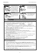
Safety Summary ENGLISH VERSION EO1-33034 6DIHW\ 6XPPDU\ Personal safety in handling or maintaining the equipment is extremely important. Warnings and Cautions necessary for safe handling are included in this manual. All warnings and cautions contained in this manual should be read and understood before handling or maintaining the equipment. Do not attempt to effect repairs or modifications to this equipment.
Safety Summary ENGLISH VERSION EO1-33034 'LVFRQQHFW WKH SOXJ &RQQHFW D JURXQGLQJ ZLUH If foreign objects (metal fragments, water, liquids) enter the machines, first turn off the power switches and disconnect the power cord plugs from the outlet, and then contact your authorised TOSHIBA TEC representative for assistance. Continued use of the machine in that condition may cause fire or electric shock. Ensure that the equipment is properly grounded. Extension cables should also be grounded.
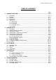
ENGLISH VERSION EO1-33034 TABLE OF CONTENTS Page 1. PRODUCT OVERVIEW ........................................................................................................E1-1 1.1 1.2 1.3 1.4 1.5 2. Introduction ..................................................................................................................E1-1 Features.......................................................................................................................E1-1 Unpacking .................................
ENGLISH VERSION EO1-33034 APPENDIX 1 SPECIFICATIONS.................................................................................................EA1-1 A1.1 Printer ..........................................................................................................................EA1-1 A1.2 Options ........................................................................................................................EA1-2 A1.3 Media ..................................................................
1. PRODUCT OVERVIEW ENGLISH VERSION EO1-33034 1.1 Introduction 1. PRODUCT OVERVIEW 1.1 Introduction Thank you for choosing the TEC B-SX4T series thermal printer. This Owner’s Manual contains from general set-up through how to confirm the printer operation using a test print, and should be read carefully to help gain maximum performance and life from your printer. For most queries please refer to this manual and keep it safe for future reference.
1. PRODUCT OVERVIEW ENGLISH VERSION EO1-33034 1.4 Accessories 1.4 Accessories When unpacking the printer, please make sure all the following accessories are supplied with the printer. US Power Cord (1 pc.) (P/No. FBCB0030203) QQ model only EU Power Cord (1 pc.) (P/No.EKA-0030001) QP model only CD-ROM (1 pc.) QQ (P/No.: 7FM00332100) QP (P/No.: 7FM00256100) Fan Filter (1 pc.) (P/No.
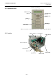
1. PRODUCT OVERVIEW ENGLISH VERSION EO1-33034 1.5 Appearance 1.5 Appearance 291291 (11.5) 460460 (18.1) 308 1.5.1 Dimensions The names of the parts or units introduced in this section are used in the following chapters. 308 (12.1) Dimensions in mm (inches) 1.5.2 Front View LCD Message Display Top Cover Operation Panel Supply Window Media Outlet 1.5.
1. PRODUCT OVERVIEW ENGLISH VERSION EO1-33034 1.5 Appearance LCD Message Display 1.5.4 Operation Panel POWER LED (Green) ON LINE LED (Green) ERROR LED (Red) [FEED] key [PAUSE] key [RESTART] key Please see Section 3.1 for further information about the Operation Panel. 1.5.
2. PRINTER SETUP ENGLISH VERSION EO1-33034 2.1 Precautions 2. PRINTER SETUP This section outlines the procedures to setup your printer prior to its operation. The section includes precautions, connecting cables, assembling accessories, loading media and ribbon, inserting the optional memory card, and performing a test print. 2.1 Precautions To insure the best operating environment, and to assure the safety of the operator and the equipment, please observe the following precautions.
2. PRINTER SETUP ENGLISH VERSION EO1-33034 2.2 Procedure before Operation 2.2 Procedure before Operation NOTE: To communicate with the host computer, one of the following cables is required. (1) RS-232C cable: 25 pins (2) Centronics cable: 36 pins (3) USB: B plug (Option) (4) LAN: 10 Base-T or 100 Base-TX (Option) This section describes the outline of the printer setup. 1. Unpack the accessories and printer from the box. 2.
2. PRINTER SETUP ENGLISH VERSION EO1-33034 2.4 Connecting the Cables to Your Printer 2.4 Connecting the Cables to Your Printer The following paragraphs outline how to connect the cables from the printer to your host computer, and will also show how to make cable connections to other devices. Depending on the application software you use to print labels, there are 4 possibilities for connecting the printer to your host computer.
2. PRINTER SETUP ENGLISH VERSION EO1-33034 2.5 Connecting the Power Cord 2.5 Connecting the Power Cord CAUTION! 1. Make sure that the printer Power Switch is turned to the OFF position ( ) before connecting the Power Cord to prevent possible electric shock or damage to the printer. 2. Use only the Power Cord supplied with the printer. Use of any other cord may cause electric shock or fire. 3. Connect the Power Cord to a supply outlet with a properly grounded (earthed) connection. { 1.
2. PRINTER SETUP ENGLISH VERSION EO1-33034 2.6 Turning the Printer ON/OFF 2.6 Turning the Printer ON/OFF When the printer is connected to your host computer it is good practice to turn the printer ON before turning on your host computer and turn OFF your host computer before turning off the printer. 2.6.1 Turning ON the Printer 1. To turn ON the printer power, press the Power Switch as shown in the CAUTION! diagram below. Note that ( | ) is the power ON side of the switch.
2. PRINTER SETUP ENGLISH VERSION EO1-33034 2.7 Loading the Media 2.7 Loading the Media WARNING! 1. Do not touch any moving parts. To reduce the risk of fingers, jewellery, clothing, etc., being drawn into the moving parts, be sure to load the media once the printer has stopped moving completely. 2. The Print Head becomes hot immediately after printing. Allow it to cool before loading the media. 3. To avoid injury, be careful not to trap your fingers while opening or closing the cover.
2. PRINTER SETUP ENGLISH VERSION EO1-33034 2.7 Loading the Media 2.7 Loading the Media (Cont.) NOTE: Do not over-tighten the Locking Ring of the Supply Holder. 5. 6. 7. Put the media on the Supply Shaft. Pass the media around the Damper, then pull the media towards the front of the printer. Align the projection of the Supply Holder with the groove of the Supply Shaft, and push the Supply Holder against the media until the media is held firmly in place. This will center the media automatically.
2. PRINTER SETUP ENGLISH VERSION EO1-33034 2.7 Loading the Media 2.7 Loading the Media (Cont.) 10. Lower the Print Head Block until it stops. 11. After loading the media, it may be necessary to set the Media Sensors used to detect the print start position for label or tag printing. Setting the Feed Gap Sensor position NOTE: Be sure to set the black mark sensor to detect the centre of the black mark, otherwise a paper jam or no paper error may occur.
2. PRINTER SETUP ENGLISH VERSION EO1-33034 2.7 Loading the Media 2.7 Loading the Media (Cont.) 12. There are four issue modes available on this printer. How to set the media for each mode is provided below. Batch mode In the batch mode, the media is continuously printed and fed until the number of labels/tags specified in the issue command have been printed. 1. 2. 3. 4. NOTES: Be sure to set the Selection Switch to STANDARD/ PEEL OFF position.
2. PRINTER SETUP ENGLISH VERSION EO1-33034 2.7 Loading the Media 2.7 Loading the Media (Cont.) NOTE: Be sure to set the Selection Switch to REWINDER position. ADJUSTMENT: If the media skews when using the Built-in Rewinder, turn the Adjustment Knob of the Rewinder Guide Plate to correct the media feed. Clockwise turn moves the Rewinder Guide Plate forward and counter-clockwise moves it backward.
2. PRINTER SETUP ENGLISH VERSION EO1-33034 2.8 Loading the Ribbon 2.8 Loading the Ribbon WARNING! 1. Do not touch any moving parts. To reduce the risk of fingers, jewellery, clothing, etc., being drawn into the moving parts, be sure to load the ribbon once the printer has stopped moving completely. 2. The print head becomes hot immediately after printing. Allow it to cool before loading the ribbon. 3. To avoid injury, be careful not to trap your fingers while opening or closing the cover.
2. PRINTER SETUP ENGLISH VERSION EO1-33034 2.8 Loading the Ribbon 2.8 Loading the Ribbon (Cont.) 3. Slide the Ribbon Stoppers along the Ribbon Shafts to a position where the ribbon is centred when fitted. 4. Lower the Print Head Block and set the Ribbon Shaft Holder Plate aligning its holes with the Ribbon Shafts. 5. Take up any slack in the ribbon. Wind the leading tape onto the ribbon take-up roll until the ink ribbon can be seen from the front of the printer. Ribbon Shaft Holder Plate 6.
2. PRINTER SETUP ENGLISH VERSION EO1-33034 2.9 Inserting the Optional PCMCIA Cards 2.9 Inserting the Optional When the optional PCMCIA Interface Board is installed into the printer, there will be two PCMCIA slots available as shown in the figure below. PCMCIA Cards 1. 2. 3. 4. 5. CAUTION! To protect PC cards, discharge static electricity from your body by touching the metal cabinet of the printer before touching the card.
2. PRINTER SETUP ENGLISH VERSION EO1-33034 2.10 Test Print 2.10 Test Print A print test should be performed to check that the printer is operating correctly. The following paragraphs guide you through the diagnostic procedure for test label printing. Please follow the step-by-step procedures exactly for best results. 1. Use label stock for the test print. For best results, use labels that are 76 mm or longer in length. 2.
2. PRINTER SETUP ENGLISH VERSION EO1-33034 2.10 Test Print 2.10 Test Print (Cont.) 9. Press the [PAUSE] key and the issue mode setting display will appear. Select the issue mode with the [FEED] or [RESTART] key. !7(67 35,17 7<3( >6@12 &87 10. Press the [PAUSE] key and the media size setting display will appear. Select the media size with the [FEED] or [RESTART] key. !7(67 35,17 /$%(/ /(1 PP NOTE: When PAPER FEED is selected, the printer feeds the media to the correct print start position.
2. PRINTER SETUP ENGLISH VERSION EO1-33034 2.10 Test Print 2.10 Test Print (Cont.) 19. When you have finished performing the test print operation, turn the printer’s power OFF then back to ON and check that the LCD Message Display shows ON LINE and that the ON LINE and POWER LED lights are illuminated.
2. PRINTER SETUP ENGLISH VERSION EO1-33034 2.10 Test Print 2.10 Test Print (Cont.
3. ON LINE MODE ENGLISH VERSION EO1-33034 3.1 Operation Panel 3. ON LINE MODE This chapter describes usage of the keys on the Operation Panel in On Line mode. When the printer is in On Line mode and connected to a host computer, the normal operation of printing images on labels or tags can be accomplished. 3.1 Operation Panel • The figure below illustrates the operation panel and key functions.
3. ON LINE MODE ENGLISH VERSION EO1-33034 3.2 Operation 3.2 Operation When the printer is turned on, the “ON LINE” message appears on the LCD Message Display. It is shown during standby or normal printing. 1. The printer is turned on, standing by, or printing. 21 /,1( % 6; 7 9 $ 2. If any error occurs during printing, an error message appears. The printer stops printing automatically. (The number on the right side shows the remaining number of media to be printed.
3. ON LINE MODE ENGLISH VERSION EO1-33034 3.4 Dump Mode 3.4 Dump Mode In Dump mode, any characters sent from the host computer will be printed. Received characters are expressed in hexadecimal values. This allows the user to verify programming commands and debug the program. For details, please refer to your nearest TOSHIBA TEC service representative.
4. MAINTENANCE ENGLISH VERSION EO1-33034 4.1 Cleaning 4. MAINTENANCE 1. 2. 3. 4. WARNING! Be sure to disconnect the power cord before performing maintenance. Failure to do this may cause an electric shock. To avoid injury, be careful not to pinch your fingers while opening or closing the cover and print head block. The print head becomes hot immediately after printing. Allow it to cool before performing any maintenance. Do not pour water directly onto the printer.
4. MAINTENANCE ENGLISH VERSION EO1-33034 4.1 Cleaning 4.1.1 Print Head/Platen/ Sensors (Cont.) NOTE: Please purchase the Print Head Cleaner (P/No. 24089500013) from your authorised TOSHIBA TEC service representative. 6. Clean the Print Head Element with a Print Head Cleaner or a cotton swab or soft cloth slightly moistened with alcohol. Pinch Roller Print Head Print Head Element Platen Feed Roller Black Mark Sensor/ Feed Gap Sensor 7.
4. MAINTENANCE ENGLISH VERSION EO1-33034 4.2 Care/Handling of the Media and Ribbon 4.1.3 Optional Cutter Module The swing cutter and rotary cutter are available as an option. They are WARNING! 1. Be sure to turn the power off before cleaning the Cutter Module. 2. As the cutter blade is sharp, care should be taken not to injure yourself when cleaning. both cleaned in the same way. When removing the Cutter Cover of the rotary cutter unit, remove the screws from the bottom of the cover. 1. 2. 3. 4. 5.
5. TROUBLESHOOTING ENGLISH VERSION EO1-33034 5.1 Error Messages 5. TROUBLESHOOTING This chapter lists the error messages, possible problems, and their solutions. WARNING! If a problem cannot be solved by taking the actions described in this chapter, do not attempt to repair the printer. Turn off and unplug the printer, then contact an authorised TOSHIBA TEC service representative for assistance. 5.
5. TROUBLESHOOTING ENGLISH VERSION EO1-33034 5.2 Possible Problems 5.1 Error Messages (Cont.) Error Messages NO PAPER **** Problems/Cause 1. The media has run out. 2. The media is not loaded properly. RIBBON ERROR **** 3. The media is slack. The ribbon is not fed properly. NO RIBBON **** The ribbon has run out. REWIND FULL **** The Built-In Rewinder Unit is full. EXCESS HEAD TEMP The Print Head has overheated. HEAD ERROR There is a problem with the Print Head.
5. TROUBLESHOOTING ENGLISH VERSION EO1-33034 5.3 Removing Jammed Media 5.3 Removing Jammed Media This section describes in detail how to remove jammed media from the printer. CAUTION! Do not use any tool that may damage the Print Head. 1. Turn off and unplug the printer. 2. Open the Top Cover. 3. Turn the Head Lever to Free position, then open the Ribbon Shaft Holder Plate. 4. Open the Print Head Block. 5. Remove the ribbon and media.
5. TROUBLESHOOTING ENGLISH VERSION EO1-33034 5.4 Threshold Setting 5.4 Threshold Setting 1. 2. 3. 4. 5. 6. NOTES: If the [PAUSE] key is released within 3 seconds while in the pause state, the paper will not feed. Failure to feed more than 1.5 labels may result in an incorrect threshold setting. While the Print Head Block is raised, the [PAUSE] key does not work. A paper end error cannot be detected during paper feed.
APPENDIX 1 SPECIFICATIONS ENGLISH VERSION EO1-33034 A1.1 Printer APPENDIX 1 SPECIFICATIONS Appendix 1 describes the printer specifications and supplies for use on the B-SX4T printer. A1.1 Printer The following is the printer specifications. Model Item Supply voltage Power consumption During a print job During standby Operating temperature range Relative humidity Resolution Printing method Printing speed Available media width (including backing paper) Effective print width (max.
APPENDIX 1 SPECIFICATIONS ENGLISH VERSION EO1-33034 A1.2 Options A1.2 Options Option Name Swing cutter module Rotary cutter module Strip module Type B-4205-QM B-8204-QM B-9904-H-QM Ribbon saving module Expansion I/O interface board PCMCIA interface board B-9904-R-QM Built-in LAN interface board USB interface board B-9700-LAN-QM B-7704-IO-QM B-9700-PCM-QM B-9700-USB-QM Description A stop and cut swing cutter.
APPENDIX 1 SPECIFICATIONS ENGLISH VERSION EO1-33034 A1.3 Media A1.3.1 Media Type (Cont.) Label dispensing mode Item c Media pitch d Label length e Width including backing paper (See NOTE 5.) f Label width (See NOTE 5.) g Gap length h Black mark length (Tag paper) i Effective print width Label j Effective print length Tag k Print speed up/slow down area Label Tag [Unit: mm] Batch mode Strip mode 10.0 – 1500.0 25.4 – 1500.0 10.0 – 1500.0 ---8.0 – 1498.0 23.4 – 1498.0 30.0 – 112.0 50.0 – 112.0 27.
APPENDIX 1 SPECIFICATIONS ENGLISH VERSION EO1-33034 A1.3 Media A1.3.2 Detection Area of the Transmissive Sensor (Cont.) Centre of media Sensor position Print side Square holes (Round holes are not acceptable.) Min. 2.0 mm Min. 12 mm Media feed direction Sensor is movable within this range. NOTE: Round holes are not acceptable. A1.3.3 Detection Area of the Reflective Sensor The Reflective Sensor is movable from the centre to the left edge of media.
APPENDIX 1 SPECIFICATIONS ENGLISH VERSION EO1-33034 A1.4 Ribbon A1.3.4 Effective Print Area (Cont.) The figure below shows the effective print area on the media. Area to be detected. 1mm Start line Media height 10 – 1500 mm 1.5 mm from the left edge of media 1.5 mm from the right edge of media Guaranteed print area Media feed direction 1mm Area to be detected. Media width (backing paper width is not included.) NOTES: 1. Be sure not to print on the 1.
APPENDIX 2 MESSAGES AND LEDS ENGLISH VERSION EO1-33034 APPENDIX 2 MESSAGES AND LEDS APPENDIX 2 MESSAGES AND LEDS Appendix 2 describes the LCD messages displayed on the operation panel. Symbols in the message 1: : The LED is illuminated. ~: The LED is flashing. z: The LED is unlit. 2: ****: the number of unprinted media.
APPENDIX 2 MESSAGES AND LEDS ENGLISH VERSION EO1-33034 APPENDIX 2 MESSAGES AND LEDS NOTES: • If a command error is found in the command received, 16 bytes of the command error, starting from the command code, will be displayed. (However, [LF] and [NUL] will not be displayed.) Example 1 [ESC] T20 G30 [LF] [NUL] Command error The following message appears. 7 * % 6; 7 9 $ Example 2 [ESC] XR; 0200, 0300, 0450, 1200, 1, [LF] [NUL] Command error The following message appears.
APPENDIX 3 INTERFACE ENGLISH VERSION EO1-33034 APPENDIX 3 INTERFACE APPENDIX 3 INTERFACE Interface Cables To prevent radiation and reception of electrical noise, the interface cables must meet the following requirements: • Fully shielded and fitted with metal or metallised connector housings. • Keep as short as possible. • Should not be bundled tightly with power cords. • Should not be tied to power line conduits.
APPENDIX 4 PRINT SAMPLES ENGLISH VERSION EO1-33034 APPENDIX 4 PRINT SAMPLES APPENDIX 4 PRINT SAMPLES Font EA4-1
APPENDIX 4 PRINT SAMPLES ENGLISH VERSION EO1-33034 APPENDIX 4 PRINT SAMPLES APPENDIX 4 PRINT SAMPLES (Cont.
APPENDIX 4 PRINT SAMPLES ENGLISH VERSION EO1-33034 APPENDIX 4 PRINT SAMPLES APPENDIX 4 PRINT SAMPLES (Cont.
GLOSSARIES ENGLISH VERSION EO1-33034 GLOSSARIES GLOSSARIES Bar code Expansion I/O interface A code which represents alphanumeric characters by using a series of black and white stripes in different widths. Bar codes are used in various industrial fields: Manufacturing, Hospitals, Libraries, Retail, Transportation, Warehousing, etc. Reading bar codes is a fast and accurate means of capturing data while keyboard entry tends to be slow and inaccurate.
GLOSSARIES ENGLISH VERSION EO1-33034 GLOSSARIES Pre-printed media Thermal direct printing A type of media on which characters, logos, and other designs have been already printed. A printing method using no ribbon, but thermal media which reacts to heat. The thermal print head heats the thermal media directly, causing print image to be printed on the media.
INDEX ENGLISH VERSION EO1-33034 INDEX INDEX A J Auto ribbon saving 2-12 Jammed media 5-3 B L Backing paper A1-3 Bar code A1-1 Batch mode 2-9 Black mark 2-8, A1-2, A1-4 Black mark length A1-3 Black mark sensor 2-8, 4-2 Built-in rewinder 2-10 Label 2-6, A1-2, A1-3 LCD message display 1-3, 1-4, 3-1 M Media 2-6, 4-3, A1-2 Media length A1-3 Media pitch A1-3 Media sensor 2-8 C Centronics 1-3, 2-3 Cut mode 2-10 Cutter module 2-10, 4-3, A1-2 O D P Dimensions 1-3 Parallel interface 1-3 Parallel port
INDEX ENGLISH VERSION EO1-33034 INDEX S Serial interface 1-3 Strip mode 2-9 Strip module 2-9, A1-2 Supply voltage A1-1 T Tag A1-2 Test print 2-14 Thermal direct 2-14, A1-1 Thermal transfer 2-14, A1-1 Threshold setting 5-4 Transmissive sensor 2-14, A1-3 Two-dimensional code A1-1 U USB interface 1-3, 2-3, A1-2 W Weight A1-1
M EO1-33034B