+00EH99864801_00Ta.
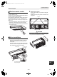
+00EH99864801_00Ta.book Page 1 Tuesday, November 24, 2009 5:40 PM Installation Manual Under Ceiling Type Please read this Installation manual carefully before installing the Air Conditioner. • This Manual describes the installation method of the indoor unit. • For installation of the outdoor unit, follow the Installation Manual attached to the outdoor unit. ADOPTION OF NEW REFRIGERANT This Air Conditioner uses R410A an environmentally friendly refrigerant. Contents 1 ACCESSORY PARTS. . . . . . . . . .
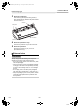
+00EH99864801_00Ta.book Page 2 Tuesday, November 24, 2009 5:40 PM Installation Manual Under Ceiling Type 1 ACCESSORY PARTS Accessory parts Part name Q’ty Shape Usage Owner’s Manual 1 – – Installation Manual 1 This manual Installation pattern 1 – Thermal insulation pipe 2 Washer 4 Hose band 2 For connecting drain pipe Drain hose 1 For connecting drain pipe Bushing Ø2.2” (Ø56) 1 For protection of edge at hole for remote control wires Bushing Ø1.
+00EH99864801_00Ta.book Page 3 Tuesday, November 24, 2009 5:40 PM Installation Manual Under Ceiling Type 2 PRECAUTIONS FOR SAFETY Installing, starting up, and servicing air--conditioning equipment can be hazardous due to system pressures, electrical components, and equipment location (roofs, elevated structures, etc.). Only trained, qualified installers and service mechanics should install, start--up, and service this equipment.
+00EH99864801_00Ta.book Page 4 Tuesday, November 24, 2009 5:40 PM Installation Manual Under Ceiling Type • Conform to the regulations of the local electric company when wiring the power supply. Inappropriate grounding may cause electric shock. • For the refrigerant recovery work (collection of refrigerant from the pipe to the compressor), stop the compressor before disconnecting the refrigerant pipe.
+00EH99864801_00Ta.book Page 5 Tuesday, November 24, 2009 5:40 PM Installation Manual Under Ceiling Type 3 SELECTION OF INSTALLATION PLACE Installation space WARNING • Install the air conditioner at enough strong place to withstand the weight of the unit. If the strength is not enough, the unit may fall down resulting in injury. • Install the air conditioner at a height 8’ (2.4 m) or more from the floor.
+00EH99864801_00Ta.book Page 6 Tuesday, November 24, 2009 5:40 PM Installation Manual Under Ceiling Type 2 Wireless remote control Removing wire guard Remove the screws (2 pcs.) which are fixing the wire guard. Remove the clamp fixing screws and remove the wire guard. Decide the position which remote control is operated and the installation place. And then refer to the Installation Manual of the wireless remote controller kit sold separately.
+00EH99864801_00Ta.book Page 7 Tuesday, November 24, 2009 5:40 PM Installation Manual Under Ceiling Type 3 Removal of side panel After removing the side panel fixing screws (1 each at right and left), slide the side panel forward and then remove it. Protector Side panel Level louver Slide forward. 4 Removal of protective vinyl Peel out the protective vinyl on the level louver. 5 Removal of protector Remove the protector (1 pcs.) of the fan.
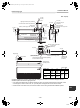
+00EH99864801_00Ta.book Page 8 Tuesday, November 24, 2009 5:40 PM Installation Manual Under Ceiling Type Unit: in (mm) 1.5” (39) 2.0” (52) 6.6” (167) 8.5” (216) Drain pipe connecting port B (Hanging position) 3.0” (75) 3.8” (97) 8.5” (216) (Gas pipe) 7.9” (200) (Liquid pipe) Refrigerant pipe (Gas side ØD) Drain port VP20 (Inner dia. Ø1.0” (26), hose attached) 26.8” (680) 5.1” (130) 2.1” (53) Refrigerant pipe (Liquid side ØC) Left drain size 2.0” (50) 4.3” (110) 3.0” (76) 4.
+00EH99864801_00Ta.book Page 9 Tuesday, November 24, 2009 5:40 PM Installation Manual Under Ceiling Type Pipe knockout hole Using attached installation pattern • Piping from rear side * Cut off the groove section with a plastic cutter, etc. Ceiling surface Wall face Rear cover Installation pattern 100 Using the pattern, positioning of the hanging bolt and pipe hole can be performed.
+00EH99864801_00Ta.book Page 10 Tuesday, November 24, 2009 5:40 PM Installation Manual Under Ceiling Type Installation of indoor unit (2) Hang the unit to the hanging bolt as shown the figure below. • Preparation before holding down main unit * Confirm the presence of the ceiling material beforehand because the fixing method of hanging metal when the ceiling material is set differs from that when the ceiling material is not set.
+00EH99864801_00Ta.book Page 11 Tuesday, November 24, 2009 5:40 PM Installation Manual Under Ceiling Type 4 REFRIGERANT PIPING AND EVACUATING Refrigerant Piping • The connecting sections of the refrigerant pipes are provided at the positions in the figure below. Upper side Rear side * When using the drain pump kit sold separately, the pipe can be drawn out only from the upper side. Permissible Piping Length and Height Difference They vary according to the outdoor unit.
+00EH99864801_00Ta.book Page 12 Tuesday, November 24, 2009 5:40 PM Installation Manual Under Ceiling Type Evacuation Tightening connection CAUTION Using a vacuum pump, perform vacuuming from the charge port of valve of the outdoor unit. For details, follow to the Installation Manual attached to the outdoor unit. • Never use the refrigerant sealed in the outdoor unit for air purge. • Do not apply excessive torque. Otherwise, the nut may crack depending on the conditions.
+00EH99864801_00Ta.book Page 13 Tuesday, November 24, 2009 5:40 PM Installation Manual Under Ceiling Type Thermal insulation process Apply thermal insulation for the pipes separately at liquid side and gas side. For the thermal insulation to the pipes at gas side, be sure to use the material with heat-resisting temperature 248 °F (120 °C) or higher. Using the attached thermal insulation material, apply the thermal insulation to the pipe connecting section of the indoor unit securely without gap.
+00EH99864801_00Ta.book Page 14 Tuesday, November 24, 2009 5:40 PM Installation Manual Under Ceiling Type 5 DRAIN PIPING WORK • Set the collective piping as shown in the below figure. CAUTION As long as possible (3.9” (100 mm)) • Following the Installation Manual, perform the drain piping work so that water is properly drained, and apply a heat insulation so as not to cause a dew dropping. Inappropriate piping work may result in water leakage in the room and wet of furniture.
+00EH99864801_00Ta.book Page 15 Tuesday, November 24, 2009 5:40 PM Installation Manual Under Ceiling Type Connection of drain hose Connection of drain pipe • Insert the attached drain hose into the drain pipe connecting port on the drain pan up to the end. • Fit the attached hose band to the end of the pipe connecting port, and then tighten it securely. • Connect the hard vinyl chloride pipe (procured locally) to the mounted drain hose which was attached.
+00EH99864801_00Ta.book Page 16 Tuesday, November 24, 2009 5:40 PM Installation Manual Under Ceiling Type 6 ELECTRICAL CONNECTION REQUIREMENT WARNING 1. Using the specified wires, ensure to connect the wires, and fix wires securely so that the external tension to the wires do not affect the connecting part of the terminals. Incomplete connection or fixation may cause a fire, etc. 2. Be sure to connect ground wire. (grounding work) Incomplete grounding cause an electric shock.
+00EH99864801_00Ta.book Page 17 Tuesday, November 24, 2009 5:40 PM Installation Manual Under Ceiling Type CAUTION Use the same size wire for the field power supply wire and system interconnection wires when the outdoor unit is RAV-SP180AT2. NOTE • Use copper supply wires. • Use UL wires rated 600 V for the system interconnection wires. • Use UL wires rated 300 V for the remote control wires.
+00EH99864801_00Ta.book Page 18 Tuesday, November 24, 2009 5:40 PM Installation Manual Under Ceiling Type Wire connection REQUIREMENT • Be sure to connect the wires matching the terminal numbers. Incorrect connection causes a trouble. • The low-voltage circuit is provided for the remote control. (Do not connect the high-voltage circuit) • • • • Loosen the cover mounting screws (2 positions) of the electric parts box, and then remove the cover.
+00EH99864801_00Ta.book Page 19 Tuesday, November 24, 2009 5:40 PM Installation Manual Under Ceiling Type CAUTION Fix the system interconnection wires and the remote control wires separately with the cord clamps as shown below.
+00EH99864801_00Ta.book Page 20 Tuesday, November 24, 2009 5:40 PM Installation Manual Under Ceiling Type System interconnection Wires and Ground Wire Remote Control Wiring 1. Strip wire ends. System interconnection wire : 0.4” (10 mm). Ground wire : 0.8” (20 mm) 2. Match wire colours with terminal numbers on indoor and outdoor units’ terminal blocks and firmly screw wires to the corresponding terminals. 3. Secure the ground wire with the ground screw. 4. Fix the wire with cord clamp.
+00EH99864801_00Ta.book Page 21 Tuesday, November 24, 2009 5:40 PM Installation Manual Under Ceiling Type 7 APPLICABLE CONTROLS REQUIREMENT • When you use this air conditioner for the first time, it takes approx. 5 minutes until the remote control becomes available after power-on. This is normal. It takes approx. 5 minutes until the remote control becomes available.
+00EH99864801_00Ta.book Page 22 Tuesday, November 24, 2009 5:40 PM Installation Manual Under Ceiling Type Procedure 5 Push button. In this time, if the display changes from flashing to lighting, the setup completes. • To change the setup of an indoor unit other than the selected one, start operation from Procedure 2. • To change the setup of another setup in the selected indoor unit, start operation from Procedure 3. Pushing button clears the set up contents which have been already set.
+00EH99864801_00Ta.book Page 23 Tuesday, November 24, 2009 5:40 PM Installation Manual Under Ceiling Type Filter sign setting Group control According to the installation condition, the lighting time of the filter sign (Notification of filter cleaning) can be changed. Follow to the basic operation procedure (1 → 2 → 3 → 4 → 5 → 6). • For the CODE No. in Procedure 3, specify [01]. • For the [SET DATA] in Procedure 4, select the setup data of filter sign lighting time from the following table.
+00EH99864801_00Ta.book Page 24 Tuesday, November 24, 2009 5:40 PM Installation Manual Under Ceiling Type Indoor UNIT No. before setup change is displayed. 7 3 -1, 4 -1, 5 -1, 3 -2, 4 -2, 5 -2 7 1 2,6 3 -3, 4 -3, 5 -3, Procedure 4 Procedure 1 Push simultaneously + + buttons for 4 seconds or more. After a while, the display part flashes as shown below. Check the displayed CODE No. is [10]. • When the CODE No.
+00EH99864801_00Ta.book Page 25 Tuesday, November 24, 2009 5:40 PM Installation Manual Under Ceiling Type Procedure 6 If there is other indoor unit to be changed, repeat procedure 2 to 5 to change the setup. When the above setup has finished, push to select the indoor UNIT No. before change of setup, specify CODE No. [12], [13], [14] in order with temp. setup / buttons, and then check the changed contents.
+00EH99864801_00Ta.book Page 26 Tuesday, November 24, 2009 5:40 PM Installation Manual Under Ceiling Type Remote control switch monitoring function Outdoor unit data CODE No.
+00EH99864801_00Ta.book Page 27 Tuesday, November 24, 2009 5:40 PM Installation Manual Under Ceiling Type 8 TEST RUN Procedure 2 Before test run Push • Before turning on the circuit breaker, carry out the following procedure. 1) Using 500V-megger, check 1MΩ or more exists between the terminal block L1 to L2 and the ground. If 1MΩ or less is detected, do not run the unit. Do not apply to the remote control circuit. 2) Check the valve of the outdoor unit being opened fully.
+00EH99864801_00Ta.book Page 28 Tuesday, November 24, 2009 5:40 PM Installation Manual Under Ceiling Type ▼ Heating test run: Wireless remote control Procedure 1 Turn on the circuit breaker of the air conditioner. The operation is not accepted for 5 minutes when circuit breaker is turned on at first time after installation, and 1 minute when circuit breaker is turned on at the next time and after. After the specified time has passed, perform a test operation.
+00EH99864801_00Ta.book Page 29 Tuesday, November 24, 2009 5:40 PM Installation Manual Under Ceiling Type 9 TROUBLESHOOTING Procedure 2 Confirmation and check When a trouble occurred in the air conditioner, the check code and the indoor UNIT No. appear on the display part of the remote control. The check code is only displayed during the operation. If the display disappears, operate the air conditioner according to the following “Confirmation of error history” for confirmation.
+00EH99864801_00Ta.
+00EH99864801_00Ta.book Page 31 Tuesday, November 24, 2009 5:40 PM Installation Manual Under Ceiling Type F31 (L29) SIM Outdoor unit P.C. board Outdoor Outdoor P.C. board ---- In the case of EEPROM error.
+00EH99864801_00Ta.book Page 32 Tuesday, November 24, 2009 5:40 PM Installation Manual Under Ceiling Type P22 ALT Outdoor unit fan error Outdoor Outdoor unit fan motor, outdoor unit P.C. board --- An error (overcurrent, locking, etc.) was detected in the outdoor unit fan drive circuit. Entire stop P26 ALT Outdoor unit inverter Idc activated Outdoor IGBT, outdoor unit P.C.
+00EH99864801_00Ta.