SERVICE HANDBOOK MULTIFUNCTIONAL DIGITAL COLOR SYSTEMS e-STUDIO281c/351c/451c File No.
© 2005 TOSHIBA TEC CORPORATION All rights reserved
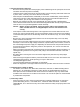
GENERAL PRECAUTIONS REGARDING THE SERVICE FOR e-STUDIO281c/351c/451c The installation and service should be done by a qualified service technician. 1) Transportation/Installation - When transporting/installing the equipment, employ four persons and be sure to hold the positions as shown in the figure. The equipment is quite heavy and weighs approximately 113 kg (249 lb), therefore pay full attention when handling it. - Be sure not to hold the movable parts or units (e.g.
2) General Precautions at Service - Be sure to turn the power OFF and unplug the power cable during service (except for the service should be done with the power turned ON). - Unplug the power cable and clean the area around the prongs of the plug and socket outlet once a year or more. A fire may occur when dust lies on this area. - When the parts are disassembled, reassembly is the reverse of disassembly unless otherwise noted in this manual or other related documents.
) Disposal of the Equipment, Supplies, Packing Materials, Used Batteries and IC-RAMs - Regarding the recovery and disposal of the equipment, supplies, packing materials, used batteries and IC-RAMs including lithium batteries, follow the relevant local regulations or rules. Caution: Dispose of used batteries and IC-RAMs including lithium batteries according to this manual. Attention: Se débarrasser de batteries et IC-RAMs usés y compris les batteries en lithium selon ce manuel.
CONTENTS 1. SPECIFICATIONS/ACCESSORIES/OPTIONS/SUPPLIES ......................................... 1-1 1.1 1.2 1.3 1.4 1.5 Specifications....................................................................................................................... 1-1 Accessories ......................................................................................................................... 1-7 Options .........................................................................................................
3.7 3.8 3.9 3.10 3.11 3.12 3.13 3.14 3.6.3 Gamma balance adjustment (Black Mode) ............................................................ 3-38 3.6.4 Color balance adjustment (Color Mode)................................................................. 3-39 3.6.5 Adjustment of smudged/faint text ........................................................................... 3-39 3.6.6 Upper limit value at Toner Saving Mode ................................................................ 3-40 3.6.
4. PREVENTIVE MAINTENANCE (PM)............................................................................ 4-1 4.1 PM Support Mode................................................................................................................ 4-1 4.1.1 General description .................................................................................................. 4-1 4.1.2 Operational flow and operational screen .................................................................. 4-1 4.1.
6.1.1 PWA-DWNLD-350-JIG2 (48 MB) ............................................................................. 6-4 6.1.2 Writing the data to the download jig (PWA-DWNLD-350-JIG) ............................... 6-13 6.1.3 K-PWA-DLM-320.................................................................................................... 6-15 6.2 Firmware Updating with USB Storage Device ................................................................... 6-26 6.2.1 Appendix ......................................
1. 2. 3. SPECIFICATIONS/ACCESSORIES/OPTIONS/ SUPPLIES ERROR CODE AND SELF-DIAGNOSTIC MODE 1 2 ADJUSTMENT 3 4. PREVENTIVE MAINTENANCE (PM) 4 5. TROUBLESHOOTING 5 6. FIRMWARE UPDATING 6 7. POWER SUPPLY UNIT 7 8. REMOTE SERVICE 8 9. DATA CLONING with USB STORAGE DEVICE 9 10.
1. SPECIFICATIONS/ACCESSORIES/OPTIONS/SUPPLIES 1.1 1 Specifications yCopy process .......................... Indirect electrophotographic process (dry) yType......................................... Desktop type (Console type: when optional Paper Feed Pedestal (PFP) or optional Large Capacity Feeder (LCF) is installed.) yOriginal table ........................... Fixed type (the left rear corner used as guide to place originals) yAccepted originals ...................
• • • * Original: A4 or LT (single-sided) Mode: APS and Automatic density not selected, Plain paper mode Number of copies: Black mode: 28 sheets or more (e-STUDIO281c), 35 sheets or more (e-STUDIO351c), 45 sheets or more (e-STUDIO451c) Color mode: 11 sheets or more • Reproduction ratio: 100% The values in ( ) can be realized in the color mode. Thick paper / OHP e-STUDIO281c Thick1 (81 g/m2 to 105 g/m2, 21 lb. Bond to 28 lb.
e-STUDIO351c Thick1 (81 g/m2 to 105 g/m2, 21 lb. Bond to 28 lb. Bond) Paper supply Paper size A4, LT B5, A5-R, ST-R A4-R, B5-R, LT-R B4, LG A3, LD Drawer 30 (11) 23 (5) 19 (5) 16 (5) Bypass feed Size not Size specified specified 30 (11) 16 (5) 23 (5) 19 (5) 16 (5) 16 (5) 16 (5) 16 (5) PFP 30 (11) 23 (5) 19 (5) 16 (5) LCF (A4/LT only) 30 (11) - Thick2 (106 g/m2 to 163 g/m2, 29 lb. Bond to 90 lb.
e-STUDIO451c Thick1 (81 g/m2 to 105 g/m2, 21 lb. Bond to 28 lb. Bond) Paper supply Paper size A4, LT B5, A5-R, ST-R A4-R, B5-R, LT-R B4, LG A3, LD Drawer 30 (11) 23 (5) 19 (5) 16 (5) Bypass feed Size not Size specified specified 30 (11) 16 (5) 23 (5) 19 (5) 16 (5) 16 (5) 16 (5) 16 (5) PFP 30 (11) 23 (5) 19 (5) 16 (5) LCF (A4/LT only) 30 (11) - Thick2 (106 g/m2 to 163 g/m2, 29 lb. Bond to 90 lb.
* System copy speed Copy mode Single-sided originals ↓ Single-sided copies 1 set 3 sets 5 sets e-STUDIO281c 31.26 (71.97) 74.07 (182.19) 116.64 (289.94) Single-sided originals ↓ Double-sided copies 1 set 3 sets 5 sets 1 set 3 sets 5 sets 1 set 3 sets 5 sets 32.61 (81.63) 74.69 (189.38) 117.45 (299.04) 64.24 (138.12) 150.73 (355.91) 234.59 (574.51) 58.85 (128.31) 143.68 (347.08) 228.58 (565.02) Double-sided originals ↓ Double-sided copies Double-sided originals ↓ Single-sided copies * Sec.
yEliminated portion.................... Leading edges: 3.0±2.0 mm, Side/trailing edges: 2.0±2.0 mm (black copy) Leading edges: 5.0±2.0 mm, Side/trailing edges: 2.0±2.0 mm (color copy) Leading / trailing edges: 5.0±2.0 mm, Side edges: 5.0±2.0 mm (black / color print) yPaper feeding .......................... Standard drawers: 2 drawers (stack height 60.5 mm, equivalent to 550 sheets; 64 to 80 g/ m2 (17 to 22 lb. Bond)) PFP: Option (One drawer or two: stack height 60.
1.2 * Accessories Unpacking/Setup instruction Operator’s manual Operator's manual pocket Power cable Warranty sheet Setup report PM sticker Drum (installed inside of the equipment) Control panel stopper Color developer holder Rubber plug Blind seal (small / large) CD-ROM Developer material (Y, M, C, K) Screw M4 x 8 Guide Approval sheet Toner cartridge (Y, M, C, K) 1 set 4 pcs. (except for MJD and ASU) 1 pc. 1 pc. 1 pc. (for NAD) 1 set (for NAD, MJD and CND) 1 pc. (for MJD) 1 pc. 1 pc. 6 pc. 4 pcs.
1.
1.
e-STUDIO281c/351c/451c SPECIFICATIONS/ACCESSORIES/OPTIONS/SUPPLIES 1 - 10 05/11 Saddle stitch Finisher MJ-1024 Finisher MJ-1023 Staple Cartridge STAPLE-2000 Staple Cartridge STAPLE-1600 Hanging Finisher MJ-1022 Staple Cartridge STAPLE-600 Hole Punch Unit MJ-6004 N/E/F/S Data overwrite kit GP-1060 Expansion memory GC-1230 Parallel interface kit GF-1140 Antenna GN-3010 Expansion memory GC-1181 Scrambler board GP-1040 Bluetooth module GN-2010 PCI slot GO-1060 Damp Heater MF-3511U/E Work Tray
2. ERROR CODE AND SELF-DIAGNOSTIC MODE 2.1 Error Code List The following error codes is displayed at the upper right of the screen when the “CLEAR PAPER” or “CALL SERVICE” symbol is blinking. 2.1.1 Jam Error code E010 Classification Paper exit jam E020 Paper exit jam E030 Other paper jam E061 E062 E063 E064 E065 E090 June 2005 © TOSHIBA TEC Contents Jam not reaching the exit sensor : The paper which has passed through the fuser unit does not reach the exit sensor.
Error code E110 Classification Paper misfeeding E120 E130 E140 E150 E160 E190 E200 Paper transport jam Contents Troubleshooting ADU misfeeding (Paper not reaching the registration sensor): The paper which has passed through ADU does not reach the registration sensor during duplex printing. Bypass misfeeding (Paper not reaching the registration sensor): The paper fed from the bypass tray does not reach the registration sensor.
Error code E210 Classification Paper transport jam E220 E300 E310 E320 E330 E340 E350 E360 E400 Cover open jam E410 E420 Cover open jam E430 E440 E450 E480 E510 Paper transport jam (ADU section) E520 June 2005 © TOSHIBA TEC Contents Troubleshooting Lower drawer transport jam (Paper not reaching the registration sensor): The paper does not reach the registration sensor after it has passed the upper drawer feed sensor.
Error code Classification E550 Other paper jam E712 RADF jam E713 E714 E721 E722 E724 E725 E731 E860 E870 E910 Finisher jam (Bridge unit) E920 E930 E940 E9F0 Finisher jam (Punch unit) Contents Troubleshooting Paper remaining jam on the transport path: The paper is remaining on the transport path when printing is finished (caused by a multiple paper feeding).
Error code EA10 Classification Finisher jam (Finisher section) EA20 EA30 EA40 Finisher jam (Finisher section) EA50 EA60 EA70 EA80 EA90 Finisher jam (Saddle stitcher section) EAA0 EAB0 EAC0 EAD0 Other paper jam EAE0 Finisher jam June 2005 © TOSHIBA TEC Contents Troubleshooting Paper transport delay jam: The paper which has passed the bridge unit does not reach the inlet sensor. [MJ-1022/ 1023/1024] Paper transport stop jam: (1) The paper does not pass through the inlet sensor.
Error code EAF0 Classification Finisher jam (Finisher section) EB30 Finisher jam EB50 Paper transport jam EB60 Contents Stack return jam: It cannot load the paper which passed through the delivery roller on the intermediary process tray. [MJ-1022] Ready time time-out jam: The equipment judges that the paper transport to the finisher is disabled because of the communication error between the equipment and finisher at the start of printing.
2.1.2 Service call Error code C010 Classification Drive system related service call C020 C030 C040 Paper feeding system related service call C130 C140 C150 C160 C180 C1A0 C1B0 C260 Scanning system related service call C270 C280 C360 Copy process related service call June 2005 © TOSHIBA TEC Contents Main motor abnormality: The main motor is not rotating normally. Developer motor abnormality: The developer motor is not rotating normally.
Error code Classification C411 Fuser unit related service call C412 C443 C445 C446 C447 C449 C471 C472 C475 C480 C490 C4B0 C550 C570 C580 C900 C940 C950 C960 C970 C9E0 CA10 CA20 Contents Thermistor or heater abnormality at power-ON: Abnormality of the thermistor is detected when power is turned ON or the temperature of the fuser roller does not rise in a specified period of time after power is turned ON.
Error code CB20 Classification Finisher related service call CB30 CB40 CB50 CB60 CB80 CB90 CBA0 CBB0 CBC0 CBD0 CBE0 CBF0 CC00 CC10 June 2005 © TOSHIBA TEC Contents Troubleshooting Delivery motor abnormality: Delivery motor or delivery roller is not rotating normally. [MJ-1022] Tray 1/Tray 2 shift motor abnormality: Tray 1/Tray 2 shift motor is not rotating or delivery tray is not moving normally.
Error code CC20 Classification Finisher related service call CC30 CC40 CC50 CC60 CC80 CC90 CCA0 CCB0 CCD0 CCE0 CCF0 CE00 CE10 CE20 CE40 CE50 CE90 Image control related service call Contents Troubleshooting Communication error between finisher and saddle stitcher: Communication error between finisher controller PC board and saddle stitcher controller board [MJ-1023/1024] Stack processing motor abnormality: The stack processing motor is not rotating or the stack delivery belt is not moving
Error code CEA0 Classification Copy process related service call CEB0 CEC0 Copy process related service call CEE0 CEE1 CEF0 CF20 Toner density control related service call CF30 CF40 CF50 F070 F090 F091 F092 F100 Communication related service call Circuit related service call Other service call F101 F102 F103 F104 F105 F106 F107 F108 June 2005 © TOSHIBA TEC Contents Troubleshooting Revolver home position detection abnormality: It cannot detect that the revolver is at its home position.
Error code F110 F111 F120 F130 F200 F350 Classification Communication related service call Other service call Circuit related service call Contents Communication error between System-CPU and Scanner-CPU Scanner response abnormality Database abnormality: Database is not operating normally. Invalid MAC address Data overwrite kit (GP-1060) is taken off SLG board abnormality e-STUDIO281c/351c/451c ERROR CODE AND SELF-DIAGNOSTIC MODE 2 - 12 05/11 Troubleshooting Ch.5.1.12 Ch.5.1.12 Ch.5.1.20 Ch.5.1.20 Ch.
2.1.3 Error in Internet FAX / Scanning Function 1) Internet FAX related error Error code 1C10 Classification Troubleshooting System access abnormality Ch.5.1.21 [ 1 ] 1C11 Insufficient memory Ch.5.1.21 [ 1 ] 1C12 Message reception error Ch.5.1.21 [ 1 ] 1C13 Message transmission error Ch.5.1.21 [ 1 ] 1C14 Invalid parameter Ch.5.1.21 [ 1 ] 1C15 Exceeding file capacity Ch.5.1.21 [ 1 ] 1C20 System management module access abnormality Ch.5.1.
2) RFC related error Error code 2500 Message displayed in the TopAccess screen Syntax error, command unrecognized 2501 Syntax error in parameters or arguments 2503 Bad sequence of commands 2504 2550 Command parameter not implemented Mailbox unavailable 2551 User not local 2552 Insufficient system storage 2553 Mailbox name not allowed Contents HOST NAME error(RFC: 500) Destination mail address error (RFC: 500) Terminal mail address error (RFC: 500) HOST NAME error(RFC: 501) Destination mail add
3) Electronic Filing related error 2B10 Message displayed in the TopAccess screen There was no applicable job. Error code Contents Troubleshooting Ch.5.1.21 [ 3 ] 2B11 Job status failed. No applicable job error in job control module JOB status abnormality 2B20 Failed to access file. File library function error Ch.5.1.21 [ 3 ] 2B30 Insufficient disk space. Ch.5.1.21 [ 3 ] 2B31 Failed to access Electronic Filing. 2B32 Failed to print Electronic Filing document.
4) E-mail related error 2C10 Message displayed in the TopAccess screen Illegal Job status System access abnormality Ch.5.1.21 [ 4 ] 2C11 Not enough memory Insufficient memory Ch.5.1.21 [ 4 ] 2C12 Illegal Job status Message reception error Ch.5.1.21 [ 4 ] 2C13 Illegal Job status Message transmission error Ch.5.1.21 [ 4 ] 2C14 Invalid parameter specified Invalid parameter Ch.5.1.21 [ 4 ] 2C15 Ch.5.1.
5) File sharing related error 2D20 Message displayed in the TopAccess screen Illegal Job status Not enough memory Illegal Job status Illegal Job status Invalid parameter specified There are too many documents in the folder. Failed in creating new document.
6) E-mail reception related error Error code 3A10 3A11 3A12 3A20 3A21 3A22 3A30 3A40 3A50 3A51 3A52 3A60 3A61 3A62 3A70 3A80 3A81 3A82 3B10 3B11 3B12 Message displayed in the TopAccess screen MIME Error has been detected in the received mail. MIME Error has been detected in the received mail. This mail has been transferred to the administrator. MIME Error has been detected in the received mail. This mail could not be transferred to the administrator. Analyze Error has been detected in the received mail.
Error code 3B20 3B21 3B22 3B30 3B31 3B32 3B40 3B41 3B42 3C10 3C11 3C12 3C13 3C20 3C21 3C22 3C30 3C31 3C32 Message displayed in the TopAccess screen Content-Type Error has been detected in the received mail. Content-Type Error has been detected in the received mail. This mail has been transferred to the administrator. Content-Type Error has been detected in the received mail. This mail could not be transferred to the administrator. Charset Error has been detected in the received mail.
Error code 3C40 3C41 3C42 3C50 3C51 3C52 3C60 3C61 3C62 3C70 3D10 3D20 3D30 3E10 3E20 3E30 3E40 3F00 3F10 3F20 3F30 3F40 Message displayed in the TopAccess screen Tiff Paper Size Error has been detected in the received mail. Tiff Paper Size Error has been detected in the received mail. This mail has been transferred to the administrator. Tiff Paper Size Error has been detected in the received mail. This mail could not be transferred to the administrator.
2.1.4 Printer function error Following codes are displayed at the end of the user name on the print job log screen. Error code 402F 4031 4032 4033 4034 4035 4036 A221 A222 A290 A291 A292 A2A0 A2A1 A2A2 Contents Page memory size error - 1200 dpi network print is performed by the equipment with 128 MB (standard) memory. HDD full during print - Large quantity image data by private print or invalid network print are saved in HDD.
<> In the setting mode (08-253), the latest twenty groups of error data will be displayed. Display example EA10 99999999 05 06 14 17 57 32 064 064 23621000000 Error code Total counter YY MM DD HH MM SS MMM NNN ABCDEFHIJLO 4 digits 8 digits 12 digits (Year is indicated 3 digits 3 digits 11 digits with its last two digits.
2.2 Self-diagnosis Modes Mode Control panel check mode For start [0]+[1]+ [POWER] Contents All LEDs on the control panel are lit, and all the LCD pixels blink. For exit [POWER] OFF/ON Test mode [0]+[3]+ [POWER] [0]+[4]+ [POWER] [0]+[5]+ [POWER] [0]+[8]+ [POWER] [9]+[START]+ [POWER] [6]+[START]+ [POWER] [8]+[9]+ [POWER] Checks the status of input/output signals.
• List print mode (9S): The procedure varies depending on the code.
2.2.1 Input check (Test mode 03) The status of each input signal can be checked by pressing the [FAX] button, [COPY] button and the digital keys in the test mode (03). [0][3] [POWER] [START] [FAX] or [COPY] 2 [Digital keys] (LCD ON) [CLEAR] [POWER] OFF/ON (Exit) Note: Initialization is performed before the equipment enters the test mode. Fig.
[FAX] button: OFF/[COPY] button: OFF ([FAX] LED: OFF/[COPY] LED: OFF) Digital key Button Items to check e.g. A B Bypass unit connection ADU connection C [1] D - Connected Connected - LCF connection Not connected Connected - - F - - - B [4] Not connected Not connected - H A [3] e.g.
Digital key [5] [6] Button Items to check e.g.
Digital key [9] Button Items to check e.g. e.g. A - - - B - - - C - - - D - - - E - - - F G [0] Contents Highlighted display Normal display Key copy counter connection - Not connected Connected - - H - - - A - - - B - - - C - - - D - - - E - - - F - - - G - - - H - - - Table 1. Relation between the status of the bypass paper width sensor and paper size (width).
[FAX] button: ON/[COPY] button: OFF ([FAX] LED: ON/[COPY] LED: OFF) Digital key Button C D E F G H A B C [2] Items to check e.g.
Digital key [5] Button [7] [8] Items to check e.g.
Digital key [0] Button Contents Highlighted display Normal display Items to check e.g. e.g.
[FAX] button: OFF/[COPY] button: ON ([FAX] LED: OFF/[COPY] LED: ON) Digital key [1] [2] [3] [4] [5] [6] [7] [8] Contents Highlighted display Normal display Button Items to check - Temperature/humidity sensor (displays temperature inside of the equipment) Temperature/humidity sensor (displays humidity inside of the equipment) Drum thermistor (displays drum surface temperature) - e.g.
Digital key [9] [0] Button Contents Highlighted display Normal display Items to check e.g. A B C D E F G H A B C D E F G H Dongles for other equipments / Other USB devices Judgement for acceptable USB storage device (*1) - e.g. Connectable Not connectable Acceptable Not acceptable - - *1 • Be sure to install the USB storage device to the equipment and check if the device can be used with this code.
2.2.2 Output check (test mode 03) Status of the output signals can be checked by entering the following codes in the test mode 03.
Code Function Procedure 201 Upper drawer feed clutch ON/OFF 3 202 Lower drawer feed clutch ON/OFF 3 203 Lower transport clutch (high speed) ON/OFF 3 204 Bypass feed clutch ON/OFF 3 205 Lower transport clutch (low speed) ON/OFF 3 206 LCF pickup solenoid ON/OFF 3 207 LCF end fence reciprocating movement 2 208 LCF end fence motor ON/OFF 3 209 LCF feed clutch ON/OFF 3 210 LCF transport clutch ON/OFF 3 218 Key copy counter count up 2 222 ADU clutch ON/OFF 3 225 PFP transpo
Code Function Procedure 412 Internal cooling fan ON/OFF (low speed) 3 413 Internal cooling fan ON/OFF (high speed) 3 416 IH board cooling fan (high speed) ON/OFF 3 417 Ozone exhaust fan (low speed) ON/OFF 3 418 Ozone exhaust fan (high speed) ON/OFF 3 419 Developer bias (Black) [AC] ON/OFF 3 420 Developer bias (Color) [+DC] ON/OFF 3 421 Developer bias (Color) [-DC1] ON/OFF 3 422 Developer bias (Color) [AC] ON/OFF 3 424 1st transfer roller bias [+] ON/OFF 3 425 1st transfer r
2.2.3 Test print mode (test mode 04) The embedded test pattern can be printed out by keying in the following codes in the test print mode (04). [0][4] [POWER] (Code) [START] Operation Continuous Test Printing [CLEAR] 2 [POWER] OFF/ON (Exit) [0][4] [POWER] (Code) [START] Color selection [START] [CLEAR] Operation Continuous Test Printing [CLEAR] [POWER] OFF/ON (Exit) Notes: 1.
2.2.4 Adjustment mode (05) Items in the adjustment mode list in the following pages can be corrected or changed in this adjustment mode (05). Turn ON the power with pressing the digital keys [0] and [5] simultaneously in order to enter this mode. When the power should be turned OFF, be sure to shut down the equipment by pressing the [ENERGY SAVER] button for a few seconds.
Procedure 6 [Digital key] (Code) [0][5] [POWER] Automatic adjustment [START] [FAX] [COPY]) (Test copy) [POWER]OFF/ON (Exit) *[CANCEL] or [CLEAR] * When the automatic adjustment ends abnormally, an error message is displayed. Return to standby screen by pressing the [CANCEL] or [CLEAR] button.
Test print pattern in Adjustment Mode (05) Operation: One test print is printed out when the [FAX] button is pressed after the code is keyed in at Standby Screen. Code Types of test pattern Remarks 1 Grid pattern (Black) Refer to 3.4.3 Printer related adjustment 3 Grid pattern (Black/Duplex printing) Refer to 3.4.3 Printer related adjustment 4 For gamma adjustment (Color/Black integrated pattern) Refer to 3.5.1 Automatic gamma adjustment 5 For gamma adjustment (Color) Refer to 3.5.
Notes: 1. The digit after the hyphen in “Code” of the following table is a sub code. 2. In “RAM”, the NVRAM of the board in which the data of each code is stored is indicated. “M” stands for the LGC board and “SYS” stands for the SYS board.
Code Classification 229-0 Transfer 229-1 229-2 229-3 230-0 Transfer 230-1 231-0 Transfer Adjustment mode (05) Default Func- 2nd transfer Single ALL 144 (black) <0-187> roller bias out- side put adjustReverse ALL 119 ment side at (black) <0-187> (Thick paper duplexing 1) Single ALL 125 side (color) <0-187> Reverse ALL 112 side at (color) <0-187> duplexing 2nd transfer roller bias outALL 153 put (Thick paper 2) (black) <0-187> ALL 150 (color) <0-187> 2nd transfer roller
Code Classification 237-0 Transfer 237-1 238-0 Transfer 238-1 239-0 Transfer 239-1 241 Main charger 242 243 244 Adjustment mode (05) Default Func- 2nd transfer roller bias offALL 5 (black) <0-10> setting adjustment (Thick paper 2) ALL 5 (color) <0-10> ALL 5 2nd transfer roller bias off(black) <0-10> setting adjustment (Thick paper 3) ALL 5 (color) <0-10> 2nd transfer roller bias offALL 5 setting adjustment (black) <0-10> (OHP film) ALL 5 (color) <0-10> Main charger Y
Code Classification 254 Transfer Items 2nd transfer roller bias output voltage 255 Adjustment mode (05) Default Func- -Low ALL -500 <-99990> -High ALL 23 <0-100> M (+) ALL M (-) ALL 147 <0-255> 229 <0-255> 275 Transfer 2nd transfer roller bias actual value (When cleaning the roller) 2nd transfer roller bias actual value display (Plain paper) 277-1 277-2 277-3 279-0 Transfer 279-1 279-2 279-3 Transformer output setting of the 2nd transfer roller bias (minus outpu
Code Classification 291-0 Transfer 291-1 292-0 Transfer 292-1 293-0 Transfer 293-1 293-2 293-3 293-4 294-0 Transfer 294-1 294-2 294-3 296-0 Transfer 296-1 296-2 296-3 297-0 Transfer 297-1 298-0 Transfer 298-1 299-0 Transfer 299-1 June 2005 © TOSHIBA TEC Adjustment mode (05) Default Func- 2nd transfer roller bias offALL 131 (black) <0-187> setting adjustment (Thick paper 3) ALL 131 (color) <0-187> ALL 119 2nd transfer roller bias off(black) <0-187> setting ad
Adjustment mode (05) Default Func- Image location adjustment ALL 124 <92-164> of secondary scanning direction (scanner section) Code Classification 305 Scanner 306 Scanner Image location adjustment of secondary scanning direction (scanner section) ALL 113 <0-255> SYS 308 Scanner Distortion mode ALL - - 330-0 Image control Y ALL M M ALL C ALL K ALL 3 <0-255> 3 <0-255> 3 <0-255> 3 <0-255> Y ALL M ALL C ALL K ALL Y ALL M ALL C ALL K ALL
Code Classification Adjustment mode (05) Default Func- Color developer bias DC ALL 100 <70-130> (-) calibration voltage 1 (low) ALL 900 Color developer bias DC <810(-) calibration voltage 2 990> (high) 338 Image control 339 Image control 340 Scanner Reproduction ratio adjustment of secondary scanning direction (scanner section) 350 Scanner Shading position adjustment 351 354 RADF 355 Contents M 1 ALL 127 <0-255> SYS Original glass ALL SYS RADF ALL 128
Code Classification 361 Scanner Adjustment mode (05) Default Func- Log table switching for ALL 0 RADF copying (color) <0-4> 362 RAM Contents SYS 0: Same log table as the one used at copying with original glass 1: Background reproduction - Light 2 2: Background reproduction - Light 1 3: Background reproduction - Dark 1 4: Background reproduction - Dark 2 0: Same log table as the one used at copying with original glass 1: Background reproduction - Light 2 2: Background r
Code Classification 367 RADF Adjustment mode (05) Default Func- RADF original guide width ALL adjustment (Minimum) RAM Contents - Stores the current width of RADF original guide by keying in this code with the guide set at the minimum width. Perform this adjustment when the RADF board or volume is replaced, or when the code (05356) is performed. Stores the current width of RADF original guide by keying in this code with the guide set at the maximum width.
Code 383-0 Classification Image control 383-1 383-2 383-3 384-0 Image control 384-1 384-2 384-3 385-0 Image control 385-1 385-2 385-3 386-0 Image control 386-1 386-2 386-3 388 389 390-0 390-1 390-2 390-3 Image control Adjustment mode (05) Default Func- Laser power Y ALL 92 <0-255> actual value display M ALL 92 <0-255> C ALL 92 <0-255> K ALL 92 <0-255> Laser power Y ALL 408 actual value <0-999> display M ALL 408 <0-999> C ALL 408 <0-999> K ALL 408 <0-999> Y ALL 78 Ma
Code 391-0 Classification Image control 391-1 391-2 391-3 Adjustment mode (05) Default Func- Output value LowdenALL 0 sity pat<0-1023> display of image quality tern Y sensor ALL 0 Lowden<0-1023> sity pattern M LowdenALL 0 sity pat<0-1023> tern C LowdenALL 0 sity pat<0-1023> tern K ALL 0 Light amount adjustment <0-255> result of image quality sensor RAM Contents M Displays the output value of image quality sensor when a low-density test pattern is written.
Code Classification 417-0 Image 417-1 417-2 417-3 418-0 Image 418-1 418-2 418-3 421 Drive 422 424 Drive Adjustment mode (05) Default Func- Color deviaK ALL 127 <118tion correction 1 138> (A3/LD) C ALL 128 <118138> M ALL 128 <118138> Y ALL 128 <118138> Color deviaK ALL 130 tion correc<118tion 2 138> (A3/LD) C ALL 128 <118138> M ALL 128 <118138> Y ALL 128 <118138> Adjustment of secondary PPC/ 127 scanning direction reproPRT <0-255> duction ratio (fine adjustFAX 128 men
Code Classification 430 Image 431 Image 432 Image 433 Image 434-0 Image 434-1 Image 435 Image 436 Image 437 Image 438 Image 439 Image 440 Laser 441 442 443 444 445 June 2005 © TOSHIBA TEC Adjustment mode (05) Default Func- Top margin adjustment PPC 26 <0-255> (blank area at the leading edge of the paper)) Left margin adjustment PPC 0 (blank area at the left of the <0-255> paper along the paper feeding direction) Right margin adjustment PPC 15 (blank
Code 448-0 Classification Paper feeding 448-1 448-2 448-3 449-0 Paper feeding 449-1 449-2 449-3 450-0 Paper feeding 450-1 450-2 450-3 452-0 452-1 452-2 452-3 Paper feeding Adjustment mode (05) Default Func- ALL 15 Paper aligning Long size <0-63> amount adjustment at Middle ALL 15 the registrasize <0-63> tion section Short ALL 15 (PFP upper size 1 <0-63> drawer / Plain Short ALL 15 paper) size 2 <0-63> Paper aligning Long ALL 15 amount size <0-63> adjustment at Middle AL
Code 455-0 Classification Paper feeding 455-1 455-2 457 Paper feeding 458-0 Paper feeding 458-1 458-2 460-0 Paper feeding 460-1 460-2 461-0 Paper feeding 461-1 461-2 462-0 Paper feeding 462-1 462-2 462-3 463-0 Paper feeding 463-1 463-2 June 2005 © TOSHIBA TEC Adjustment mode (05) Default Func- ALL 8 Paper aligning Long size <0-63> amount adjustment at Middle ALL 8 the registrasize <0-63> tion section Short ALL 12 (Duplex feed- size <0-63> ing / Plain paper)
Code 466-0 Classification Paper feeding 466-1 466-4 466-5 466-6 466-7 467 Paper feeding 468-0 Finisher 468-1 468-2 469-0 Paper feeding 469-1 469-2 469-3 470-0 Paper feeding 470-1 470-2 470-3 471-0 471-1 471-2 471-3 Paper feeding Adjustment mode (05) Default Func- ALL 143 Adjustment of Plain paper <0-255> paper pushing amount / Post card ALL 170 Bypass feed<0-255> ing Thick ALL 143 paper 1 <0-255> Thick ALL 143 paper 2 <0-255> Thick ALL 143 paper 3 <0-255> OHP film A
Code 472-0 Classification Paper feeding 472-1 472-2 472-3 473 Paper feeding 474-0 Paper feeding 474-1 474-2 475-0 Paper feeding 475-1 475-2 475-3 475-4 475-5 475-6 475-7 475-8 475-9 June 2005 © TOSHIBA TEC Adjustment mode (05) Default Func- ALL 15 Paper aligning Long size <0-63> amount adjustment at Middle ALL 15 the registrasize <0-63> tion section Short ALL 15 (PFP lower size 1 <0-63> drawer / Thick Short ALL 15 paper 1) size 2 <0-63> Paper aligning amount ALL 15
Code 494 495 496 497-0 497-1 497-2 497-3 497-4 497-5 498-0 498-1 499 501 Adjustment mode (05) Default ClassifiFunc- Laser Secondary When ALL 135 <0-255> scanning data deceleratlaser writing ing to 1/2 start position ALL 135 When <0-255> decelerating to 1/3 When ALL 128 decelerat<0-255> ing to 1/4 Laser Adjustment of Upper ALL 128 drawer sidedrawer <0-255> ways deviaLower ALL 128 tion drawer <0-255> PFP upper ALL 128 drawer <0-255> PFP lower ALL 128 drawer <0-255> LCF A
Code Classification 512 Image 514 515 532 Image 533 534 570 Image 571 572 580 Image June 2005 © TOSHIBA TEC Adjustment mode (05) Default Func- Photo PPC 128 Density (black) <0-255> adjustment Fine adjustText/Photo PPC 128 ment of “auto(black) <0-255> matic density” Text PPC 128 (black) <0-255> Range correc- Text/Photo PPC 40 tion Back(black) <0-255> ground peak Photo PPC 16 adjustment (black) <0-255> Text PPC 40 (black) <0-255> 22 Range correc- Text/Photo PPC tion
Code Classification 590-0 Image 590-1 590-2 591-0 Image 591-1 591-2 592-0 Image 592-1 592-2 596-0 Image 596-1 596-2 597-0 Image 597-1 597-2 598-0 Image 598-1 598-2 599-0 Image 599-1 599-2 600 601 602 Image Adjustment mode (05) Default Func- Adjustment of L PPC 128 (black) <0-255> gamma balance (Text/ M PPC 128 Photo) (black) <0-255> H PPC 128 (black) <0-255> Adjustment of L PPC 128 gamma bal(black) <0-255> ance (Text) M PPC 128 (black) <0-255> H PPC 128 (black
Code Classification 604 Image Adjustment mode (05) Default Func- Sharpness Text/Photo PPC 0 adjustment (black) <0-31> RAM Contents SYS When the value increases, the image becomes sharper. When the value decreases, the image becomes softer. The smaller the value is, the less the moire becomes. * The default value 0 is equivalent to 16 (center value). Adjustment of the smudged/faint text.
Code Classification 693 Image Adjustment mode (05) Default Func- Range correc- Text/Photo PPC 22 (black) <11-14, tion on original set on the 21-24, RADF 31-34, 41-44> RAM Contents SYS Sets whether the values of the background peak and text peak are fixed or not. One’s place is an adjustment for “automatic density” and ten’s place is for “manual density”. Once they are fixed, the range correction is performed with standard values.
Code Classification 725 Image 729 825 Image 826 827 828 830 Image Adjustment mode (05) Default Func- Photo FAX 128 Density (black) <0-255> adjustment “automatic Text/Photo FAX 128 density” fine (black) <0-255> adjustment Range correc- Text/Photo SCN 12 tion on origi(black) <11-14, nal manually 21-24, set on the 31-34, original glass 41-44> Text SCN 12 (black) <11-14, 21-24, 31-34, 41-44> Photo SCN 12 (black) <11-14, 21-24, 31-34, 41-44> Gray scale SCN 12 (black) <11-
Code Classification 840 Image Adjustment mode (05) Default Func- Sharpness Text/Photo SCN 0 adjustment (black) <0-31> RAM Contents SYS When the value increases, the image becomes sharper. When the value decreases, the image becomes softer. The smaller the value is, the less the moire becomes. * The default value 0 is equivalent to 16 (center value).
Code Classification 880-0 Image 880-1 880-2 881-0 Image 881-1 881-2 882-0 Image 882-1 882-2 883-0 Image 883-1 883-2 884 Image 953-0 Image Adjustment mode (05) Default Func- Adjustment of L SCN 128 (black) <0-255> gamma balance (Text/ M SCN 128 Photo) (black) <0-255> H SCN 128 (black) <0-255> Adjustment of L SCN 128 gamma bal(black) <0-255> ance (Text) M SCN 128 (black) <0-255> H SCN 128 (black) <0-255> Adjustment of L SCN 128 gamma bal(black) <0-255> ance (Photo)
Code Classification 954-0 Image 954-1 954-2 954-3 955-0 Image 955-1 955-2 955-3 956-0 Image 956-1 956-2 956-3 976 Maintenance 1000 Image 1001 1002 1003 Adjustment mode (05) Default Func- Color devia128 K ALL <118tion correction 4 138> (A4/LT) 128 C ALL <118138> M 128 ALL <118138> 128 Y ALL <118138> Color devia128 K ALL tion correc<118tion 5 138> (A4/LT) 128 C ALL <118138> M 128 ALL <118138> 128 Y ALL <118138> 128 Color deviaK ALL tion correc<118tion 6 138>
Code Classification 1010-0 Image 1010-1 1010-2 1011-0 Image 1011-1 1011-2 1012-0 Image 1012-1 1012-2 1013-0 Image 1013-1 1013-2 1014-0 Image 1014-1 1014-2 1015-0 Image 1015-1 1015-2 1016-0 Image 1016-1 1016-2 1017-0 Image 1017-1 1017-2 1018-0 Image 1018-1 1018-2 June 2005 © TOSHIBA TEC Items Color balance adjustment for “Y” (PS/ 600x600dpi/ Smooth) Color balance adjustment for “M” (PS/ 600x600dpi/ Smooth) Color balance adjustment for “C” (PS/ 600x600dpi/ Smooth) Color balance adjustmen
Code Classification 1019-0 Image 1019-1 1019-2 1020-0 Image 1020-1 1020-2 1021-0 Image 1021-1 1021-2 1022-0 Image 1022-1 1022-2 1023-0 Image 1023-1 1023-2 1024-0 Image 1024-1 1024-2 1025-0 Image 1025-1 1025-2 1026-0 Image 1026-1 1026-2 1027-0 1027-1 1027-2 Image Items Color balance adjustment for “M” (PS/ 1200x600dpi/ Smooth) Color balance adjustment for “C” (PS/ 1200x600dpi/ Smooth) Color balance adjustment for “K” (PS/ 1200x600dpi/ Smooth) Color balance adjustment for “Y” (PS/ 1200x600
Code Classification 1028-0 Image 1028-1 1028-2 1029-0 Image 1029-1 1029-2 1030-0 Image 1030-1 1030-2 1031-0 Image 1031-1 1031-2 1032-0 Image 1032-1 1032-2 1033-0 Image 1033-1 1033-2 1034-0 Image 1034-1 1034-2 1035-0 Image 1035-1 1035-2 1036-0 Image 1036-1 1036-2 June 2005 © TOSHIBA TEC Items Color balance adjustment for “C” (PCL/ 600x600dpi/ Smooth) Color balance adjustment for “K” (PCL/ 600x600dpi/ Smooth) Color balance adjustment for “Y” (PCL/ 600x600dpi/ Detail) Color balance adjust
Code Classification 1037-0 Image 1037-1 1037-2 1038-0 Image 1038-1 1038-2 1039-0 Image 1039-1 1039-2 1040-0 Image 1040-1 1040-2 1041-0 Image 1041-1 1041-2 1046-0 Image 1046-1 1047-0 Image 1047-1 1048-0 Image 1048-1 1049-0 Image 1049-1 1050-0 1050-1 Image Items Color balance adjustment for “K” (PCL/ 1200x600dpi/ Smooth) Color balance adjustment for “Y” (PCL/ 1200x600dpi/ Detail) Color balance adjustment for “M” (PCL/ 1200x600dpi/ Detail) Color balance adjustment for “C” (PCL/ 1200x600dp
Code Classification 1055 Image 1056 1057 1058 1060 Image 1065 Image 1066 Image 1070 Image 1071 Adjustment mode (05) Default Func- Upper limit in toner saving PRT 176 mode (color) <0-255> PRT 176 (color) <0-255> PRT 176 (color) <0-255> PRT 176 (color) <0-255> Reproduction ratio fine SCN 128 adjustment of primary (color) <0-255> scanning direction Judgment threshold for ACS Judgment threshold for ACS on original set on the RADF SCN (color) SCN (color) 70 <0-255> 7
Code Classification 1550 Image 1551 1552 1553 1554 1560 Image 1561 1562 1563 1564 1570 Image 1571 1572 1573 1574 1580 Image 1581 1582 1583 1584 1612 1613 1614 1615 1616 Image Adjustment mode (05) Default Func- Density Text/Photo PPC 128 (color) <0-255> adjustment “manual denText PPC 128 sity” fine (color) <0-255> adjustment/ Printed PPC 128 Center value image (color) <0-255> Photo PPC 128 (color) <0-255> Map PPC 128 (color) <0-255> Text/Photo PPC 20 Density (color)
Code Classification 1630 Image 1631 1632 1633 1642 Image Adjustment mode (05) Default Func- Maximum text Y PPC 5 (color) <0-10> density adjustment M PPC 5 (color) <0-10> C PPC 5 (color) <0-10> K PPC 5 (color) <0-10> Automatic Color/ PPC gamma Black adjustment 1643 Color RAM Contents SYS When the value increases by “1”, the maximum text density of each color becomes darker.
Code Classification 1698 Image 1699 1700 1701 1702 1708 Image 1709 1710 1711 1712 1725 Image 1737 Image 1738 1739 Adjustment mode (05) Default Func- 128 Manual offset- Text/Photo PPC (color) <0-255> ting adjustment for Text PPC 128 background (color) <0-255> processing Printed PPC 128 (background image (color) <0-255> density) Photo PPC 128 (color) <0-255> Map PPC 128 (color) <0-255> 128 Manual offset- Text/Photo PPC (color) <0-255> ting adjustment for Text PPC 128 b
Code Classification 1757 Image Adjustment mode (05) Default Func- Sharpness adjustment / PPC EUR: 0 (color) UC: 0 Auto Color Mode (Text/ Photo) JAPN: 22 <0-31> RAM Contents SYS When the value increases, the image becomes sharper. When the value decreases, the image becomes softer. The smaller the value is, the less the moire becomes. * The default value 0 is equivalent to 16(center value).
Code Classification 1784-0 Image 1784-1 Items Color balance adjustment for “M” (Text/Photo) 1784-2 1785-0 Image 1785-1 Color balance adjustment for “M” (Text) 1785-2 1786-0 Image 1786-1 1786-2 1787-0 Image 1787-1 Color balance adjustment for “M” (Printed image) Color balance adjustment for “M” (Photo) 1787-2 1788-0 Image 1788-1 Color balance adjustment for “M” (Map) 1788-2 1789-0 Image 1789-1 Color balance adjustment for “C” (Text/Photo) 1789-2 1790-0 Image 1790-1 Color balance ad
Code Classification 1793-0 Image 1793-1 Items Color balance adjustment for “C” (Map) 1793-2 1794-0 Image 1794-1 Color balance adjustment for “K” (Text/Photo) 1794-2 1795-0 Image 1795-1 Color balance adjustment for “K” (Text) 1795-2 1796-0 Image 1796-1 1796-2 1797-0 Image 1797-1 Color balance adjustment for “K” (Printed image) Color balance adjustment for “K” (Photo) 1797-2 1798-0 Image 1798-1 Color balance adjustment for “K” (Map) 1798-2 1800-0 Image control 1800-1 Upper limit val
Code 1802-0 Classification Image control 1802-1 Items Upper limit value of laser power 1802-2 1802-3 1803-0 Image control 1803-1 Lower limit value of laser power 1803-2 1803-3 1804-0 Image control 1804-1 Background voltage actual value display 1804-2 1804-3 1805-0 Image control 1805-1 1805-2 Drum surface potential characteristic/ slope factor display 1805-3 1806-0 Image control 1806-1 Drum surface potential characteristic/offset factor display 1806-2 1806-3 1807-0 1807-1 1807-2 1807-3 I
Code 1808-0 Classification Image control 1808-1 1808-2 Items Drum exposure voltage characteristic/ offset factor display (main charger grid low voltage area) 1808-3 1809-0 Image control 1809-1 1809-2 1809-3 1810-0 Image control 1810-1 1810-2 Drum exposure voltage characteristic/ slope factor display (main charger grid high voltage area) Drum exposure voltage characteristic/ offset factor display (main charger grid high voltage area) 1810-3 1811-0 Image control 1811-1 Contrast voltage/upper limi
1817 Image control Adjustment mode (05) Default Func- Y ALL 170 Display of <0-999> background voltage/upper M ALL 170 limit actual <0-999> value C ALL 170 <0-999> K ALL 170 <0-999> Background Y ALL 80 voltage/lower <0-999> limit actual M ALL 80 value display <0-999> C ALL 80 <0-999> K ALL 80 <0-999> Contrast voltY ALL 0 <0-255> age/correction number of M ALL 0 time display <0-255> C ALL 0 <0-255> K ALL 0 <0-255> Y ALL 0 Laser power correction/ <0-255> number of M ALL 0 time d
Code Classification 1822-0 Transfer 1822-1 1822-2 1822-3 1822-4 1823-0 Transfer 1823-1 1823-2 1823-3 1825-0 Transfer 1825-1 1825-2 1825-3 1826-0 Transfer 1826-1 1827-0 Transfer 1827-1 1828-0 Transfer 1828-1 1829-0 Transfer 1829-1 1829-2 June 2005 © TOSHIBA TEC Adjustment mode (05) Default Func- Plain ALL 92 2nd transfer paper <0-255> roller bias correction of trailThick ALL 88 ing edge of paper 1 <0-255> paper Thick ALL 90 paper 2 <0-255> Thick ALL 90 paper 3
Code Classification 1831 Transfer 1832 Transfer 1833 Transfer 1836 Transfer 1839-0 Transfer 1839-1 1840-0 Transfer Adjustment mode (05) Default Func- 1st transfer roller bias ALL 187 (black) <0-255> actual value display at deceleration (Thick paper 2) 1st transfer roller bias ALL 187 actual value display at (black) <0-255> deceleration (Thick paper 3) 1st transfer roller bias ALL 187 actual value display at (black) <0-255> deceleration (OHP film) ALL 178 1st tran
Code Classification 1842-0 Transfer 1842-1 1842-2 1842-3 1845-0 Transfer 1845-1 Adjustment mode (05) Default Func- ALL 153 IntermediActual value ate level (black) <0-225> display of 2nd bias of transfer roller trailing bias edge of leading/ trailing Bias of ALL 157 edge of paper leading/ (black) <0-225> (Tab paper) trailing edge IntermediALL 150 ate level (color) <0-225> bias of trailing edge ALL 154 Bias of leading/ (color) <0-225> trailing edge ALL 153 2nd transfer
Code Classification 1862-0 Transfer 1862-1 1862-2 1862-3 1863 Transfer 1864 Transfer Adjustment mode (05) Default Func- 1st transfer Y ALL 138 (color) <0-225> roller bias RMS value M ALL 143 display (color) <0-225> C ALL 154 (color) <0-225> K ALL 154 (color) <0-225> 1st transfer roller bias ALL 5 resistance detection Cur<0-10> rent offset adjustment 1st transfer roller bias correction at low-speed color printing ALL (color) e-STUDIO281c/351c/451c ERROR CODE AND SELF-
2.2.5 Setting mode (08) The items in the setting code list can be set or changed in this setting mode (08). When the power should be turned OFF, be sure to shut down the equipment by pressing the [ENERGY SAVER] button for a few seconds. 2 Procedure 1 [CANCEL] [0][8] [POWER] [Digital key] (Code) [Digital key] *[FUNCTION CLEAR] Sets or changes value [START] [ENTER] [POWER] OFF/ON or (Exit) [INTERRUPT] (Stores value in RAM) [CLEAR] (Corrects value) * Press [FUNCTION CLEAR] to enter minus (-).
Procedure 5 [CANCEL] [0][8] [POWER] [Digital key] (Code) [Digital key] *[HELP] Sets or changes value [START] [ENTER] [POWER] OFF/ON or (Exit) [INTERRUPT] (Stores value in RAM) [CLEAR] (Corrects value) * Press [HELP] to enter "-".
Procedure 11 and 12 [CANCEL] [0][8] [POWER] [Digital key] (Code) [Digital key] or [ENTER] [START] [Software keyboard] *2(Stores value in RAM) *1 [MONITOR/PAUSE] Sets or changes value [CLEAR] (Corrects value) [POWER] OFF/ON (Exit) 2 *1 Press [MONITOR/PAUSE] to enter "-", when entering telephone number. *2 The data are stored in SYS-RAM in procedure 11 and stored in NIC-RAM in procedure 12.
Notes: 1. The digit after the hyphen in “Code” of the following table is a sub code. 2. In “RAM”, the NVRAM of the board in which the data of each code is stored is indicated. “M” stands for the LGC board, “SYS”, “NIC” and “UTY” stands for the SYS board.
Code 206 Classification User interface Setting mode (08) Default Func- Auto Shut Off Mode timer ALL Refer to setting (Sleep Mode) content <0-20> 207 User interface Highlighting display on LCD 209 User interface 210 RAM Contents SYS Timer to enter the Sleep Mode automatically when the equipment has not been used 0: 3min. 1: 5min. 2: 10min. 3: 15min. 4: 20min. 5: 25min. 6: 30min. 7: 40min. 8: 50min. 9: 60min. 10: 70min. 11: 80min. 12: 90min. 13: 100min. 14: 110min.
Code Classification Setting mode (08) Default Func- Switching of output pages/ ALL 0 driving counts at PM <0-1> RAM Contents M Selects the reference to notify the PM timing. (The message is displayed on the LCD screen.) 0: PM counter (The number of output pages is set at 08251.) 1: PM time counter (The timing is set at 08-375.) Press the button on the LCD to select the size. Press the button on the LCD to select the size.
Code Classification 236 Paper feeding 237 Paper feeding 238 Paper feeding 239 Paper feeding 240 Paper feeding 241 Paper feeding 242 Paper feeding 243 Paper feeding 244 Paper feeding 245 Paper feeding 246 Paper feeding 247 Paper feeding 248 Paper feeding 249 Paper feeding June 2005 © TOSHIBA TEC Setting mode (08) Default Func- Paper size (LG) ALL 356/216 feeding/widthwise direction <182432/140297> Paper size (ST-R) ALL 216/140 feeding/widthwise dir
Code Classification Setting mode (08) Default Func- Service technician teleALL 0 phone number <32 digits> Contents SYS A telephone number can be entered up to 32 digits. Use the [MONITOR/PAUSE] button to enter a hyphen(-). e-STUDIO281c UC, EUR: 100,000 JPN: 0 e-STUDIO351c UC, EUR: 120,000 JPN: 0 e-STUDIO451c UC, EUR: 150,000 JPN: 0 Counts up when the registration sensor is ON.
Code 258 Classification Maintenance Items FSMS acceptance Setting mode (08) Default Func- ALL 1 <0-2> Contents SYS SYS Sets whether the FSMS connection is accepted or not.
Code Classification Setting mode (08) Default Func- Binarizing level selection ALL 3 <1-5> (When judging as black in the ACS Mode) RAM 268 User interface SYS 270 Electronic filing Default setting of user box retention period ALL 0 <0-999> SYS 271 General Warning notification of the File Share and e-Filling partitions are filled ALL 90 <0-100> SYS 272 Scanning Notification setting of Email saving time limit ALL 3 <0-99> SYS 273 Scanning Default setting o
Code 276 Classification User interface Setting mode (08) Default Func- Default setting of density SCN 0 adjustment (Black) (black) <0-11> RAM SYS 277 User interface Default setting of background adjustment (Full Color) SCN (color) 3 <1-5> SYS 278 User interface Default setting of color mode SCN 0 <0-4> SYS 279 User interface Default setting of resolution (Full Color) SCN (color) 2 <0-3> SYS 280 User interface Default setting of resolution (Gray Scale) S
Code Classification Setting mode (08) Default Func- Default setting of original ALL 0 paper size <0-22> RAM Contents SYS 0: Automatic 1: A3 2: A4 3: LD 4: LT 5: A4-R 6: A5-R 7: LT-R 8: LG 9: B4 10: B5 11: ST-R 12: COMP 13: B5-R 14: FOLIO 15: 13"LG 16: 8.5"x 8.5" 18: A6-R 19: Size mixed 20: 8K 21: 16K 22: 16K-R Sets the search interval of deleting expired files and checking capacity of HDD partitions.
Code Classification 296 Network Items Raw printing job (Number of form lines) Setting mode (08) Default Func- PRT 1200 <50012800> RAM Contents SYS Sets the number of form lines from 5 to 128. (A hundredfold of the number of form lines is defined as the setting value.) Sets the font pitch from 0.44 to 99.99. (A hundredfold of the font pitch is defined as the setting value.) Sets the font size from 4 to 999.75. (A hundredfold of the font size is defined as the setting value.
Code 303-0 303-1 303-2 303-3 303-4 303-5 303-6 303-7 303-8 303-9 303-10 303-11 303-12 303-13 303-14 303-15 303-16 304-0 304-1 304-2 304-3 304-4 304-5 304-6 304-7 304-8 304-9 304-10 304-11 304-12 304-13 304-14 304-15 304-16 Classification Items Counter Number of output pages at Full Color Mode in Printer Function Counter Number of output pages at Twin Color Mode in Copier Function Setting mode (08) Default Func- PRT 0 (color) <8 digits> A3 A4 A5 A6 B4 B5 FOLIO LD LG LT ST COMP
Code 305-0 305-1 305-2 305-3 305-4 305-5 305-6 305-7 305-8 305-9 305-10 305-11 305-12 305-13 305-14 305-15 305-16 306-0 306-1 306-2 306-3 306-4 306-5 306-6 306-7 306-8 306-9 306-10 306-11 306-12 306-13 306-14 306-15 306-16 Classification Counter Counter June 2005 © TOSHIBA TEC Items Number of output pages at Black Mode in Copier Function Number of output pages at Black Mode in Printer Function Setting mode (08) Default Func- PPC 0 (black) <8 digits> A3 A4 A5 A6 B4 B5 FOLIO LD
Code 307-0 307-1 307-2 307-3 307-4 307-5 307-6 307-7 307-8 307-9 307-10 307-11 307-12 307-13 307-14 307-15 307-16 308-0 308-1 308-2 308-3 308-4 308-5 308-6 308-7 308-8 308-9 308-10 308-11 308-12 308-13 308-14 308-15 308-16 Classification Items Counter Number of output pages at List Print Mode Counter Number of output pages in FAX Function Setting mode (08) Default Func- PRT 0 (black) <8 digits> A3 A4 A5 A6 B4 B5 FOLIO LD LG LT ST COMP 13”LG 8.5” x 8.
Code 309-0 309-1 309-2 309-3 309-4 309-5 309-6 309-7 309-8 309-9 309-10 309-11 309-12 309-13 309-14 309-15 309-16 310-0 310-1 310-2 310-3 310-4 310-5 310-6 310-7 310-8 310-9 310-10 310-11 310-12 310-13 310-14 310-15 310-16 Classification Counter Counter June 2005 © TOSHIBA TEC Items Number of scanning pages at Full Color Mode in Copier Function Number of scanning pages at Full Color Mode in Scanning Function Setting mode (08) Default Func- PPC 0 (color) <8 digits> A3 A4 A5 A6
Code 311-0 311-1 311-2 311-3 311-4 311-5 311-6 311-7 311-8 311-9 311-10 311-11 311-12 311-13 311-14 311-15 311-16 312-0 312-1 312-2 312-3 312-4 312-5 312-6 312-7 312-8 312-9 312-10 312-11 312-12 312-13 312-14 312-15 312-16 Classification Items Counter Number of scanning pages at Twin Color Mode in Copier Function Counter Number of scanning pages at Black Mode in Copier Function Setting mode (08) Default Func- PPC 0 (color) <8 digits> A3 A4 A5 A6 B4 B5 FOLIO LD LG LT ST COMP 1
Code 313-0 313-1 313-2 313-3 313-4 313-5 313-6 313-7 313-8 313-9 313-10 313-11 313-12 313-13 313-14 313-15 313-16 314-0 314-1 314-2 314-3 314-4 314-5 314-6 314-7 314-8 314-9 314-10 314-11 314-12 314-13 314-14 314-15 314-16 Classification Counter Counter June 2005 © TOSHIBA TEC Items Number of scanning pages in Scanning Function Number of scanning pages in FAX Function Setting mode (08) Default Func- SCN 0 (black) <8 digits> A3 A4 A5 A6 B4 B5 FOLIO LD LG LT ST COMP 13”LG 8.
Code 315-0 315-1 315-2 315-3 315-4 315-5 315-6 315-7 315-8 315-9 315-10 315-11 315-12 315-13 315-14 315-15 315-16 316-0 316-1 316-2 316-3 316-4 316-5 316-6 316-7 316-8 316-9 316-10 316-11 316-12 316-13 316-14 316-15 316-16 Classification Items Counter Number of transmitted pages in FAX Function Counter Number of received pages in FAX Function Setting mode (08) Default Func- FAX 0 <8 digits> A3 A4 A5 A6 B4 B5 FOLIO LD LG LT ST COMP 13”LG 8.5” x 8.
Code Classification 317-0 Counter 317-1 Counter 317-2 Counter 318-0 Counter 318-1 Counter 318-2 Counter 319-0 Counter 319-1 Counter 319-2 Counter June 2005 © TOSHIBA TEC Items Display of number of output pages at Full Color Mode in Copier Function Display of number of output pages at Full Color Mode in Printer Function Display of number of output pages at Twin Color Mode in Copier Function Large Small Total Large Small Total Large Small Total Setting mode (08) Default Func-
Code Classification 320-0 Counter 320-1 Counter 320-2 Counter 321-0 Counter 321-1 Counter 321-2 Counter 322-0 Counter 322-1 Counter 322-2 Counter Items Display of number of output pages at Black Mode in Copier Function Display of number of output pages at Black Mode in Printer Function Display of number of output pages at List Print Mode Large Small Total Large Small Total Large Small Total Setting mode (08) Default Func- PPC 0 (black) <8 digits> PPC 0 (blac
Code Classification 323-0 Counter 323-1 Counter 323-2 Counter 324-0 Counter 324-1 Counter 324-2 Counter 325-0 Counter 325-1 Counter 325-2 Counter June 2005 © TOSHIBA TEC Items Display of number of output pages in FAX Function Display of number of scanning pages at Full Color Mode in Copier Function Display of number of scanning pages at Full Color Mode in Scanning Function Large Small Total Large Small Total Large Small Total Setting mode (08) Default Func-
Code Classification 326-0 Counter 326-1 Counter 326-2 Counter 327-0 Counter 327-1 Counter 327-2 Counter 328-0 Counter 328-1 Counter 328-2 Counter Items Display of number of scanning pages at Twin Color Mode in Copier Function Display of number of scanning pages at Black Mode in Copier Function Display of number of scanning pages in FAX Function Large Small Total Large Small Total Setting mode (08) Default Func- PPC 0 (color) <8 digits> PPC 0 (color) <8 digits
Code Classification 329-0 Counter 329-1 Counter 329-2 Counter 330-0 Counter 330-1 Counter 330-2 Counter 331 User interface June 2005 © TOSHIBA TEC Items Display of number of scanning pages in Scanning Function Display of number of transmitted pages in FAX Function Large Small Total Setting mode (08) Default Func- SCN 0 (black) <8 digits> SCN 0 (black) <8 digits> SCN 0 (black) <8 digits> Large FAX Small FAX Total FAX Default setting of screen ALL 0 <8 digi
Code Classification 332-0 Counter 332-1 Counter 332-2 Counter 333-0 Counter 333-1 Counter 333-2 Counter 334-0 Counter 334-1 Counter 334-2 Counter 335-0 Counter 335-1 Counter 335-2 Counter 342 User interface Displaying number of original pages placed on original glass 343 User interface 344 Counter 346 Counter 347 Counter Items Display of number of received pages in FAX Function Large Small Total Setting mode (08) Default Func- FAX 0 <8 digits> F
Code Classification 348 Counter 349 Counter 352 Counter 353 Counter 356 Counter 357 Counter 358 Setting mode (08) Default Func- Count setting of thick paper ALL 1 (PM) <0-1> Count setting of OHP film ALL 1 (PM) <0-1> ALL JPN: 0 Count setting of largeOTHER: sized paper (Fee charging 1 system counter) <0-2> M M M ALL 0 <0-1> M ALL 0 <8 digits> M Counter for lower drawer feeding ALL 0 <8 digits> M Counter Counter for bypass feeding ALL 0 <8 digits> M
Setting mode (08) Default Func- Number of errors in HDD PPC 0 (Copying) <8 digits> Number of errors in HDD FAX 0 (FAX) <8 digits> Number of errors in HDD SCN 0 (Scanning) <8 digits> Number of errors in HDD PRT 0 (Printer) <8 digits> Number of polygonal motor ALL 0 rotational speed switching <8 digits> Code Classification 390 Counter 391 Counter 392 Counter 393 Counter 398 Laser 399 Laser Accumulated time of polygonal motor at normal rotation ALL 0 <8 digits> M
Code Classification 411 Fuser 412-0 Fuser Setting mode (08) Default Func- Fuser roller temperature on ALL 12 <0-16> standby (Center thermistor) Fuser roller temperature during printing (Center thermistor/Thick paper 3) 412-1 413-0 Fuser Fuser roller temperature during printing (Center thermistor/Thick paper 1) 413-1 415-0 Fuser Period of time retaining print-start temperature (Thick paper 3) 415-1 RAM Contents M 0: 120°C 1: 125°C 2: 130°C 3: 135°C 4: 140°C 5
Code Classification 428-0 Fuser 428-1 430 Fuser 431 432 436 Fuser 437-0 Fuser Setting mode (08) Default Func- 3 Period of time retaining ALL <0-10> print-start temperature (black) (Thick paper 2) 2 ALL <0-10> (color) Transport motor speed deceleration (OHP film) Transport motor speed deceleration (Thick paper 2) Transport motor speed deceleration (Thick paper 3) Temperature setting to start solving abnormality(Center/Side thermistor/ Thick paper2) ALL (color) Fuser
Code Classification 440-0 Fuser Setting mode (08) Default Func- Pre-running time for first ALL 12 (black) <0-16> printing (Plain paper/Low temperature environment) 440-1 441-0 Fuser Pre-running time for first printing (Thick paper 1) 441-1 449 RAM Contents M 0: Invalid 1: 0 sec. 2: 2 sec. 3: 3 sec. 4: 4 sec. 5: 5 sec. 6: 6 sec. 7: 7 sec. 8: 8 sec. 9: 10 sec. 10: 12 sec. 11: 14 sec. 12: 16 sec. 13: 18 sec. 14: 20 sec. 15: 25 sec. 16: 30 sec. 0: Invalid 1: 0 sec.
Code Classification 462 RADF 463-0 Paper feeding 463-1 Setting mode (08) Default Func- Setting for switchback ALL 0 <0-2> operation in mixed-size copying using RADF Feeding retry number setting (upper drawer) Plain paper Others ALL ALL e-STUDIO281c/351c/451c ERROR CODE AND SELF-DIAGNOSTIC MODE 2 - 116 05/11 5 <0-5> 5 <0-5> RAM Contents M This setting is whether the original length is detected or not by transporting without scanning in reverse when A4-R/FOLIO pa
Code 464-0 Classification Paper feeding 464-1 465-0 Paper feeding 465-1 466-0 Paper feeding 466-1 467-0 Paper feeding 467-1 468-0 Paper feeding 468-1 470 Paper feeding 471 Paper feeding 478 Laser 479 Laser 480 Paper feeding June 2005 © TOSHIBA TEC Setting mode (08) Default Func- Feeding retry Plain ALL 5 paper <0-5> number setting (lower Others ALL 5 drawer) <0-5> Feeding retry Plain ALL 5 number setpaper <0-5> ting (PFP Others ALL 5 upper drawer) <0-5> Fee
Code Classification 481 Paper feeding 482 483 Paper feeding Laser 484 485 Setting mode (08) Default Func- Automatic change of paper PPC 1 source <0-2> Contents SYS Sets whether or not changing the drawer automatically to the other drawer with the paper of the same size when paper in the selected drawer has run out. 0: OFF 1: ON (Changes to the drawer with the same paper direction and size: ex. A4 to A4) 2: ON (Changes to the drawer with the same paper size.
Code Classification 486 Laser Setting mode (08) Default Func- Timing of auto-clearing of ALL 0 <0-2> polygonal motor pre-running rotation RAM Contents SYS Switches the polygonal motor to the standby rotation when a certain period of time has passed from the prerunning. At this code, the period to switch the status to the standby rotation is set. 0: 15 sec. 1: 30 sec. 2: 45 sec. * This setting is effective when “0” or “2” is set at 08-483.
Code Classification Setting mode (08) Default Func- Environment correction ALL 1 <0-1> control of 2nd transfer roller bias RAM Contents M Sets whether or not correcting the 2nd transfer roller bias depending on the environment. 0: Invalid 1: Valid Sets whether or not correcting the 2nd transfer roller bias depending on the transfer belt life. 0: Invalid 1: Valid Sets whether or not correcting the 2nd transfer roller bias depending on the 2nd transfer roller life.
Code 553 Classification Image control Setting mode (08) Default Func- Drum temperature correcALL 1 tion control <0-1> RAM Contents M Sets whether or not correcting the drum voltage depending on the drum surface temperature in open-loop control. 0: Invalid 1: Valid Sets whether or not deciding the initial value of contrast voltage in open-loop control.
Setting mode (08) Default Func- Process switching for PPC 0 image smoothing (Photo) (black) <0-1> Code Classification 561 Image 562 Image Process switching for image smoothing (Text) PPC (black) 1 <0-1> M 565 Image control Image quality closed-loop control automatic start-up/ Relative humidity variation ALL (color) 1 <0-2> M 566 Image control Image quality closed-loop control automatic start-up/ Period of time unattended ALL (color) 1 <0-2> M 567 Image c
Code 569 Classification Image control Setting mode (08) Default Func- Image quality closed-loop ALL 8 (color) <0-20> control automatic start-up/ Temperature setting of fuser roller at power-ON RAM Contents M Sets the fuser roller temperature to perform closed-loop control when “1” or “2” (valid) is set in 08-559.
Code Classification 583-0 Fuser 583-1 583-2 Setting mode (08) Default Func- Pre-running Transport ALL 1 <0-10> time at power- motor ON and ready speed 1/1 status ALL 4 Transport <0-10> motor speed 1/2 Transport ALL 7 motor <0-10> speed 1/3 Transport motor speed of ALL 0 pre-running at ready status <0-2> RAM M M Fuser 585 User interface Default setting of Original mode PPC (color) 0 <0-4> SYS 586 Image Image quality switching when selecting the Image Smoothing Mo
Code 603 Classification User interface Items Setting for automatic duplexing mode Setting mode (08) Default Func- ALL 0 <0-3> RAM Contents SYS 0: Invalid 1: Single-sided to duplex copying 2: Two-sided to duplex copying 3: User selection 0: APS (Automatic Paper Selection) 1: AMS (Automatic Magnification Selection) 2: Not selected 0: Invalid 1: Valid 604 User interface Default setting for APS/ AMS ALL 0 <0-2> SYS 605 User interface PPC 1 <0-1> SYS 607 User interface
Setting mode (08) Default Func- Size information of main ALL memory and page memory Code Classification 615 General 616 Counter Counting method in Twin Color Mode (Limitation Function) ALL JPN: 1 UC: 0 EUR: 0 <0-1> SYS 617 User interface Print setting without department code ALL 1 <0-2> SYS 618 User interface Paper feeding Default setting of RADF original size Time lag before auto-start of bypass feeding PPC 0 <0-1> 4 <0-10> SYS User interface User interf
Code 633 634 636 638 Setting mode (08) Default ClassifiFunc- Data Releasing F200 service 0 ALL <0-2> overwrite call kit User Inner receiving tray priority ALL 0 interface at Non-sort Mode <0-1> User Width setting for image PPC 0 <0-1> interface shift copying (linkage of front side and back side) General Time differences ALL EUR: 24 UC: 40 JPN: 6 <0-47> 640 User interface Date display format ALL 641 User interface Automatic Sorting Mode setting (RADF) PPC 642 U
Code Classification Setting mode (08) Default Func- Correction of reproduction PPC 10 ratio in editing copy <0-10> RAM Contents SYS Sets the reproduction ratio for the “X in 1” printing (including magazine sort) to the “Reproduction ratio x Correction ratio”. 0: 90% 1: 91% 2: 92% 3: 93% 4: 94% 5: 95% 6: 96% 7: 97% 8: 98% 9: 99% 10: 100% Sets the page pasted position for “X in 1” to the upper left corner/ center.
Code 658 Classification User interface Items Auto-start setting for bypass feed printing Setting mode (08) Default Func- PRT 0 <0-1> RAM Contents SYS Sets whether or not feeding a paper automatically into the copier when it is placed on the bypass tray. 0: OFF (Press the [START] button to start feeding.) 1: ON (Automatical feeding) Sets whether or not feeding a paper automatically into the copier when it is placed on the bypass tray.
Code Classification 672 General 675-0 Paper feeding Setting mode (08) Default Func- Initialization of department management information RAM Contents SYS Initializing of the department management information * Enter the code with the digital keys and press the [INITIALIZE] button to perform the initialization.
Code 676 Classification Paper feeding Setting mode (08) Default Func- Bypass copy printing PPC 0 [COATED] button display <0-1> Contents SYS Sets whether or not displaying the [COATED] button on the LCD screen at bypass feeding. 0: Not displayed 1: Displayed (The Coated Paper Mode is applied by pressing the [COATED] button at bypass feeding.) * Coated Paper Mode - This mode is selected when the paper which often causes the misfeeding (ex. coated paper) is used.
Code Classification 678 General 679 General 680 General 681 General 682 683 Use interface General 684 685 Setting mode (08) Default Func- Setting of banner advertisALL 0 ing display <0-1> RAM Contents SYS Sets whether or not displaying the banner advertising. The setting contents of 08-679 and 08-680 are displayed at the time display section on the right top of the screen. When both are set, each content is displayed alternately.
Code 692 Classification Maintenance Setting mode (08) Default Func- Performing panel calibraALL tion RAM Contents SYS Performs the calibration of the pressing position on the touch panel (LCD screen). The calibration is performed by pressing 2 reference positions after this code is started up. Returns the value to the factory shipping default value. Checks the bad sector.
Code Classification 702 Maintenance 703 Maintenance 704-0 704-1 707 710 711 715 Maintenance Maintenance Maintenance Maintenance 717 Maintenance 718 Maintenance 719 Maintenance Maintenance 721 Maintenance 723 Maintenance Maintenance 726 Remote-controlled service HTTP server URL setting Interruption of Copying stapling operation (no staple) Printing / BOX printing Remote-controlled service HTTP initially-registered server URL setting Mainte- Short time interval setting of recovery fro
727 Maintenance Setting mode (08) Default Func- HTTP proxy IP address ALL setting 728 Maintenance HTTP proxy port number setting ALL 729 Maintenance Maintenance Maintenance Maintenance (Remote) HTTP proxy ID setting HTTP proxy password setting HTTP proxy panel display Code 730 731 732 733 734 738 739 740 741 742 743 744 745 746 747 Classification Automatic ordering function of supplies Automatic ordering function of supplies FAX number Automatic ordering functi
Code 748 749 750 751 752 753 754 755 756 757 758 759 760 761 762 763 764 765 Classification Maintenance (Remote) Maintenance (Remote) Maintenance (Remote) Maintenance (Remote) Maintenance (Remote) Maintenance (Remote) Maintenance (Remote) Maintenance (Remote) Maintenance (Remote) Maintenance (Remote) Maintenance (Remote) Maintenance (Remote) Maintenance (Remote) Maintenance (Remote) Maintenance (Remote) Maintenance (Remote) Maintenance (Remote) Maintenance (Remote) Setting mode (08) Default Func-
Code 767 768 769 770 771 772 Classification Maintenance (Remote) Maintenance (Remote) Maintenance (Remote) Maintenance (Remote) Maintenance (Remote) Maintenance 773 Maintenance 774 Maintenance (Remote) Maintenance (Remote) Maintenance (Remote) Maintenance (Remote) Maintenance (Remote) Maintenance (Remote) Maintenance 775 776 777 778 779 780 Setting mode (08) Default Func- Service Notification setting ALL 0 <0-2> RAM SYS Enables to set up to 3 E-mail addresses to be s
Code Classification 783 Maintenance 784 Maintenance 785 Maintenance 786 Maintenance 787 Maintenance 788 Maintenance 789 Maintenance Maintenance 790 791 792 793 794 795 796 797 815-0 815-1 Maintenance Maintenance Maintenance Maintenance Maintenance Maintenance Maintenance Image processing 815-2 Setting mode (08) Default Func- Remote-controlled service ALL 0 polling day selection Day-4 <0-31> Remote-controlled service polling day selection Sunday Remote-control
Code 819-0 819-1 819-2 820-0 820-1 820-2 821 822-0 822-1 822-2 823-0 823-1 Classification Items Develop- Color automent toner sensor output setting for initial developer material Develop- Color automent toner sensor output display for developer material 824-1 824-2 849 Y Develop- Number of ment times the mode for developer material stabilization is performed Develop- Color automent toner sensor/ light amount correction voltage abnormal detection Develop- Color automent toner sensor/ toner density d
Code 858-0 858-1 858-2 859-0 859-1 859-2 860-0 860-1 861-0 861-1 862-0 862-1 863-0 863-1 864 865 866-0 866-1 Setting mode (08) Default ClassifiFunc- Develop- Color toner Y ALL 0 (color) <0-1> ment forced supply level display M ALL 0 (color) <0-1> C ALL 0 (color) <0-1> Develop- Toner empty Y ALL 0 ment (color) <0-1> detection M ALL 0 (color) <0-1> C ALL 0 (color) <0-1> Upper limit ALL 20 Develop- Color auto(color) <0-1023> ment toner sensor/ proper range Lower limit
Code 867 Setting mode (08) Default ClassifiFunc- Develop- Color auto-toner control ALL 0 (color) <0-1> ment environment and life light amount correction setting RAM Contents M Sets whether the sensor light amount is corrected or not depending on the environment and life. 0: Correction 1: No correction Sets the difference from the target value for judging whether the color auto-toner adjustment finishes correctly or not.
Code 875-0 875-1 Classification Items Develop- Color develment oper life correction value (segment 0) 875-2 876-0 876-1 877-1 Develop- Color develment oper life correction value (segment 1) 878-1 Develop- Color develment oper life correction value (segment 2) 879-1 Develop- Color develment oper life correction value (segment 3) 880-1 880-2 Y M Y M C Develop- Color develment oper life correction value (segment 4) 879-2 880-0 M C 878-2 879-0 Y C 877-2 878-0 M C 876-2 877-0 Y Y M C De
Code 881-0 881-1 881-2 900 Setting mode (08) Default ClassifiFunc- Develop- Color develY ALL -12 (color) <-512ment oper life correction value 511> (segment 6) M ALL -6 (color) <-512511> C ALL -6 (color) <-512511> Version System firmware ROM verALL sion 903 905 907 908 915 920 Version Version Version Version Version Version 921 922 Version Version 923 Version 924 Version 925 Version 926 Version 927 Version 928 Version 929 Version 930 Version 931 Ver
Setting mode (08) Default Func- ALL - Code Classification 944 Version HD version 945 Network 947 General Two-way setting of RawPort 9100 Initialization after software version upgrade 949 General Automatic interruption page setting during black printing 950 Electronic filing 951 Items Contents - JPN: T410HD0JXXX UC: T410HD0UXXX EUR: T410HD0EXXX Others: T410HD0XXXX 1: Valid 2: Invalid Perform this code when the software in this equipment has been upgraded.
Code 976 Setting mode (08) Default ClassifiFunc- Scanning Equipment name and user ALL 0 <0-2> name setting to a folder when saving files RAM Contents SYS Sets whether or not adding the equipment name and user name to the folder when saving files.
Setting mode (08) Default Func- PPC 0 <0-1> Code Classification 986 General Copy function setting 988 Paper feeding Setting of paper size switching to 13" LG ALL 0 <0-2> SYS 995 Maintenance Equipment number (serial number) display ALL 0 <10 digits> SYS 999 FSMS total counter ALL Selection of NIC board status information ALL 0 <8 digits> 1 <1-2> SYS 1002 Maintenance Network 1003 Network Communication speed and settings of Ethernet ALL 1 <1-5> NIC 1006
Setting mode (08) Default Func- Availability of LDAP ALL 1 <1-2> Availability of DNS ALL 1 <1-2> IP address to DNS server ALL (Primary) Code Classification 1016 Network 1017 Network 1018 Network 1019 Network IP address to DNS server (Secondary) ALL - NIC 1020 Network DDNS Desired level ALL 1 <1-5> NIC 1022 Network From Name Creation setting in SMTP authentication ALL 0 <0-1> SYS 1023 Network NetBios name ALL MFP_ serial UTY 1024 Network Name o
Setting mode (08) Default Func- Availability of SMTP server ALL 1 <1-2> TCP port number of SMTP ALL 25 server <165535> E-mail box name to SMTP ALL server Availability of Offramp ALL 2 <1-2> Offramp security ALL 1 <1-2> Printing at Offramp ALL 1 <1-2> Availability of POP3 clients ALL 1 <1-2> FQDN or IP address to ALL POP3 server Types of POP3 server ALL 1 <1-3> Code Classification 1040 Network 1041 Network 1042 Network 1043 Network 1044 Network 1045 Network 1046
Setting mode (08) Default Func- TCP port number of LPD ALL 515 <165535> LPD queue name ALL Availability of IPP ALL 1 <1-2> Availability of IPP port ALL 1 number “80” <1-2> TCP port number of IPP ALL 631 <165535> IPP printer name ALL MFP_ serial Code Classification 1076 Network 1077 1078 Network Network 1079 Network 1080 Network 1081 Network 1082 1083 1084 Network Network Network 1085 Network 1086 Network 1087 Network 1088 Network 1089 Network 1090 1091
Setting mode (08) Default Func- Trap destination of IPX ALL - Procedur e Code Classification 1099 Network 1100 Network Method of SMTP server authentication ALL 1 <1-6,10> NIC 1101 Network ALL - NIC 1102 Network ALL - NIC Maximum 64 letters 12 1103 Network Login name for SMTP server authentication Login password for SMTP server authentication Rendezvous setting 24 letters (Valid from 0 to 9 and from A to F) 1: Disable 2: Plain 3: Login 4; Cram-MD5 5: D
Code Classification 1122 Network 1123 Network 1124 Network 1125 General 1126 Counter 1128 Network 1129 Network 1130 User interface 1131 User interface 1132 Items Setting mode (08) Default Func- ALL - BDC (Backup Domain Controller) name No.
Code Classification Setting mode (08) Default Func- Restriction of the template ALL 0 <0-1> function with the administrator privilege Procedur e RAM Contents SYS 12 1 1140 User interface 1141 Network Display of MAC address ALL - SYS 1143 Network ALL - UTY 1144 Network ALL - UTY Maximum 47 letters 12 1145 Maintenance (Remote) NetwareUserAuthContext Name2 NetwareUserAuthTree Name3 Counter notification Remote FAX setting Selects the restriction of t
Code 1380 Classification Image processing Setting mode (08) Default Func- Fuser roller printing temALL 0 perature time accumulating <8 digits> counter RAM Contents M Counts up the heater control time accumulated (during printing). When the counter value of the fuser belt is cleared, this counter value is also cleared in sync at PM support mode. Counts up the heater control time accumulated (at energy saving mode).
Code Classification Items Setting mode (08) Default Func- ALL 0 <8 digits> RAM Contents M Counts the number of times of the feeding retry from the lower drawer. Counts the number of times of the feeding retry from the PFP upper drawer. Counts the number of times of the feeding retry from the PFP lower drawer. Counts the number of times of the feeding retry from the bypass tray. Counts the number of times of the feeding retry from the LCF.
Code 1416 1422 Classification Image processing Data overwrite kit Setting mode (08) Default Func- Threshold for detecting ALL 322500 that black toner cartridge is <8 digits> nearly empty HDD data overwriting type ALL 0 setting <0-2> RAM M SYS 1424 Data overwrite kit HDD data clearing type setting (forcible clearing) ALL 0 <0-2> SYS 1426 Data overwrite kit Forcible HDD data clearing ALL - - 1427 Data overwrite kit Forcible NVRAM data all clearing ALL - - 14
Setting mode (08) Default Func- Private-print-only mode ALL 0 <0-1> Code Classification 1432 Network 1433 Network Disabling e-Filing function ALL 0 <0-1> SYS 1435 Network "Disable private and proof print save" function ALL 0 <0-1> SYS 1436 Network "Disable fax save" function ALL 0 <0-1> SYS 1440 Network IP Conflict Detect ALL 1 <1-2> - 1441 Network SNTP Enable ALL 2 <1-2> - 1442 Network SNTP Polling rate ALL - 1444 Network Primary SNTP
Code Classification 1451 Network Setting mode (08) Default Func- Password for IPP authentiALL cation RAM Contents - This should be the password of the account at the time IPP authentication was performed.
Setting mode (08) Default Func- User data management ALL clearing Code Classification 1481 General 1482 General 1483 General 1484 Network Authentication method of "Scan to Email" 1485 Network 1486 Network 1487 User data department management User data recovery ALL RAM Contents - All the user data in the database and backup files can be deleted. 0: Disabled 1: Enabled The data in the database is overwritten with the data in the backup file.
Code 1495 Classification Maintenance Items Service call checking period setting Setting mode (08) Default Func- ALL 6 <0-12> RAM Contents - 0: No checking period specified (= Calls service technician immediately) 0: 10 minutes 1: 30 minutes 3: 1 hour 4: 6 hours 5: 12 hours 6: 24 hours 7: 48 hours 8: 7 days 9: 1 month 10: 1 year 11: 5 years 12: Not limited (= Calls service technician if such error has occurred in the past even once or more) 0 : Disables operation setting for Us
Code Classification 1531-0 Counter 1531-1 Setting mode (08) Default Func- Number of 1-UP / PPC 0 (color) <8 digits> output pages Duplex in full color printing mode 2-UP / PPC 0 Duplex (color) <8 digits> printing RAM Contents SYS Counts the number of output pages printed only in the full color mode. Counts the number of output pages printed in the full color mode using [2IN1] or [MAGAZINE SORT].
Code Classification 1534-0 Counter 1534-1 Setting mode (08) Default Func- 1-UP / PRT 0 Number of (color) <8 digits> output pages Duplex of the printer printing or BOX (Full color) 2-UP / PRT 0 Duplex (color) <8 digits> printing 1535 Counter 1661 Wireless LAN Wireless LAN Wireless LAN Number of output pages of the FAX printing (1-UP / Duplex printing) Wireless LAN driver SSID Wireless LAN driver Network type Wireless LAN driver Security Wireless LAN Wireless LAN Wire
Code Classification 1676 Wireless LAN 1677 Wireless LAN Wireless LAN Wireless LAN 1678 1679 Setting mode (08) Default Func- Wireless LAN driver ALL 5 <0-1000> Number of times of software retry Wireless LAN driver ALL 1 Preamble <1-2> Wireless LAN driver ALL 1 Operation mode <1-3> Wireless LAN supplicant ALL 1 Wireless LAN setting <1-3> 1: Long - 1: All 2: 11b 3: 11g This setting is whether the wireless LAN connection is enabled or disabled.
Code 1691 Classification Wireless LAN Setting mode (08) Default Func- Wireless LAN supplicant ALL 3 <1EAPOL-Start Number of times of packet 65535> retry RAM Contents M When an EAPOL-Start packet has been sent and the request ID cannot be received, this EAPOL-Start packet will be re-sent for the number of times set in this code. 3: 3 times This setting is whether the pre-master key should be updated or not upon a TLS renegotiation.
Code Classification Setting mode (08) Default Func- Wireless LAN supplicant ALL 0 <0-720> Update interval of PTK (Pairwise Transient Key) RAM Contents - The update interval of a secret key across AP (Access Point) and STA (Station) can be set. This interval is for updating the secret key from STA. 0: Not updated 1-720: 1-720 minutes of interval The Ack bit and request bit of EAPOL-Key is checked.
Code 1715 Classification Bluetooth Items Bluetooth Data encryption Setting mode (08) Default Func- ALL 1 <0-1>> RAM Contents SYS 0: Not encrypted 1: Encrypted This setting is valid only when the bluetooth security function is ON. IP filter minimum area 1 000.000.000.000255.255.255.255 (Default value: 000.000.000.000) IP filter maximum area 1 000.000.000.000255.255.255.255 (Default value: 000.000.000.000) IP filter minimum area 2 000.000.000.000255.255.255.
Setting mode (08) Default Func- IP address range for IP filALL ter (Maximum area 5) Code Classification 1729 Network 1730 Network IP address range for IP filter (Minimum area 6) ALL - - 1731 Network IP address range for IP filter (Maximum area 6) ALL - - 1732 Network IP address range for IP filter (Minimum area 7) ALL - - 1733 Network IP address range for IP filter (Maximum area 7) ALL - - 1734 Network IP address range for IP filter (Minimum area
Code Classification 1739 Network Setting mode (08) Default Func- IP address range for IP filALL ter (Maximum area 10) 1740 Network 1741 Network 1742 Network 1743 Network 1744 Network SSL setting SSL ftp server OFF/ON ALL 1745 Network ALL 1746 Network SSL setting SSL ftp server Port SSL setting SSL LDAP Client OFF/ON 1747 Network SSL setting SSL LDAP Client Port ALL 1748 Network SSL setting SSL POP3 Client OFF/ON ALL 1749 Network SSL setting SSL
Setting mode (08) Default Func- Enabling server's IP 1 ALL address acquired by DHCP <1-2> Code Classification 1757 Network 1762 Network Enabling server's IP address acquired by DHCP ALL 2 <1-2> - 1763 Wireless LAN ALL - 1764 Wireless LAN ALL 1765 Wireless LAN 1766 Wireless LAN 1767 Network Wireless LAN supplicant Direction of Ethereal log file output Wireless LAN supplicant Control sequence setting of "Cipher Suite" Wireless LAN supplicant Path name for
Code Classification 1782 Network 1783 Network Setting mode (08) Default Func- File name format of "Save 0 ALL <0-5> as file" and Email transmission Date display format of the file name of "Save as file" and Email transmission ALL 0 <0-4> RAM Contents SYS Sets the naming method of the file of "Save as file" and Email transmission.
Code 1801 Classification Procedur e RAM Contents M 12 1915 Network Filing size for Network scanning function ALL 0 <0-1> SYS 1920 Network ALL - UTY 1921 Network ALL - UTY Maximum 128 letters 12 1922 Network ALL - UTY Maximum 128 letters 12 1923 Network ALL 1925 Network 1926 FAX 1: Windows Server 2: Not Windows Server Sets a user attribute name.
Code Classification 1937 Network Setting mode (08) Default Func- User name and password 0 ALL <0-2> at user authentication or "Save as file" 1938 General Reformatting process due to a version change of SYS ROM 1939 Network STAGE I/F startup setting 1940 1950 Network Network 1951 RAM Contents SYS 0: User name and password of the device 1: User name and password at the user authentication (Template registration information comes first when a template is retrieved
Code Classification 1955 Network 1956 Network 1957 Network 1958 Network 1959 Network Setting mode (08) Default Func- BDC2 of user authenticaALL tion PDC3 of user authenticaALL tion BDC3 of user authenticaALL tion PDC of device authenticaALL tion BDC of device authenticaALL tion RAM Contents Procedur e UTY Maximum 128 letters 12 UTY Maximum 128 letters 12 UTY Maximum 128 letters 12 UTY Maximum 128 letters 12 UTY Maximum 128 letters 12 Note: In this
<>(Ch.2.2.6) Note: In the pixel counter function, the twin color copy mode is regarded as the full color mode. Code Classification Setting mode (08) Default Func- Standard paper size setting ALL EUR: 0 UC: 1 JPN: 0 <0-1> Contents SYS Selects the standard paper size to convert it into the pixel count (%). 0: A4 1: LT Clears all information related to the pixel counter.
1512 Pixel counter Setting mode (08) Default Func- Toner cartridge reference ALL cleared date (M) (color) 1513 Pixel counter Toner cartridge reference cleared date (C) ALL (color) - SYS 1514 Pixel counter Toner cartridge reference cleared date (K) ALL - SYS 1515 Pixel counter Toner cartridge reference count started date (Y) ALL (color) - SYS 1516 Pixel counter Toner cartridge reference count started date (M) ALL (color) - SYS 1517 Pixel counter Tone
Code 1551 Classification Pixel counter Setting mode (08) Default Func- Number of output pages/ FAX <8 digits> (black) black (Service technician reference) RAM Contents SYS Counts the number of output pages converted to the standard paper size in the FAX function, black mode and service technician reference. [Unit. page] Counts the number of output pages converted to the standard paper size in the copy function, full color mode, toner K and toner cartridge reference.
Code Classification Setting mode (08) Default Func- Number of output pages/ PRT <8 digits> (color) full color (Y) (Toner cartridge reference) RAM Contents SYS Counts the number of output pages converted to the standard paper size in the printer function, full color mode, toner Y and toner cartridge reference. [Unit. page] Counts the number of output pages converted to the standard paper size in the copy function, full color mode, toner M and toner cartridge reference.
Code 1577 Classification Pixel counter Setting mode (08) Default Func- Average pixel count/full PPC 0 <0color (Y+M+C+K) (Service (color) technician reference) 10000> RAM Contents SYS Displays the average pixel count in the copy function, full color mode, all toner and service technician reference. [Unit: 0.01%] Displays the average pixel count in the copy function, full color mode, toner Y and service technician reference. [Unit: 0.
Code Classification Setting mode (08) Default Func- Average pixel count/full PRT 0 (color) <0color (C) (Service technician reference) 10000> RAM Contents SYS Displays the average pixel count in the printer function, full color mode, toner C and service technician reference. [Unit: 0.01%] Displays the average pixel count in the printer function, full color mode, toner K and service technician reference. [Unit: 0.
Code 1593 Classification Pixel counter Setting mode (08) Default Func- Average pixel count/black PRT 0 (black) <0(Service technician reference) 10000> RAM Contents SYS Displays the average pixel count in the printer function, black mode and service technician reference. [Unit: 0.01%] Displays the average pixel count in the FAX function, black mode and service technician reference. [Unit: 0.
Code Classification Setting mode (08) Default Func- Latest pixel count/full color PRT 0 <0(Y) (Service technician ref- (color) erence) 10000> RAM Contents SYS Displays the latest pixel count in the printer function, full color mode, toner Y and service technician reference. [Unit: 0.01%] Displays the latest pixel count in the printer function, full color mode, toner M and service technician reference. [Unit: 0.
Code 1610 Classification Pixel counter Setting mode (08) Default Func- Average pixel count/full PPC 0 (color) <0color (M) (Toner cartridge reference) 10000> RAM Contents SYS Displays the average pixel count in the copy function, full color mode, toner M and toner cartridge reference. [Unit: 0.01%] Displays the average pixel count in the copy function, full color mode, toner C and toner cartridge reference. [Unit: 0.
Code Classification Setting mode (08) Default Func- Average pixel count/full PRT 0 (color) <0color (K) (Toner cartridge reference) 10000> RAM Contents SYS Displays the average pixel count in the printer function, full color mode, toner K and toner cartridge reference. [Unit: 0.01%] Displays the average pixel count in the printer function, black mode and toner cartridge reference. [Unit: 0.
Code 1626 Classification Pixel counter Setting mode (08) Default Func- Latest pixel count/full color PPC 0 (color) <0(Y) (Toner cartridge reference) 10000> RAM Contents SYS Displays the latest pixel count in the copy function, full color mode, toner Y and toner cartridge reference. [Unit:0.01%] Displays the latest pixel count in the copy function, full color mode, toner M and toner cartridge reference. [Unit: 0.
Code Classification Setting mode (08) Default Func- Latest pixel count/black PPC 0 (Toner cartridge reference) (black) <010000> RAM Contents SYS Displays the latest pixel count in the copy function, black mode and toner cartridge reference. [Unit: 0.01%] Displays the latest pixel count in the printer function, black mode and toner cartridge reference. [Unit: 0.01%] The pixel count data are divided into 10 ranges. The number of output pages in each range is displayed.
Code 1643-0 Classification Pixel counter 1643-1 1643-2 1643-3 1643-4 1643-5 1643-6 1643-7 1643-8 1643-9 1644-0 Pixel counter 1644-1 1644-2 1644-3 1644-4 1644-5 1644-6 1644-7 1644-8 1644-9 June 2005 © TOSHIBA TEC Setting mode (08) Default Func- Pixel count 0-5% PPC <8 digits> (color) distribution/ full color (C) 5.1-10% PPC <8 digits> (color) 10.1-15% PPC <8 digits> (color) 15.1-20% PPC <8 digits> (color) 20.1-25% PPC <8 digits> (color) 25.1-30% PPC <8 digits> (color) 30.
Code 1645-0 Classification Pixel counter 1645-1 1645-2 1645-3 1645-4 1645-5 1645-6 1645-7 1645-8 1645-9 1646-0 1646-1 1646-2 1646-3 1646-4 1646-5 1646-6 1646-7 1646-8 1646-9 Pixel counter Setting mode (08) Default Func- Pixel count 0-5% PRT <8 digits> (color) distribution/ full color (Y) 5.1-10% PRT <8 digits> (color) 10.1-15% PRT <8 digits> (color) 15.1-20% PRT <8 digits> (color) 20.1-25% PRT <8 digits> (color) 25.1-30% PRT <8 digits> (color) 30.
Code 1647-0 Classification Pixel counter 1647-1 1647-2 1647-3 1647-4 1647-5 1647-6 1647-7 1647-8 1647-9 1648-0 Pixel counter 1648-1 1648-2 1648-3 1648-4 1648-5 1648-6 1648-7 1648-8 1648-9 June 2005 © TOSHIBA TEC Setting mode (08) Default Func- Pixel count 0-5% PRT <8 digits> (color) distribution/ full color (C) 5.1-10% PRT <8 digits> (color) 10.1-15% PRT <8 digits> (color) 15.1-20% PRT <8 digits> (color) 20.1-25% PRT <8 digits> (color) 25.1-30% PRT <8 digits> (color) 30.
Code 1649-0 Classification Pixel counter 1649-1 1649-2 1649-3 1649-4 1649-5 1649-6 1649-7 1649-8 1649-9 1650-0 1650-1 1650-2 1650-3 1650-4 1650-5 1650-6 1650-7 1650-8 1650-9 Pixel counter Setting mode (08) Default Func- Pixel count 0-5% PPC <8 digits> (black) distribution/ black 5.1-10% PPC <8 digits> (black) 10.1-15% PPC <8 digits> (black) 15.1-20% PPC <8 digits> (black) 20.1-25% PPC <8 digits> (black) 25.1-30% PPC <8 digits> (black) 30.1-40% PPC <8 digits> (black) 40.
Code 1651-0 Classification Pixel counter 1651-1 1651-2 1651-3 1651-4 1651-5 1651-6 1651-7 1651-8 1651-9 June 2005 © TOSHIBA TEC Setting mode (08) Default Func- Pixel count 0-5% FAX <8 digits> (black) distribution/ black 5.1-10% FAX <8 digits> (black) 10.1-15% FAX <8 digits> (black) 15.1-20% FAX <8 digits> (black) 20.1-25% FAX <8 digits> (black) 25.1-30% FAX <8 digits> (black) 30.1-40% FAX <8 digits> (black) 40.1-60% FAX <8 digits> (black) 60.1-80% FAX <8 digits> (black) 80.
<> • The management items at PM support mode can also be operated at setting mode (08). The following items are displayed or set by using sub-codes at PM management setting in the table below. 0: Present number of output pages - Means the present number of output pages. 1: Recommended number of output pages for replacement - Means the recommended number of output pages for replacement.
Items Photoconductive drum PM management setting *Indicated in 8 digits 1150-0 to 8 Date of previous replacement 1151 Drum cleaning blade 1158-0 to 8 1159 Drum cleaning brush 1166-0 to 8 1167 Main charger grid 1174-0 to 8 1175 Main charger wire 1182-0 to 8 1183 Main charger wire cleaning pad 1190-0 to 8 1191 Ozone filter 1198-0 to 8 1199 Developer material 1200-0 to 8 1201 June 2005 © TOSHIBA TEC Remarks
PM management setting *Indicated in 8 digits Date of previous replacement Developer material Y 1202-0 to 8 1203 Developer material M 1204-0 to 8 1205 Developer material C 1206-0 to 8 1207 1st transfer roller 1214-0 to 8 1215 Transfer belt 1228-0 to 8 1229 Transfer belt cleaning blade 1232-0 to 8 1233 2nd transfer roller 1240-0 to 8 1241 Pressure roller 1250-0 to 8 1251 Oil roller 1258-0 to 8 1259 Items e-STUDIO281c/351c/451c ERROR CODE AND SELF-DIAGN
Items Cleaning roller PM management setting *Indicated in 8 digits Date of previous replacement 1260-0 to 8 1261 Pressure roller separation finger 1270-0 to 8 1271 Fuser belt 1272-0 to 8 1273 Fuser belt guide 1276-0 to 8 1277 1282-0, 1, 2, 8 1283 1284-0,1,2,8 1285 Separation roller (RADF) 1286-0, 1, 2, 8 1287 Pickup roller (Upper drawer) 1290-0, 1, 2, 8 1291 Pickup roller (Lower drawer) 1292-0,1,2,8 1293 Pickup roller (LCF) 1294-0,1,2,8 1295 Pickup r
PM management setting *Indicated in 8 digits Date of previous replacement Feed roller (Upper drawer) 1298-0,1,2,8 1299 Feed roller (Lower drawer) 1300-0,1,2,8 1301 1302-0, 1, 2, 8 1303 Separation roller (Upper drawer) 1306-0,1,2,8 1307 Separation roller (Lower drawer) 1308-0,1,2,8 1309 Separation roller (LCF) 1310-0,1,2,8 1311 Separation roller (PFP upper drawer) 1312-0,1,2,8 1313 Separation roller (PFP lower drawer) 1314-0,1,2,8 1315 Separation roller (B
Items Pickup roller (PFP lower drawer) Pickup roller (Bypass unit) Pressure roller discharge brush June 2005 © TOSHIBA TEC PM management setting *Indicated in 8 digits Date of previous replacement 1330-0,1,2,8 1331 1332-0, 1, 2, 8 1333 1838-0 to 8 1839 Remarks Sub-codes 0, 2, 8: 0/0/0 Sub-code 1: 80,000/80,000/80,000 Sub-codes 0, 2, 8: 0/0/0 Sub-code 1: 80,000
<> (1) (2) Turn ON the power while [0] and [8] are pressed simultaneously. Key in the code “257” with the digital keys and press the [START] button (the following is displayed). Note: Before performing the following operations, note the current counter values. Fig.2-3 (3) Key in the value “1” or “2” and press the [START] button. The value entered is displayed on the left of the “%”, and the [ENTER] button is displayed.
• Key in “2” to copy the value of the backup counter (SYS board) (B) onto the value of the total counter (LGC board) (A). (A) (4) (B) Fig.2-5 Press the [ENTER] button to complete overwriting of the counter value. Note: The screen returns to the code entry screen without copying (overwriting) the value when the [CANCEL] button is pressed.
2.2.6 Pixel counter 1) Outline Pixel counter is a function that counts the number of dots emitted by the laser and converts it into the print ratio (%) per standard paper size. This “Print ratio (%) per standard paper size” is called Pixel count (%). This function enables you to know how each user uses the equipment and to grasp the tendency of toner consumption (number of output pages per cartridge).
Toner consumption Toner consumption The general relations between the above 4 factors and toner consumption per output page in the copy function are as follows: Toner consumption Original density Toner consumption Original coverage 2 TEXT /PHOTO TEXT PHOTO PRINTED IMAGE Manual Manual Automatic Manual Manual Manual density density density density density density +5 +1 Center -1 -5 MAP Density setting Original mode Fig.
Service technician reference This is a system that accumulates data between clearing the counter of the service technician reference by service technician and subsequently clearing the same counter. Clearing of the counter of the service technician reference is performed in the setting mode (081502). - Print count (number of output pages) The number of output pages shown at the pixel counter is counted after converting all paper sizes to the standard paper size (A4/LT).
- Average pixel count (%) and latest pixel count (%) There are 2 types of the value calculated as the pixel count, average pixel count (%) and latest pixel count (%). Average pixel count (%) The average value of all pixel count data after each reference data is cleared is calculated and displayed. 2 Latest pixel count (%) The value is displayed for printing just before the pixel counter is confirmed.
4) Relation between pixel count and toner consumption The user’s printing out the image with large coverage or high density may cause the large value of pixel count. And the setting that toner consumption becomes high in the original mode or density setting may cause it as well. In this case, the replacement cycle of toner cartridge is faster than the standard number of output pages. Therefore, this trend needs to be grasped for the service.
5) Pixel counter confirmation - Display on LCD screen Whether or not to display the pixel counter on the LCD screen is selected (0: Displayed, 1: Not displayed) in the setting mode (08-1504), and whether or not to display it at the service technician reference or toner cartridge reference is selected (0: Service technician reference, 1: Toner cartridge reference) in the setting mode (08-1505).
The following screen is displayed when pressing the [TONER CARTRIDGE] button. Fig.2-10 Information screen of toner cartridge reference The following screen is displayed when pressing the [SERVICE (COLOR)] button. Fig.2-11 Information screen of service technician reference (full color) The following screen is displayed when pressing the [SERVICE (BLACK)] button. Fig.
- Data list printing The data for pixel counter can be printed in the list print mode (9S). 9S-104: The data of the toner cartridge reference is printed. 9S-105: The data of service technician reference is printed. PIXEL COUNTER CODE LIST 2 2005.6.14 09:55 SERVICEMAN No DATE 0 20050614 1 20050614 2 20050614 Col.
- Display in the setting mode (08) Information of pixel count can be also checked in the setting mode (08). For details, see P.2-85 "2.2.5 Setting mode (08)".
Pixel count distribution Copier function Printer function FAX function Print count distribution (page) Print count distribution (page) Print count distribution (page) Yellow 1641 Full color/Twin color Magenta Cyan 1642 1643 Black 1644 Black 1549 1645 1646 1647 1648 1650 - - - - 1651 Table 2-204 Pixel count code table Note: By entering the sub code at the above code, the pixel count distribution can be displayed dividing into 10 ranges. The sub codes are as follows. 0: 0 - 5% 1: 5.
2.2.
Classification Adjustment Mode (05) Setting Mode (08) User interface Scanner [Job Build] 1130, 1131 [File] 209, 218, 219 [Department management] 617, 620, 621, 622, 623, 624, 629 [Black-free] 343 [Book duplexing] 611 [Box printing] 951, 953, 954 [Paper size] 613 [Blank copy prevention] 625 [E-mail] 272, 273 [Log table] 361, 362 [Image position] 305, 306 [Carriage position] 359, 360 [Fixed value] 363, 364 [Shading position] 350, 351 [Distortion] 308 [Reproduction ratio] 340 Fax June 2005 © TOSHIBA TE
Classification Adjustment Mode (05) Setting Mode (08) Image [Binarization] 700, 701, 702 [ACS] 1065, 1066, 1675, 1676 [RGB] 1080, 1081, 1082 [Color deviation correction] 417-0 to 3, 418-0 to 3, 953-0 to 3, 954-0 to 3, 955-0 to 3, 956-0 to 3 [Image density] 501, 503, 504, 505, 506, 507, 508, 509, 510, 512, 514, 515, 710, 714, 715, 719, 720, 724, 725, 729, 845, 846, 847, 850, 851, 852, 855, 856, 857, 860, 861, 862, 1550, 1551, 1552, 1553, 1554, 1560, 1561, 1562, 1563, 1564, 1570, 1571, 1572, 1573, 1574, 1
Classification Image Image control Drive system Adjustment Mode (05) Setting Mode (08) [Smudged/faint text] 648, 654, 655 [Black reproduction switching] 1761 [Toner saving] 664, 665, 1055, 1056, 1057, 1058 [Toner amount] 1046-0 to 1, 1047-0 to 1, 1048-0 to 1, 1049-0 to 1, 1050-0 to 1, 1612, 1613, 1614, 1615, 1616 [Reproduction ratio] 884, 1060 [Margin] 430, 431, 432, 433, 434-0 to 1, 435, 436, 437, 438, 439 [Range correction] 532, 533, 534, 570, 571, 572, 693, 694, 695, 825, 826, 827, 828, 830, 831, 83
Classification Adjustment Mode (05) Setting Mode (08) Feeding system [Aligning amount] 448-0 to 3, 449-0 to 3, 450-0 to 3, 452-0 to 3, 455-0 to 2, 457, 458-0 to 2, 460-0 to 2, 461-0 to 2, 462-0 to 3, 463-0 to 2, 469-0 to 3, 470-0 to 3, 471-0 to 3, 472-0 to 3, 473, 474-0 to 2, 475-0 to 9 [Paper pushing amount] 466-0 to 7, 467 Laser [Write start] 410, 411, 440, 441, 442, 443, 444, 445, 494, 495, 496, 498-0 to 1 [Polygonal motor] 401, 405 [Sideways deviation] 497-0 to 5 [Grid] 241, 242, 243, 244 [Auto-to
Classification Adjustment Mode (05) Setting Mode (08) Transfer [1st transfer] 210, 245, 250, 251, 281, 1829-0 to 2, 1831, 1832, 1833, 1836, 1847, 1848, 1849, 1850-0 to 3, 1861, 1862-0 to 3, 1863, 1864 [2nd transfer] 224, 225, 226, 227-0 to 3, 229-0 to 3, 230-0 to 1, 231-0 to 1, 232-0 to 1, 234-0 to 3, 236-0 to 3, 237-0 to 1, 238-0 to 1, 239-0 to 1, 252, 253, 254, 255, 275, 276, 277-0 to 3, 279-0 to 3, 290-0 to 1, 291-0 to 1, 292-0 to 1, 293-0 to 4, 294-0 to 3, 296-0 to 3, 297-0 to 1, 298-0 to 1, 299-0 t
Classification Adjustment Mode (05) Setting Mode (08) Network [AppleTalk] 1014, 1015, 1936 [Bindery] 1026 [Community] 1065, 1066 [DDNS] 1020, 1112 [DHCP] 1755, 1756, 1757, 1762 [Directory] 1028, 1029 [DNS] 1017, 1018, 1019 [E-mail] 265, 1097, 1098, 1477, 1478, 1489, 1491 [File] 1779, 1782, 1783, 1784, 1785, 1786 [FTP] 1055, 1059, 1060, 1089, 1090, 1091, 1092 [HTTP] 1030, 1031, 1032 [IP Conflict] 1440 [IP Filter] 1720, 1721, 1722, 1723, 1724, 1725, 1726, 1727, 1728, 1729, 1730, 1731, 1732, 1733, 1734, 17
Classification Adjustment Mode (05) Setting Mode (08) Network [Rendezvous] 1103, 1104, 1105 [Role Base Access] 1493, 1928 [Samba] 1137, 1464 [SearchRoot] 1095 [SMB] 1023, 1024, 1025, 1117, 1124, 1136, 1950, 1951 [SMTP] 1022, 1037, 1038, 1039, 1040, 1041, 1042, 1100, 1101, 1102, 1111 [SNTP] 1441, 1442, 1444, 1445, 1446 [SSL] 1740, 1741, 1742, 1743, 1744, 1745, 1746, 1747, 1748, 1749, 1750, 1751 [STAGE] 1939, 1940 [TRAP] 1069, 1070 [InternetFAX] 266, 1114, 1485 [Offramp] 1043, 1044, 1045 [Function] 1432,
Classification Adjustment Mode (05) Setting Mode (08) Bluetooth [Data encryption] 1715 [Setting] 1710, 1711, 1712, 1713, 1714 [HDD] 390, 391, 392, 393 [External counter] 381, 1126 [Counter copy] 257 [Count method] 616, 663 [Paper source] 356, 357, 358, 359, 360, 370, 372, 374 [Black toner cartridge drive] 1410 [Paper size] 301-0 to 16, 303-0 to 16, 304-0 to 16, 305-0 to 16, 306-0 to 16, 307-0 to 16, 308-0 to 16, 309-0 to 16, 310-0 to 16, 311-0 to 16, 312-0 to 16, 313-0 to 16, 314-0 to 16, 315-0 to 16, 3
Classification Maintenance Adjustment Mode (05) Setting Mode (08) [Equipment number] 976 [FSMS] 258, 999 [HTTP] 726, 727, 728, 729, 730, 731 [PM counter] 223, 251, 252, 375, 376 [Error history] 253 [Equipment number] 995 [Emergency Mode] 710, 711 [Service notification] 702, 703, 707, 715, 716, 717, 718, 719, 720, 721, 723, 767, 768, 769, 770, 771, 772, 773, 774, 775, 776, 777, 778, 779, 780, 781, 782, 783, 784, 785, 786, 787, 788, 789, 790, 791, 792, 793, 794, 795, 796, 1145, 1495 [Supply order] 732, 73
Classification Adjustment Mode (05) Setting Mode (08) General [HDD] 271, 670, 690, 691, 693, 694 [SYS ROM] 1938 [TAT partition] 1118 [Address book] 1125 [Administrator’s password] 1778 [Clearing] 665, 669 [Summer time] 612 [Destination] 201 [Initialization] 947 [Setting] 949, 975, 986, 1132, 1470, 1471, 1494 [Speed switching] 497 [Databases] 684, 685, 686 [Partition] 662, 666, 667 [Banner] 678, 679, 680 [Date/Time] 200, 638 [File] 288 [Department management] 672 [BANNER MESSAGE button] 681 [Memory] 615
3. 3.1 ADJUSTMENT Adjustment Order (Image Related Adjustment) This chapter mainly explains the procedures for image related adjustment. When replacing components which have other specified instructions for adjustment, those specified instructions are to be obeyed in priority. In the following diagram, the solid lines with arrow lead to essential adjustments, while the dotted lines lead to adjustments to be performed if necessary.
3.2 Adjustment of the Auto-Toner Sensor When the developer material is replaced, adjust the auto-toner sensor in the following procedure. (1) Install the cleaner and developer unit. Note: Do not install the toner cartridge. (2) While pressing [0] and [5] simultaneously, turn the power ON. The following message will be displayed. 100% [0] [5] [POWER] A A3 TEST MODE (3) Key in a code and press the [START] button.
Note: The current sensor voltage (V) shown in (B) automatically changes, gradually approaching the target value for adjustment reference voltage shown in (A). • In 30 to 60 seconds, the current sensor voltage (V) in (B) is converged. Then the sensor output control value (bit value) corresponding to the initial developer material is displayed in (C).
Note: The current sensor voltage (V) shown in (B) automatically changes, gradually approaching the target value for adjustment reference voltage shown in (A). • After approx. 5 seconds have passed, the current sensor voltage (V) in (B) is converged. Then the sensor output control value (bit value) corresponding to the initial developer material is displayed in (C).
3.3 (1) Performing Image Quality Control When unpacking Prior to image dimensional adjustment, perform the “Automatic initialization of image quality control (05-396)” procedure. (2) When any of the following parts is replaced, be sure to perform the “Automatic initialization of image quality control (05-396)” procedure.
3.4 Image Dimensional Adjustment 3.4.1 General description There are several adjustment items in the image dimensional adjustment, as listed below. Prior to this image dimensional adjustment, perform the "Automatic initialization of image quality control (05-396)". When adjusting these items, the following adjustment order should strictly be observed.
[Procedure to key in adjustment values] In accordance with the procedure described below, make adjustment of each adjustment item so that the measured values obtained from test copies satisfy the specification. By pressing the [FAX] button, immediately after starting the Adjustment Mode (05), single-sided test copying can be performed (normal copy mode). A 100% 0 A3 TEST MODE 5 POWER 1 Code No. Digital keys : Key in codes.
3.4.2 Paper alignment at the registration roller The aligning amount is adjusted by using the following codes in Adjustment Mode (05). 452 (*4) PFP upper drawer 448 (*4) PFP lower drawer 449 (*4) 469 (*4) 470 (*4) 471 (*4) 106-163 g/m2 29-43 lb. - - 164-209 g/m2 44-55 lb. - - Upper drawer Lower drawer 64-80 g/m2 17-20 lb. 450 (*4) Thick paper 1 81-105 g/m2 21-28 lb.
3.4.3 Printer related adjustment The printer related adjustment is performed by using the printed out grid pattern. 1 21 A 6 D 2 B, E 6 C 22 Feeding direction 3 Fig.3-3 A Adjustment Tolerance 200 ± 0.5mm B C 52 ± 0.5mm 200 ± 0.5mm D E 52 ± 0.5mm 52 ± 0.
[A] (1) (2) (3) (4) (5) [B] (1) (2) (3) (4) (5) Reproduction ratio of primary scanning direction (Fine adjustment of polygonal motor rotation speed (Printer)) While pressing [0] and [5] simultaneously, turn the power ON.→ (Adjustment Mode) Press [1] → [FAX]. (A grid pattern with 10 mm squares is printed out. Use A3/LD from the lower drawer.) Measure the distance A from the 1st line to the 21st line of the grid pattern. Check if the distance A is within 200±0.5 mm.
* When the value is not within the recommended values, the trailing edge area of the image may be out of position for the paper length or the density at the trailing edge area of the image may become lower. Perform the adjustment confirming the image. → “100% A” is displayed → Press [1] → [FAX] → (A grid pattern is printed out.) * The larger the adjustment value is, the longer the distance C becomes (approx. 0.5 mm/6 steps).
[F] Secondary scanning data laser writing start position This adjustment has to be performed for each paper source. The following table shows the order of the paper source to be adjusted, code, paper size and acceptable values.
[G-2] (1) (2) (3) (4) (5) Adjustment for short-sized paper While pressing [0] and [5] simultaneously, turn the power ON. → (Adjustment Mode) Press [3] → [FAX]. (A grid pattern with 10 mm squares is printed out. Use A4/LT from the upper drawer.) Check the grid pattern on the test print and measure the distance E from the left edge of the paper to the 6th line of the grid pattern. Check if the distance E is within 52±0.5 mm.
3.4.4 [A] Scanner related adjustment Image distortion A Feeding direction B Step 1 C Feeding direction D Step 2 Fig.3-4 (1) (2) (3) While pressing [0] and [5] simultaneously, turn the power ON. Press [FAX] to make a copy of any image on a sheet of A3/LD paper. Key in [308] and press the [START] button to move the carriage to the adjustment position.
(4) Make an adjustment in the order of step 1 and 2. Step 1 In case of A: Tighten the mirror-3 adjustment screw (CW). In case of B: Loosen the mirror-3 adjustment screw (CCW). Adjustment screw for the mirror-3 (Rear) Carriage-2 Fig.3-5 Step 2 In case of C: Tighten the mirror-1 adjustment screw (CW). In case of D: Loosen the mirror-1 adjustment screw (CCW). Adjustment screw for the mirror-1 (Rear) Carriage-1 Fig.3-6 (5) Apply the screw locking agents to the adjustment screws.
[B] (1) (2) (3) (4) (5) (6) Reproduction ratio adjustment of primary scanning direction While pressing [0] and [5] simultaneously, turn the power ON. → (Adjustment Mode) Place Test Chart No. TCC-1 on the original glass (with the arrow positioned at the left rear side). Press [FAX] → [START] to make a copy at the mode of A3/LD, 100%, Black and Text/Photo. Measure the distance A between M1 and M2 on the copy with a ruler. Check if the distance A is within 200±0.5 mm.
(6) [F] (1) (2) (3) (4) (5) (6) If not, use the following procedure to change values and repeat step 3. to 5. above. (Adjustment Mode) → (Key in the code [305]) → [START] → (Key in a value (acceptable values: 92 to 164)) → [ENTER] or [INTERRUPT] (Stored in memory) * The larger the adjustment value is, the longer the distance D becomes (approx. 0.14 mm/ step). Top margin While pressing [0] and [5] simultaneously, turn the power ON. → (Adjustment Mode) Open the platen cover or RADF.
* The larger the adjustment value is, the wider the blank area at the right side becomes (approx. 0.04 mm/step). Feeding direction F Fig.3-8 [H] Bottom margin (1) (2) (3) (4) (5) (6) While pressing [0] and [5] simultaneously, turn the power ON. → (Adjustment Mode) Open platen cover or RADF. Press the [FAX] → [START] to make a copy at the mode of A3/LD, 100%, Black, Text/Photo and lower drawer. Measure the blank area G at the trailing edge of the copied image.
Adjustments and Checks using Test Chart No. TCC-1 Following items can be checked with the Test Chart No. TCC-1. 1) Points to be measured in the chart Feeding direction D • C 3 B A Fig.3-10 [0] [5] [Power ON] → (Chart TCC-1) → [FAX] → [START] (A3/LD, 100%, Black and Text/ Photo) A: 05-405 → 200±0.5 mm (0.1 mm/step) B: 05-306 → 5±0.5 mm (0.04 mm/step) C: 05-340 → 150±0.5 mm (0.3 mm/step) D: 05-305 → 10±0.5 mm (0.
2) Checking areas of the chart and their descriptions [9] [1] [3] [8] [10] [5] [2] [2] TOSHIBA COLOR CHART No.TCC-1 [3] [7] [2] [1] [1] [6] [6] [4] [3] [11] [14] [7] [7] [2] [12] [7] [13] [8] [1] Fig.
3.5 3.5.1 Image Quality Adjustment (Copying Function) Automatic gamma adjustment When the reproduction of gradation is not appropriate, the gradation reproducibility of all colors Y, M, C and K can be corrected by performing this automatic gamma adjustment. In case the gradation reproduction of the image checked is not satisfactory, make this adjustment as described below at parts replacement.
3.5.2 Color Deviation Adjustment The color deviation amount of the secondary scanning direction can be adjusted as follows. There are 2 methods to adjust color deviation; using "Test pattern 63 (for A3/LD size paper)" or "Test pattern 68 (for A4/LT size paper)" (adjustment method 1), and using "Test pattern 64 (for A3/LD size paper)" (adjustment method 2). Adjust using either one of these methods. * Only adjustment method 1 can be used for A4/LT paper.
Adjustment method 1 Test pattern (Ladder) A Feeding direction 3 B [Test pattern] Details of A Use the image position of M as a reference and align the image positions of Y, C and K with this reference. Details of B [Details of adjustment area] Fig.3-12 This adjustment should be applied for each printout of the test pattern. (Skip this if the test pattern is printed correctly.
(1) While pressing the digital keys [0] and [5] simultaneously, turn the power ON. -> (Adjustment Mode) (2) Print out the test pattern and adjust its deviation amount (above). Use the image position of magenta (M) as a reference for adjustment. The image positions of yellow (Y), cyan (C) and black (K) must be adjusted with this reference. • Select A3/LD size. Key in “63” and then press the [FAX] button. -> 2 pages of the test pattern are printed out.
(2) Print out the test pattern and adjust its deviation amount (above). Use the image position of magenta (M) as a reference for adjustment. The image positions of yellow (Y), cyan (C) and black (K) must be adjusted with this reference. • Select A4/LT size. Key in “68” and then press the [FAX] button. -> 4 pages of the test pattern are printed out. • Check the image of the test pattern (above) and specify the color to be adjusted. • Key in the code (listed above) and press the [START] button.
Adjustment method 2 Test pattern (Block) Feeding direction Pattern on the leading edge side Pattern on the trailing edge side [Test pattern] K Rejection M C K Y Y K C M K C M Acceptation K Y Y K C M K C M Optimal condition Y K K C Y C The colors overlap (Adjustment is needed). C The colors are allowed to contact each other. C M Equal gap between the image positions of each color is the optimal condition. Gap: approx. 0.
Order (1) Test pattern Code 1 1st page 417 2 2nd page 418 While pressing the digital keys [0] and [5] simultaneously, turn the power ON. -> (Adjustment Mode) (2) Print out the test pattern and adjust its deviation amount (above). Use the image position of magenta (M) as a reference for adjustment. The image positions of yellow (Y), cyan (C) and black (K) must be adjusted with this reference. • Select A3/LD size. Key in “64” and then press the [FAX] button.
3.5.3 Density adjustment The center density and the density variation controlled by density adjustment keys can be adjusted as follows.
3.5.4 Color balance adjustment The color balance is adjusted by adjusting the density of each color at the Full Color Mode. The adjustment is performed by selecting its density area from the following: low density, medium density and high density.
3.5.5 Gamma balance adjustment The density adjustment at the Black Mode is performed by selecting its density area from the following: low density, medium density and high density. Color mode Black Original mode Text/Photo Text Photo 590-0 591-0 592-0 Item to be adjusted Low density 590-1 591-1 592-1 Medium density 590-2 591-2 592-2 High density Remarks The larger the value is, the density of the item to be adjusted becomes darker. Acceptable values: 0 to 255.
3.5.7 Judgment threshold for ACS The judgment level is adjusted for the automatic identification of whether the original set on the glass is black or color. Namely, this is to adjust the judgment level used when “Auto Color” is selected at a color mode. The adjustment is available for each of the manually-set original and the original used with the RADF.
3.5.9 Setting range correction The values of the background peak/text peak in the range correction at the Black Mode can be switched to "varied" or "fixed" in the following codes. If they are fixed, the range correction is performed with standard values. The values of the background peak affects the reproduction of the background density, and the values of the text peak affects that of the text density.
3.5.11 Adjustment of smudged/faint text The smudge/faint text at a Black Mode can be set at the following codes. Original mode Item to be adjusted Text/Photo 648 Adjustment of smudged/ faint text Remarks When the value increases, the faint text is improved. When the value decreases, the smudged text is improved. Acceptable values: 0 to 255. (Default: 30) Make a test copy and compare the image obtained with the current settings; if necessary, make adjustment.
3.5.13 Beam level conversion setting The beam level for 4 divided smoothing is set at the Black Mode. This adjustment enables to adjust the dot size. Code One touch adjustment Remarks 667-0 Beam level 0/4 667-1 Beam level 1/4 667-2 Beam level 2/4 667-3 Beam level 3/4 The smaller the value is, the smaller the beam width becomes. Therefore, the smaller dot is reproduced accordingly. Acceptable values: 0 to 255.
3.5.15 Maximum text density adjustment The maximum text density of each color at Full Color Mode can be adjusted as follows. Color Code Item to be adjusted Remarks Yellow 1630 Maximum text density Magenta 1631 The larger the value is, the darker the maximum text density of each color to be adjusted becomes.
3.5.17 Black reproduction switching at the Twin color copy mode Black reproduction can be switched at the Twin color (Black/Red) copy mode. Mode Twin color copy mode (Black/Red) 1761 Item to be adjusted Black reproduction switching Contents 0: Default 1: Black reproduction oriented Note: The boundary between Red and Black may not be smooth when the setting value is "1". 3.5.
3.6 Image Quality Adjustment (Printing Function) 3.6.1 Automatic gamma adjustment When the reproduction of gradation is not appropriate, the gradation reproducibility of all colors Y, M, C and K can be corrected by performing this automatic gamma adjustment. In case the gradation reproduction of the image checked is not satisfactory, make this adjustment as described below at parts replacement.
3.6.2 Color deviation adjustment The color deviation amount of the secondary scanning direction can be adjusted. For the adjustment procedures, see Chapter 3.5.2 “Color Deviation Adjustment”. Note: Since color deviation adjustment in the copying function is in common with that in the printer function, it does not need to be done if already performed in the copying function. 3.6.3 Gamma balance adjustment (Black Mode) The gamma balance is adjusted by adjusting the density at the Black Mode.
3.6.4 Color balance adjustment (Color Mode) The color balance is adjusted by adjusting the density of each color. The adjustment is performed by selecting its density area from the following: low density, medium density and high density.
3.6.6 Upper limit value at Toner Saving Mode The upper limit value is adjusted at the Toner Saving Mode. Black mode PS PCL 664 665 Language PS PS PCL PCL 600x600dpi 1200x600dpi 600x600dpi 1200x600dpi 1055 1056 1057 1058 Remarks The smaller the value is, the lighter the density of image becomes. Acceptable values: 0 to 255. (Default: 176) Procedure is same as that of “3.6.5 Adjustment of smudged/faint text”. 3.6.
3.7 Image Quality Adjustment (Scanning Function) 3.7.1 Gamma balance adjustment The gamma balance at the Black Mode is adjusted by adjusting the density. The adjustment is performed by selecting its density area from the following: low density, medium density and high density.
3.7.2 Density adjustment (Black Mode) Adjusts the center density and the variation of density adjustment buttons. Color mode Original mode Item to be adjusted Remarks Text/Photo Text Photo 845 846 847 Manual density center value The larger the value is, the darker the image becomes. Acceptable values: 0 to 255 (Default: 128) 855 856 857 Manual density dark step value The larger the value is, the darker the dark side becomes.
3.7.3 Background adjustment (Gray Scale Mode) The adjustment level of background center value and the control of background adjustment button are adjusted. Code Item to be adjusted Remarks 848 Center value The larger the value is, the background becomes darker. The smaller the value is, the background becomes lighter. Acceptable values: 0 to 255 (Default: 128) 858 Dark step value The larger the value is, the image of the “dark” steps becomes darker.
3.7.5 Judgment threshold for ACS The judgment level is adjusted for the automatic identification of whether the original set on the glass is black or color. Namely, this is to adjust the judgment level used when “Auto Color” is selected at color modes. The adjustment is available for both the manually-set original and the original used with the RADF.
3.7.7 Setting range correction The values of the background peak / text peak in the range correction at the Black Mode can be switched to "varied" or "fixed" in the following codes. If they are fixed, the range correction is performed with standard values. The values of the background peak affects the reproduction of the background density and the values of the text peak affects that of the text density.
3.7.9 Fine adjustment of black density The density of black side on scanned image is adjusted at color-scanning. Code Original mode 1075 Text 1076 Printed Image 1077 Photo Remarks The larger the value is, the black side of the image becomes darker. Acceptable values: 0 to 4 (Default: 0) Note: Be careful for the value not to be too large since the gradation is reproduced worse in darker side.
3.7.11 Reproduction ratio of primary scanning direction (black) The reproduction ratio of primary scanning direction with the resolution other than 600 dpi is adjusted in Scanning Function for black image. Code Remarks 884 When the value increases, the image is zoomed in. When the value decreases, the image is zoomed out. Acceptable values: 0 to 255 (Default: 128) * 0.1%/step Procedure is same as that of “3.7.2 Density adjustment”. 3 3.7.
3.8 High-Voltage Transformer Setting 3.8.1 General description The high-voltage transformers (PS-HVT-350) supply high-voltage to the parts related to charging, development, transfer and drum cleaning. The high-voltage transformer has the following high-voltage outputs.
3.9 Adjustment of the Scanner Section 3.9.1 (1) Carriages Installing carriage wires When replacing the carriage wires, refer illustrations below: [Front side] Carriage-2 Carriage wire 3 Bracket for carriage-1 Idler pulley Wire pulley Hook Tension spring Fig.3-14 [Rear side] Carriage-2 Idler pulley Carriage wire Bracket for carriage-1 Hook Tension spring Wire pulley Fig.
(2) Adjusting carriages-1 and -2 positions • Move the carriage-2 toward the exit side. • Loosen the screws fixing the front side pulley bracket, make the sections A and B of the carriage-2 touch with the inside of the exit side frame and screw them up. Carriage-2 Pulley bracket [Rear] [Front] Exit side frame Enlarged view of carriage B A Fig.
(3) Assembling carriage wires Winding the wire around the wire pulley: • Pull the Ø3 ball terminal located at the center of the wire into a hole on the wire pulley. One end of the wire with a hook attached comes to the outside. • Wind the wires around the wire pulleys of the front and rear sides.
Notes: 1. When the wire holder jig is attached, make sure that the wire is not shifted or loosened. 2. The wire should come out of the slot of the wire holder jig and be passed under the arm of it. Arm Wire holder jig Wire holder jig Fig.
3.9.2 (1) Lens unit Replacing the lens unit • The lens unit must not be readjusted and some part of its components must not be replaced in the field since the unit is precisely adjusted. If any of the components is defective, replace the whole unit. • When replacing the unit, do not loosen or remove the 6 screws indicated with the arrows. 3 Fig.3-20 • Handle the unit with care. Do not hold the lens and adjusted part (hold the unit as shown below). Fig.
1) Attach the lens unit and fix it temporarily with 2 screws. 2) Match the center scale of the plate in which the unit is to be installed and the rightmost scale of the adjusting hole on the lens unit plate. [Rear] Screw [Front] Fig.3-22 3) Tighten 5 screws securely to fix the lens unit while pushing it to the rear side and fix 2 ground wires with the screws. [Rear] Screw Screw Screw [Front] Fig.
3.10 Adjustment of the Paper Feeding System 3.10.1 Sheet sideways deviation caused by paper feeding • The center of the printed image shifts to the front side. → Move the guide to the front side (Arrow (A) direction in the lower figure). [Rear] Feeding direction Center [Front] Fig.3-24 • The center of the printed image shifts to the rear side. → Move the guide to the rear side (Arrow (B) direction in the lower figure). [Rear] Feeding direction Center [Front] Fig.
• Bypass feeding 1) Loosen the screen. 2) Move the entire guide to the front or rear side. 3) Tighten the screw. (A) (B) Fig.3-26 • Drawer feeding 1) Loosen 2 screws. 2) Move the entire guide to the front or rear side. 3) Tighten the screws. (B) (A) Fig.
3.11 Adjustment of the Developer Unit 3.11.1 Doctor-to-sleeve gap (black developer unit) Adjustment tool to use: Doctor-sleeve jig Adjusting procedure: (1) (2) Take off the black developer unit from the equipment. Remove 2 screws and take off the developer material cover. Then discharge the developer material. Developer material cover 3 Screw Fig.3-28 (3) Remove 2 screws, release the hook and take off the doctor blade cover. Screw Doctor blade cover Screw Fig.
(4) Loosen 2 doctor blade fixing screws. Insert the gauge “0.55” of the doctor sleeve jig between the developer sleeve and doctor blade to adjust the gap, and tighten the screws. Screw Developer sleeve Doctor-sleeve jig Doctor blade Fig.3-30 (5) Insert the gauge “0.50” of the doctor-sleeve jig into the gap between the developer sleeve and doctor blade and make sure that the gauge can move smoothly in the front/ rear direction. In addition, confirm that the gauge “0.
3.11.2 Doctor-to-sleeve gap (color developer unit) Adjustment tool to use : Doctor-sleeve jig Adjusting procedure: (1) (2) Take off the color developer unit from the equipment. Remove 2 screws, release 5 hooks and take off the developer material cover. Then discharge the developer material. Developer material cover Screw Screw 3 Fig.3-32 (3) Remove 4 screws and the toner-scattering prevention seal holder. Screw Toner-scattering prevention seal holder Fig.
Notes: 1. Insert the gauge “0.50” of the doctorsleeve jig into the gap between the developer sleeve and doctor blade and make sure that the gauge can move smoothly in the front/rear direction. In addition, confirm that the gauge “0.60” cannot be inserted into the gap. Developer sleeve Doctor blade Doctor-sleeve jig Fig.3-35 Notes: 1.
3.11.3 Black developer unit lift up/down timing adjustment Perform this adjustment only when the stop position of the black developer unit lift up/down lever deviates from the reference and a CEB0 error occurs. The reference position means that the rib of the developer unit cover and the cutout of the black developer unit lift up/down lever are not overlapped as shown in Figure "A". (The cutout is in the 9 o'clock position.
Code to be used for the adjustment Adjustment mode (05) Code Classification Items Function Default RAM Contents Procedure 499 Develop -ment Black developer unit lift up/down timing adjustment ALL 4 <0-255> M Changes the lift up/down timing of the black developer unit when a CEB0 error occurs. 1 Note: Do not input more than 8 for acceptable value. (If a number from 9 to 255 is input, it is processed as 8.
3.12 Adjustment of the RADF (MR-3018) 3.12.1 Adjustment of RADF Position Perform this adjustment when the RADF is not installed in the correct position. Note: Check if the image adjustment for the equipment is performed properly before this adjustment of the RADF. [A] (1) Checking Open the RADF and install 2 positioning pins (the positioning pins are installed to the back side of the hinge which is on the left side of the RADF). 3 Fig.3-36 (2) Remove the platen sheet. Fig.
(3) Close the RADF and check if the positioning pins fit the holes on the RADF. Fig.3-38 [B] Adjustment If the pins cannot be fitted into the holes, perform the adjustment according to the following procedure. (1) Remove the right-hand hinge screw at the rear side. (2) Loosen the left-hand hinge screw at the rear side. Fig.3-39 Fig.
(3) Loosen the hinge screws at the front side. 3 Fig.3-41 (4) Position the pins with the holes on the RADF by moving it so that the pins fit into the holes when the RADF is closed. Fig.3-42 (5) Tighten the left-hand hinge screw at the rear side. Fig.
(6) Loosen the hole position adjustment screws on the right hand side. (7) Match the screw hole positions. Fig.3-44 Fig.3-45 (8) Install the right-hand hinge screw at the rear side. Fig.
(9) Loosen the hinge screws at the front side. 3 Fig.3-47 (10) Place the platen sheet on the original glass and align it to the top left corner. Close the RADF gently and open it to check if the platen sheet is attached properly. Fig.
3.12.2 Adjustment of RADF Height Note: Check if the image adjustment for the equipment is performed properly before this adjustment of the RADF. [A] (1) (2) (3) Checking Close the RADF. Light the exposure lamp. • Turn the power ON while pressing [0] and [3] simultaneously. • Key in [267] and then press the [START] button. The exposure lamp is turned ON for a given length of time.
(2) Adjust it by turning the adjustment screws on the hinges. • Adjust the height on the rear side by means of the screw on the hinge on the feed side of the RADF. Turn it clockwise ................. Heightened Turn it counterclockwise ...... Lowered 3 Fig.3-50 • Adjust the gap on the rear side by means of the screw on the hinge on the feed side of the RADF. Turn it clockwis .................... Lowered Turn it counterclockwise ...... Heightened Fig.
3.12.3 Adjustment of Skew Note: Check if the image adjustment for the equipment is performed properly before this adjustment of the RADF. Also, the RADF position and height shall be adjusted properly. [A] Checking Check the image using the chart (original) with vertical and horizontal lines in the following procedure. Fig.
[B] Adjustment Simplex copying: (1) Shift the aligning plate with the scale as the guide shown in the figure below to adjust the skew. 3 Fig.3-53 (2) If the image skew is "C" as shown in the figure below, shift the aligning plate in the direction of "+", and if "D", shift it to "-". C D Fig.3-54 Fig.3-55 Shift the aligning plate in the direction of "+". Shift the aligning plate in the direction of "-".
Duplex copying: (1) Shift the aligning plate with the scale as the guide shown in the figure below to adjust the skew. Fig.3-56 (2) If the image skew is "C" as shown in the figure below, shift the aligning plate in the direction of "", and if "D", shift it to "+". C D Fig.3-57 Fig.3-58 Shift the aligning plate in the direction of "-". Shift the aligning plate in the direction of "+".
3.12.4 Adjustment of the Leading Edge Position Note: Check if the image adjustment for the equipment is performed properly before this adjustment of the RADF. Also, the RADF position and height shall be adjusted properly. [A] Checking Check the image using the chart (original) with vertical and horizontal lines in the following procedure.
Duplex copying: (1) Turn the power ON while pressing [0] and [5] simultaneously, key in [366] and then press the [START] button. (2) Enter the value. • If the leading edge (F) margin of the copy image is larger than the (E) margin of the chart, enter a value smaller than the current one. Note: Changing one value shifts the copy image by 0.1 mm. • If the leading edge (F) margin of the copy image is smaller than the (E) margin of the chart, enter a value larger than the current one.
Note: Changing one value shifts the copy image by 0.042 mm. H 3 Fig.3-62 (3) Press the [ENTER] button.
3.12.6 Adjustment of Copy Ratio Note: Check if the image adjustment for the equipment is performed properly before this adjustment of the RADF. Also, the RADF position and height shall be adjusted properly. [A] Checking Check the image using the chart (original) with vertical and horizontal lines in the following procedure. (1) (2) (3) [B] (1) (2) Place the chart provided as an original with its face up on the original tray of the RADF. Press the [START] button.
3.12.7 Adjustment of RADF Opening/Closing Sensor A Adjust the bracket position so that the sensor is turned ON when the height “A” becomes 100 mm or less (within the empty weight falling limit). 3 Fig.3-64 Fig.
3.13 Adjustment of the Finisher (MJ-1022) 3.13.1 (1) (2) (3) Adjusting the jogging plate width Remove the right inner cover and the rear cover. Adjust the front jogging plate to the home position. • Set SW1 on the finisher controller PC board as shown in Fig. 3-1301. • Press SW2 twice on the finisher controller PC board. - The front jogging plate moves to the home position. Adjust the rear jogging plate to the home position. • Set SW1 on the finisher controller PC board as shown in Fig. 3-1302.
(5) (6) Remove the processing tray. Loosen the screw on the home position sensor plate at the front. Screw Home position sensor plate 3 Fig.3-69 (7) Adjust the position of the front jogging plate home position sensor (S6) with reference to the index. EX. 1 If the width is 319 mm in step (2), the difference from the standard is +2 mm, it requires relocation of the sensor [3] in the direction of arrow A by 2 mm. EX.
3.13.2 (1) Adjusting the angle of the jogging plate Without removing the processing tray unit, loosen the 2 mounting screws of the rear jogging plate. Screw Rear jogging plate Fig.3-71 (2) Place several sheets of A4/LT paper on the processing tray, and adjust the rear jogging plate. (At this time, adjust the gap between the paper and the front end of the rear jogging plate so that it is 0 mm to 0.5 mm.) 0 mm to 0.5 mm Paper Screw Butted Rear jogging plate Fig.
3.13.3 Adjusting the overlap of the sensor flag If the overlap between the sensor and the flag is wrong for some reason, perform the following adjustment. (1) (2) Remove the processing tray unit. Loosen the mounting screw of the front/rear jogging plate adjusting plate; then, move the adjusting plate to the left and the right. Jogging plate adjusting plate Screw 3 Adjusting plate Screw Jogging plate adjusting plate Adjusting plate Fig.
3.13.4 (1) (2) Adjusting the tension of the stack processing motor belt Remove the right inner cover and the rear cover. Remove the 2 mounting screws, and detach the grip unit. Grip unit Screw Screw Fig.3-75 (3) Loosen the screw on the tension arm plate. (The tension arm plate will be pulled under tension by the tension spring.) Screw Tension arm plate Fig.
(4) Move the returning roller shaft to its lower limit (the slack of a belt is lightly taken); then, tighten the screw on the tension arm plate. Screw Tension arm plate Returning roller shaft 3 Fig.3-77 (5) Check to make sure that the returning roller shaft moves smoothly. Returning roller shaft Fig.
3.13.5 (1) (2) (3) (4) (5) Releasing the stack tray guide lever fixing plate Remove the right inner cover and the rear cover. Remove the finisher control PC board, PC board bracket and sensor PC board. Remove the stack tray. Remove the stack tray drive unit. Place the stack tray guide lever fixing plate so that it is in view through the hole in the side plate (front, rear). Then remove the fixing screw. (Perform the same for the front and the rear.) Screw Stack tray guide lever fixing plate Fig.
3.13.6 (1) Adjustment of the upper tray angle Remove the front cover. 3 Fig.3-81 (2) Loosen the screw denoted with the arrow. Fig.3-82 (3) The tension becomes loose. While pushing the bracket down, hold the tray and move it up or down, to adjust the angle so that the tray becomes parallel by a visual check. Fig.
(4) After the height adjustment, tighten the fixing screw of the bracket. Fig.3-84 Note: If the fixing screw of the bracket is not fixed, the belt is loosened which may cause a skipped tooth.
3.13.7 DIP switch functions You can simulate various functions by setting the DIP switch (SW1) on the finisher controller PC board appropriately. Initiating Operations 1) Remove any obstacles from the area of operation. 2) Set the DIP switch (SW1) as shown, and turn ON the power (so that LED1 will start to blink). 3) Press the pushing switch (SW2) twice to initiate the operation in question. (LED2 will remain on during operation).
Setting Item ON 1 2 3 4 5 6 7 2 3 4 5 6 7 The lower stack tray moves down and stops when the lower stack tray lower limit sensor is turned ON. • • Press SW2 again. Turn OFF the joint sensor (S4). Stapler motor The stapler motor stops after the stapling operation. • Press the stapler safety switch (S14). Turn OFF the joint sensor (S4).
3.14 Adjustment of the Finisher (MJ-1023/1024) 3.14.1 Adjusting the alignment position (Finisher unit) Perform this adjustment after replacing the finisher controller PC board or when the alignment position must be changed for some reason. (1) (2) Remove the rear cover of the finisher unit. Check that the power is OFF and set SW104 on the finisher controller PC board as follows according to the paper used for adjustment. ON ON 3 1 2 3 4 5 6 7 8 1 A4 paper 2 3 4 5 6 7 8 LT paper Fig.
3.14.2 Adjusting the staple position (Finisher unit) Perform this adjustment after replacing the finisher controller PC board or when the staple position must be changed for some reason. This adjustment adjusts the front/rear stitches with A4/A4-R when the paper used for adjustment is AB type and with LT/LT-R when the paper is INCH type. (1) (2) Remove the rear cover of the finisher unit.
(9) After confirming that the staple position is adjusted correctly, place a sheet of paper between the alignment plates and push it against the stopper and push the rear edge of the paper against the rear alignment plate. Then press SW103 once. (Stapling is performed and the adjustment value is stored in memory.) • The staple position adjustment is completed. (10) Turn OFF all bits of SW104 on the finisher controller PC board. (11) Turn OFF the power and install the rear cover of the finisher unit. 3.14.
(4) Before inserting the paper, mark the top of the paper. You will be using two sheets of A3 or LD paper. Mark A3/LD paper Insert direction Fig.3-88 (5) (6) (7) (8) (9) Turn ON the power. Press SW1 on the saddle stitcher controller PC board so that the feed motor (M1) starts to rotate. (Press SW1 three seconds or more if LD paper is used.) Open the inlet cover and insert two sheets of paper. Push them in by hand until the front edge of the sheets push against the paper positioning plate.
(10) Measure the distance (L) between the stitching position and the folding position. Then perform “positive width adjustment” or “negative width adjustment” to suit the relationship between the stitching position and the folding position. • If the stitching position is below the folding position, perform “positive width adjustment.” • If the stitching position is above the folding position, perform “negative width adjustment.
3.14.4 Fine adjustment of binding/folding position (Saddle stitcher unit) The binding position/folding position can be adjusted in the following (05) codes. Code Paper size Remarks 468-0 A4-R / LT-R 468-1 B4 468-2 A3 / LD When the value increases, the binding/folding position shifts toward the right page. (0.25mm/step) Acceptable values: -14 to 14 (Default: 0) Increase the adjustment value when the sheet of paper which has exited is "A".
3.14.6 Registering the number of punch holes (Puncher unit) This operation registers which puncher unit is attached to the IC on the punch driver PC board so that the puncher unit can be identified by the finisher. For this reason, this operation must be performed when the punch driver PC board has been replaced. (1) (2) Check that the power is OFF and then remove the rear cover of the puncher. Set SW601 on the punch controller PC board as shown below. ON 1 2 3 4 3 Fig.
e-STUDIO281c/351c/451c ADJUSTMENT June 2005 © TOSHIBA TEC 3 - 96
4. PREVENTIVE MAINTENANCE (PM) 4.1 4.1.1 PM Support Mode General description The timing for the parts replacement usually depends on the number of output pages / develop counts after they were replaced before. However, the life span of them changes depending on the general use of users and the environment in which the equipment is placed.
* The screen goes back to the main screen when the counter clear is performed or the [CANCEL] button is pressed after moving from the main screen, while it goes back to the sub screen after moving from the sub screen. [ 2 ] Operational screen 1) Main screen 10 9 1 2 3 4 5 6 7 8 Fig.
Notes: 1. “—” is always displayed at the drive counts section for the reversing automatic document feeder (RADF) and feed unit. 2. “—” is displayed at the numeric section for the paper source which is not installed since the paper source is different depending on the structure of options.
2) Sub screen 9 1 2 3 4 5 6 7 8 Fig.4-3 1 Displaying of the sub unit (parts) name 2 Back to the main screen 3 Moving to the clear screen to clear the selected unit (parts) counters 4 Moving to the next/previous page 5 6 7 Displaying of the present number of output pages / develop counts (x1,000) “*” is displayed next to the present number when the number of output pages or develop counts has exceeded its PM standard number.
3) Clear screen 1 2 Fig.4-4 4 1 When the [CANCEL] button is pressed, the counter is not cleared and the display returns to the main or sub screen.. 2 When the [INITIALIZE] button is pressed, “Present number of output pages/develop counts” and Present driving counts” are cleared and “Previous replacement date” is updated.
[ 3 ] Access tree Note: The name inside [ ] is displayed on the LCD screen.
Note: When the counter value of any of the pickup roller, feed roller and separation roller in each unit is reset, the value of the feeding retry counter is also reset simultaneously. When the [RESET] button is pressed after selecting the feed unit in the Main Screen, the value of the feeding retry counter is also reset simultaneously.
4.1.3 Work flow of parts replacement The timing for the parts replacement usually depends on the number of output pages / develop counts after they were replaced before. However, its drive counts is also to be considered when replacing the parts. Even if the number of output pages has reached the level of replacement, for instance, the part may still be usable with its drive counts not reaching the specified drive counts.
4.2 (1) General Descriptions for PM Procedure Preparation • Ask the user about the current conditions of the equipment and note them down. • Before starting maintenance, make some sample copies and store them. • See the replacement record and check the parts to be replaced in the PM support mode (6S2) or list printing mode (9S-103).
4.3 Operational Items in Overhauling Overhaul each equipment with the following timing. e-STUDIO281c: When the number of output pages has reached 300,000 or 2.5 years have passed from the start of use (Whichever is earlier.) e-STUDIO351c: When the number of output pages has reached 360,000 or 2.5 years have passed from the start of use (Whichever is earlier.) e-STUDIO451c: When the number of output pages has reached 450,000 or 2.5 years have passed from the start of use (Whichever is earlier.
4.4 Preventive Maintenance Checklist Symbols/value used in the checklist Cleaning A: Clean with alcohol B: Clean with soft pad, cloth or vacuum cleaner Lubrication/Coating L: SI: W1: W2: AV: FL: Launa 40 Silicon oil White grease (Molykote X5-6020) White grease (Molykote HP-300) Alvania No.2 Floil (GE-334C) Replacement Operation check Value: Replacement cycle (output pages or develop counts) R: Replace if deformed or damaged O: After cleaning or replacement, confirm there is no problem.
B. Laser unit Items to check B1 Cleaning LSU slit glass Lubrication/ Coating Replacement (KS) Operation check Parts list Remarks Parts list Remarks B C.
F. Main charger Items to check Cleaning Lubrication/ Coating Replacement (KD) Operation check Parts list F1 Main charger case B F2 Main charger wire F3 Contact point of terminals F4 Charger wire cleaning pad 130/160/200 28-12 F5 Main charger grid 130/160/200 28-21 Remarks *f1 130/160/200 O B 28-15 *f1 28-4,9 G.
I. Black developer unit Items to check I1 Whole black developer unit I2 Black developer unit drive section I3 Developer material (K) I4 Front shield I5 Oil seal (4 pcs.
K. Transfer belt unit / Transfer belt cleaning unit Items to check K1 Transfer belt K2 1st transfer roller K3 Drive roller K4 Cleaning Lubrication/ Coating B Replacement (KD) Operation check Parts list Remarks R 29-31 R 29-14 A R 30-7 *k1 2nd transfer facing roller A R 30-15 *k1 K5 Transfer belt home position sensor (2 pcs.
M. Fuser unit Items to check Cleaning Lubrication/ Coating Replacement (KS) Operation check Parts list M1 Fuser belt 100/120/150 39-1 M2 Pressure roller 100/120/150 42-5 M3 Separation finger 100/120/150 42-25 M4 Oil roller 100/120/150 42-22 M5 Cleaning roller 100/120/150 42-11 M6 Thermistor (3 pcs.
P.
A2 A4 A5 J8 A8 G1 A6 K6 K7 K8 K9 K10 K11 A3 A1 A7 A10 D1 A9 M8 M1 M3 M11 M2 G5 K3 K5 K2 D4 G3 G6 M5 G7 J11 M4 G9 M6 K5 G4 J1 J3 J4 J5 J9 J10 J12 D1 K4 L2 L1 C9, C10 D1 E7 E1 I1 I3 I4 I5 I6 I8 I9 E4 E2 E3 C4 C4 C2 C3 C2 C3 F5 F2 F4 F1 F3 G8 K1 B1 C1 C5 Fig.
N5 N6 N9 N7 N4 N8 N3 N2 N10 N1 N11 Fig.4-9 O1 O2 4 O3 O2 O3 O1 Fig.
P1 P2 P3 Fig.
Remarks “*” in the Preventive Maintenance Check List * a1. Original glass, ADF original glass Clean both sides of the original glass and ADF original. Make sure that there is no dust on the mirrors-1, -2, -3 and lens after cleaning. Then install the original glass and ADF original glass. Note: Make sure that there is no fingerprints or oil staining on part of the original glass on where the original scale is mounted since the shading correction plate is located below the scale to be scanned. * c1, o1.
* c10. When installing the intermediate guide after cleaning the paper dust removal brush attached to it, check whether 2 hooks are fitted in and boss "A" in the figure is inserted into its groove correctly. A A A Fig.4-14 * e1. Separation roller (SFB) Apply an even coat of grease (Alvania No.2) to all round the inside of the spring. When replacing the separation roller, apply adequate amount of white grease (Molykote HP-300) on the places of the holder shown in the figure (4 places).
* g1. Drum stay If toner accumulates on the drum stay, take off the drum stay from the process unit and clean it with an electric vacuum cleaner. Also, remove any toner stains around the drum stay with a cloth. Drum stay 4 Fig.4-17 * g2. Drum cleaning blade / Drum cleaner brush Since the edge of the blade is vulnerable and can be easily damaged by factors such as the adherence of paper dust.
During replacement, coat the oil seal with grease (Alvania No.2). (1) (2) (3) Push in a new oil seal parallel to the mounting hole section of the developer frame or outside of the nozzle mixer. * Pay attention to the direction in which the oil seal is attached. (See figure on right.) Apply an even coat of grease to the inside of the oil seal. • Amount: About two small drops Wipe off any grease exuded from the inside. Developer frame (Nozzle mixer) Outside Inside Grease Oil seal Fig.4-18 * i3, j6.
Note: When you clean the reference plate, never touch it directly with the cleaning brush etc. as the surface of the reference plate is fragile. Reference plate Fig.4-20 * j4. Polarity adjustment plate Apply two-rice-grain-amount of FLOIL (GE-334C) to the polarity adjustment plate (feeding terminal). Fig.4-21 * j5.
* k2. Transfer belt home position sensor Clean each surface of transfer belt home position sensors (2 pcs.) with a dry cloth when replacing the transfer belt. Transfer belt home position sensor-1 Fig.4-23 Transfer belt home position sensor-2 Fig.4-24 * k3. Transfer belt recovery blade Clean the surface of transfer belt recovery blade with a cloth soaked in water and tightly squeezed, and the wipe it with a dry cloth when replacing the transfer belt cleaning blade.
* m2. Thermistor Clean the thermistor with alcohol if the toner or dirt is sticking to it when the fuser roller is replaced. Do not deform or damage the thermistor during the cleaning. Replace the thermistor with a new one if it is damaged or deformed regardless of degree. * m3. Separation roller When replacing the transfer belt, apply some White Molykote (HP-300) on both ends of the separation roller shaft. 4 Fig.
4.5 PM KIT KIT name Component EPU-KIT-281C DEV-KIT-281CCLR DEV-KIT-281C FR-KIT-281C ROL-KIT-16CST ROL-KIT-1010 DF-KIT-3018 Part name Qty.
4.6 Jig List Item Parts list Page Item Door switch jig 101 1 Test chart (A4) 101 3 Test chat (LT) 101 3 Test chart No. TCC-1 (A4) 101 2 Test chart No.
4.7 Grease List Grease name Part name Volume Container SI Silicon oil ASM-SILICONE-1M 100 cc L Launa 40 OIL-LAUNA40-100 W1 White grease (Molykote X5-6020) Parts list Page Item Bottle 101 8 100 cc Oiler 101 9 MOLYKOTE-100 100 g Tube 101 12 W2 White grease (Molykote HP-300) ASM-PG-HP300-S 100 g Bottle 101 10A W2 White grease (Molykote HP-300) GREASE-HP-S 10 g Bottle 101 10B AV Alvania No.
4.8 4.8.1 Precautions for Storing and Handling Supplies Precautions for storing TOSHIBA supplies 1) Toner/Developer Toner and developer should be stored in a place where the ambient temperature is between 10°C to 35°C (no condensation), and should also be protected against direct sunlight during transportation. 2) Photoconductive drum Like the toner and developer, photoconductive drum should be stored in a dark place where the ambient temperature is between 10°C to 35°C (no condensation).
3) Installation of equipment and storage of drum Avoid installing the equipment where it may be subjected to high temperature, high humidity, chemicals and/or their fumes. Do not place the drum in a location where it is exposed to direct sunlight or high intensity light such as near a window. Otherwise the drum will fatigue, and will not produce sufficient image density immediately after being installed in the equipment.
4.8.6 Checking and cleaning of fuser belt and pressure roller 1) Handling precautions Fuser belt - Do not touch the fuser belt surface with bare hands. - Prevent oil or other foreign matter from staining the fuser belt surface. - Do not allow alcohol or any other organic solvent to contact with the fuser belt. - Do not apply external pressure that might scratch the fuser belt. Pressure roller - Do not leave any oil (fingerprints, etc.) on the pressure roller.
4.8.8 Checking and cleaning of discharge brush 1) Handling precautions Be careful not to bend the end bristle of the brush as it may cause the bad contact with the pressure roller. 2) Checking Replace the discharge brush with a new one if toner is stick to it regardless of the number of output pages, as the performance of the brush may have been deteriorated.
5. TROUBLESHOOTING When any of the PC boards or the HDD requires replacement, refer to “5.3 Replacement of PC Boards and HDD”. 5.1 Diagnosis and Prescription for Each Error Code 5.1.1 Paper transport jam (paper exit section) [E010] Jam not reaching the exit sensor Open the jam access cover. Is there any paper on the transport path? | YES Æ 1) Remove the paper. È 2) Check if the intermediate guide is installed properly. (Ch.4.
[E020] Stop jam at the exit sensor Open the jam access cover. Is there any paper on the transport path? È YES Æ Remove the paper. NO Is the exit sensor working? (Perform the input check: 03-[FAX]OFF/[7]/[H]) | NO Æ 1) Check if the connector of the exit sensor is disconnected. | 2) Check if the connector CN334 on the LGC board is disconnected. | 3) Check if the connector pins are disconnected or the harnesses are open | circuited.
5.1.2 Paper misfeeding [E110] ADU misfeeding (paper not reaching the registration sensor) Open the jam access cover. Is there any paper in front of the registration sensor? È YES Æ Remove the paper. NO Is the registration sensor working? (Perform the input check:03-[FAX]ON/[9]/[E]) | NO Æ 1) Check if the connector of the registration sensor is disconnected. | 2) Check if the connector CN338 on the LGC board is disconnected.
[E120] Bypass misfeeding (paper not reaching the registration sensor) Open the jam access cover. Is there any paper in front of the registration sensor? È YES Æ Remove the paper. NO Is the registration sensor working? (Perform the input check: 03-[FAX]ON/[9]/[E]) | NO Æ 1) Check if the connector of the registration sensor is disconnected. | 2) Check if the connector CN338 on the LGC board is disconnected. | 3) Check if the connector pins are disconnected and the harnesses are open | circuited.
[E130] Upper drawer misfeeding (paper not reaching the upper drawer feed sensor) Open the jam access cover. Is there any paper in front of the upper drawer feed sensor? È YES Æ Remove the paper. NO Is the upper drawer feed sensor working? (Perform the input check: 03-[FAX]ON/[3]/[H]) | NO Æ 1) Check if the connector of the upper drawer feed sensor is disconnected. | 2) Check if the connector CN338 on the LGC board is disconnected.
[E140] Lower drawer misfeeding (paper not reaching the lower drawer feed sensor) Open the side cover. Is there any paper in front of the lower drawer feed sensor? È YES Æ Remove the paper. NO Is the lower drawer feed sensor working? (Perform the input check: 03-[FAX]ON/[3]/[G]) | NO Æ 1) Check if the connector of the lower drawer feed sensor is disconnected. | 2) Check if the connector CN338 on the LGC board is disconnected.
[E150] PFP upper drawer misfeeding (paper not reaching the PFP upper drawer feed sensor) Open the PFP side cover. Is there any paper in front of the PFP upper drawer feed sensor? È YES Æ Remove the paper. NO Is the PFP upper drawer feed sensor working? (Perform the input check: 03-[FAX]OFF/[2]/[D]) | NO Æ 1) Check if the connector of the PFP upper drawer feed sensor is discon| nected. | 2) Check if either of the connectors CN241 or CN243 on the PFP board is dis| connected.
[E160] PFP lower drawer misfeeding (paper not reaching the PFP lower drawer feed sensor) Open the PFP side cover. Is there any paper in front of the PFP lower drawer feed sensor? È YES Æ Remove the paper. NO Is the PFP lower drawer feed sensor working? (Perform the input check: 03-[FAX]OFF/[4]/[D]) | NO Æ 1) Check if the connector of the PFP lower drawer feed sensor is discon| nected. | 2) Check if either of the connectors CN241 or CN243 on the PFP board is dis| connected.
[E190] LCF misfeeding (paper not reaching the LCF feed sensor) Open the LCF side cover. Is there any paper in front of the LCF feed sensor? È YES Æ Remove the paper. NO Is the LCF feed sensor working? (Perform the input check: 03-[FAX]OFF/[5]/[G]) | NO Æ 1) Check if the connector of the LCF feed sensor is disconnected. | 2) Check if either of the connectors CN100 or CN104 on the LCF board is dis| connected. | 3) Check if the connector CN344 on the LGC board is disconnected.
5.1.3 Paper transport jam [E200] Upper drawer transport jam (not reaching the registration sensor) [E210] Lower drawer transport jam (not reaching the registration sensor) [E300] PFP upper drawer transport jam (not reaching the registration sensor) [E330] PFP lower drawer transport jam (not reaching the registration sensor) [E3C0] LCF transport jam (not reaching the registration sensor) Open the jam access cover. Is there paper in front of the registration sensor? È YES Æ Remove the paper.
[E220] Lower drawer transport jam (not reaching the upper drawer feed sensor) [E310] PFP upper drawer transport jam (not reaching the upper drawer feed sensor) [E340] PFP lower drawer transport jam (not reaching the upper drawer feed sensor) [E3D0] LCF transport jam (not reaching the upper drawer feed sensor) Open the jam access cover. Is there paper in front of the upper drawer feed sensor? È YES Æ Remove the paper.
[E320] PFP upper drawer transport jam (not reaching the lower drawer feed sensor) [E350] PFP lower drawer transport jam (not reaching the lower drawer feed sensor) [E3E0] LCF transport jam (not reaching the lower drawer feed sensor) Open the side cover. Is there paper in front of the lower drawer feed sensor? È YES Æ Remove the paper. NO Is the lower drawer feed sensor working? (Perform the input check: 03-[FAX]ON/[3]/[G]) | NO Æ 1) Check if the connector of the lower drawer feed sensor is disconnected.
[E360] PFP lower drawer transport jam (not reaching the PFP upper drawer feed sensor) Open the PFP side cover. Is there any paper in front of the PFP upper drawer feed sensor? È YES Æ Remove the paper. NO Is the PFP upper feed sensor working? (Perform the input check: 03-[FAX]OFF/[2]/[D]) | NO Æ 1) Check if the connector of the PFP upper drawer feed sensor is discon| nected. | 2) Check if either of the connectors CN241 or CN243 on the PFP board is dis| connected.
[E510] ADU transport stop jam Open the ADU. Is there any paper in front of the ADU entrance sensor? È YES Æ Remove the paper. NO Is the ADU entrance sensor working? (Perform the input check: 03-[FAX]OFF/[8]/[H]) | NO Æ 1) Check if the connector of the ADU entrance sensor is disconnected. | 2) Check if either of the connectors CN211 or CN214 on the ADU board is dis| connected. | 3) Check if the connector CN340 on the LGC board is disconnected.
[E520] Stop jam in the ADU Open the ADU. Is there any paper in front of the ADU exit sensor? È YES Æ Remove the paper. NO Is the ADU exit sensor working? (Perform the input check: 03-[FAX]OFF/[8]/[G]) | NO Æ 1) Check if the connector of the ADU exit sensor is disconnected. | 2) Check if either of the connectors CN211 or CN213 on the ADU board is dis| connected. | 3) Check if the connector CN340 on the LGC board is disconnected.
[EB50] Paper remaining on the transport path due to multiple feeding When the paper is fed from any of the upper drawer, bypass feed unit or ADU: Open the jam access cover. Is there any paper in front of the registration sensor? È YES Æ Remove the paper. NO When the paper is fed from the upper drawer: Is the upper drawer feed sensor working? (Perform the input check: 03-[FAX]ON/[3]/[H]) | NO Æ 1) Check if the connector of the upper drawer feed sensor is disconnected.
When the paper is fed from any of the lower drawer, PFP or LCF: Open the jam access cover. Is there any paper in front of the upper drawer feed sensor? È YES Æ Remove the paper. NO Are the upper/lower drawer feed sensors working? (Perform the input check: 03-[FAX]ON/[3]/[H], /[3]/[G]) | NO Æ 1) Check if the connectors of the upper/lower drawer feed sensors are discon| nected. | 2) Check if the connector CN338 on the LGC board is disconnected.
5.1.4 Other paper jam [E030] Power-ON jam Open the cover of the unit/area whose picture is flashing on the control panel. Is there any paper on the transport path? (Refer to the following table) È YES Æ Remove the paper. NO Is the sensor in the jamming area working? (Perform the input check: Refer to the following table.) | NO Æ 1) Check if the connector of the sensor is disconnected. | 2) Check if any of the connectors on the LGC board is disconnected.
[E090] Image data delay jam 1) Remove the paper remained in front of the registration sensor. 2) Check if the error is cleared by turning the power OFF and then back ON. 3) Check if the connectors connecting the SYS board, SLG board and PLG board are disconnected. 4) Check if the connectors of the HDD are disconnected. 5) Check if the harnesses connecting the SYS board, SLG board and PLG board are opencircuited. 6) Replace the HDD, SYS board, SLG board and PLG board.
5.1.5 Cover open jam [E400] Jam access cover open Is the jam access cover open? È YES Æ Remove paper if there is any, then shut the cover. NO Is the voltage of 24V being supplied from the power supply unit? (Perform the input check: 03-[FAX] ON/[1]/[H]) | NO Æ 1) Check if the connector for 24V power supply is disconnected. | 2) Check if the connector CN335 on the LGC board is disconnected. | 3) Check if the connector pins are disconnected or the harnesses are open | circuited.
[E420] PFP side cover open jam Is the PFP side cover open? È YES Æ Remove the paper if there is any, then shut the cover. NO Is the PFP side cover opening/closing switch working? (Perform the input check: 03-[FAX]OFF/[2]/[F]) | NO Æ 1) Check if the connector of the PFP side cover opening/closing switch is dis| connected. | 2) Check if either of the connectors CN241 or CN243 on the PFP board is dis| connected. | 3) Check if the connector CN344 on the LGC board is disconnected.
[E440] Side cover open jam Is the side cover open? È YES Æ Remove the paper if there is any, then shut the cover. NO Is the side door switch working? (Perform the input check: 03-[FAX]OFF/[7]/[E]) | NO Æ 1) Check if the connector of the side door switch is disconnected. | 2) Check if the connector CN338 on the LGC board is disconnected. | 3) Check if the connector pins are disconnected or the harnesses are open | circuited.
[E480] Bridge unit open jam Is the Bridge unit open? È YES Æ Remove the paper if there is any, then close the unit. NO Is the bridge unit cover opening/closing detection switch working? (Perform the input check: 03-[FAX]ON/[0]/[B]) | NO Æ 1) Check if the connector of the bridge unit cover opening/closing detection | switch is disconnected. | 2) Check if the connector CN353 on the LGC board is disconnected. | 3) Check if the connector pins are disconnected or the harnesses are open | circuited.
5.1.6 RADF jam [E712] Jam not reaching the original registration sensor Are the pickup roller, feed roller and separation roller stained or worn out? È YES Æ Clean the rollers or replace them. NO Is the original excessively curled or folded? È YES Æ Flatten and set it again. NO Is the original registration sensor working? (Perform the input check: 03-[FAX]ON/[7]/[H]) | NO Æ 1) Check if the connector of the original registration sensor is disconnected.
[E714] Feed signal reception jam Is the empty sensor working? (Perform the input check: 03-[FAX]ON/[7]/[B]) È YES Æ Clean the rollers or replace them. NO Is the original excessively curled or folded? È YES Æ Flatten and set it again. NO Are the original length sensor and registration sensor working? (Perform the input check: 03-[FAX]ON/[8]/[E], [7]/[H]) | NO Æ 1) Check if the lever of empty sensor is working normally. | 2) Check if the connector of the empty sensor is disconnected.
[E722] Jam not reaching the exit sensor (during scanning) [E723] Jam not reaching the reverse sensor (during scanning) Is the read roller stained? È YES Æ Clean the roller. NO Are the exit sensor and reverse sensor working? (Perform the input check: 03-[FAX]ON/[7]/[E], [7]/[F]) | NO Æ 1) Check if the connectors of the exit sensor and reverse sensor are discon| nected. | 2) Check if the connector CN75 on the RADF board is disconnected.
[E725] Stop jam at the read sensor Is the read roller stained? È YES Æ Clean the roller. NO Is the read sensor working? (Perform the input check: 03-[FAX]ON/[7]/[G]) | NO Æ 1) Check if the connector of the read sensor is disconnected. | 2) Check if the connector CN75 on the RADF board is disconnected. | 3) Check if the connector pins are disconnected or the harnesses are open | circuited. | 4) Check if the conductor pattern on the RADF board is short circuited or open | | circuited.
[E870] RADF open jam Is the RADF opened? È YES Æ Remove the original, if any, and close the RADF. NO Is the RADF opening/closing sensor adjusted within the specified range? È NO Æ Adjust the RADF opening/closing sensor. YES Is the RADF opening/closing sensor working? (Perform the input check: 03-[FAX]ON/[7]/[D]) | NO Æ 1) Check if the connector of the RADF opening/closing sensor is discon| nected. | 2) Check if the connector CN75 on the RADF board is disconnected.
5.1.7 Finisher jam [ 1 ] Jam in bridge unit [E910] Paper not reaching the bridge unit transport sensor-1 [E920] Paper stopping at the bridge unit transport sensor-1 [E930] Paper not reaching the bridge unit transport sensor-2 [E940] Paper stopping at the bridge unit transport sensor-2 Is there any paper remaining inside the bridge unit? È YES Æ Remove the paper.
[ 2 ] Paper jam in finisher section [EA10] Paper transport delay jam MJ-1022 Is there any paper remaining on the transport path in the finisher or equipment? È YES Æ Remove the paper. NO Is the connector J10 on the finisher controller PC board disconnected? Is the harness connecting the finisher controller PC board and inlet sensor (S2) open circuited? È YES Æ Connect the connector securely. Replace the harness. NO Is the inlet sensor working normally? (Check the movement of the actuator.
[EA20] Paper transport stop jam MJ-1022 Is there any paper remaining on the transport path in the finisher or equipment? È YES Æ Remove the paper. NO Is the connector J10 on the finisher controller PC board disconnected? Is the harness connecting the finisher controller PC board and inlet sensor (S2) open circuited? È YES Æ Connect the connector securely. Replace the harness. NO Is the inlet sensor working properly? (Check the movement of the actuator.
[EA30] Power-ON jam MJ-1022 Is there any paper remaining on the transport path in the finisher? È YES Æ Remove the paper. NO Is the connector J10 on the finisher controller PC board disconnected? Is the harness connecting the finisher controller PC board and inlet sensor (S2) open circuited? È YES Æ Connect the connector securely. Replace the harness. NO Is the inlet sensor working properly? (Check the movement of the actuator.) | NO Æ 1) Connect the connector of the inlet sensor securely.
[EA40] Door open jam MJ-1022 Is there any paper remaining on the transport path in the finisher or equipment? È YES Æ Remove the paper. NO Is the finisher connected with the equipment? È NO Æ Connect the finisher with the equipment. YES Is the connector J11 on the finisher controller PC board disconnected? Is the harness connecting the finisher controller PC board and joint sensor (S4) open circuited? È YES Æ Connect the connector securely. Replace the harness.
È È YES Æ Connect the connector securely. Replace the harness. NO Are the upper and front door switches working properly? | NO Æ 1) Connect the connectors of the upper and front door switches securely. | 2) Replace the upper/front door switches. È YES Replace the finisher controller PC board.
[EA50] Stapling jam MJ-1022 Is there any paper remaining on the transport path in the finisher or equipment or on the stapling tray? È YES Æ Remove the paper. NO Is the jam cleared by taking off the staple cartridge from the finisher and removing the staple sheet slid from the staple case? È YES Æ End.
[EA60] Early arrival jam MJ-1022 Is there any paper remaining on the transport path in the finisher or equipment? È YES Æ Remove the paper. NO Is the connector J10 on the finisher controller PC board disconnected? Is the harness connecting the finisher controller PC board and inlet sensor (S2) open circuited? È YES Æ Connect the connector securely. Replace the harness. NO Is the inlet sensor working properly? (Check the movement of the actuator.) | NO Æ 1) Connect the connector of the inlet sensor securely.
[EAF0] Stack return jam MJ-1022 Is there any paper remaining on the transport path in the finisher or equipment? È YES Æ Remove the paper. NO Is the connector J10 on the finisher controller PC board disconnected? Is the harness connecting the finisher controller PC board and returning roller home position sensor (S3) open circuited? È YES Æ Connect the connector securely. Replace the harness.
[ 3 ] Paper jam in saddle stitcher section [EA80] Stapling jam MJ-1024 Is there any paper remaining on the transport path or the stapling tray in the finisher, saddle stitcher section or equipment? È YES Æ Remove the paper. NO Is the jam cleared by taking off the staple cartridge from the finisher and removing the staples stuck in the stapling unit? È YES Æ End.
[EAA0] Power-ON jam MJ-1024 Is there any paper remaining on the transport path in the finisher or saddle stitcher section? È YES Æ Remove the paper. NO Is any of the connectors J9, J10 and J13 on the saddle stitcher controller PC board disconnected? Is the harness between the saddle stitcher controller PC board and each sensor (No.1 paper sensor [PI18], No.2 paper sensor [PI19], No.
[EAC0] Transport delay jam MJ-1024 Is there any paper remaining on the transport path in the finisher, saddle stitcher section or equipment? È YES Æ Remove the paper. NO Is the connector J708 on the finisher controller PC board disconnected? Is the harness connecting the finisher controller PC board and inlet sensor (PI33) open circuited? È YES Æ Connect the connector securely. Replace the harness. NO Is the inlet sensor working properly? (Check the movement of the actuator.
[ 4 ] Paper jam in puncher unit [E9F0] Punching jam MJ-1023/1024 Is there any paper remaining on the transport path in the finisher or equipment? È YES Æ Remove the paper. NO Is the connector J605A on the punch controller PC board disconnected? Is the harness connecting the punch controller PC board and punch home position sensor (PI63) open circuited? È YES Æ Connect the connector securely. Replace the harness.
[ 5 ] Other paper jam [EAD0] Print end command time-out jam Is the main motor rotating normally? È NO 1) Replace the SYS board. 2) Replace the LGC board. [EAE0] Receiving time-out jam Is the finisher working? È YES Æ Replace the finisher controller PC board. NO 1) Check if the voltage (24V) is being supplied to the finisher. 2) Check the connection of the LGC board and IPC board. 3) Check if the harness connecting the IPC board and finisher I/F connector of the equipment side is open circuited.
5.1.8 Drive system related service call [C010] Main motor abnormality Is the main motor working? (Perform the output check: 03-101/151) | NO Æ 1) Check if the connector J581 of the main motor is disconnected. | 2) Check if the connector CN336 on the LGC board is disconnected. | 3) Check if the connector pins are disconnected or the harnesses are open | circuited. | 4) Check if the conductor patterns on the main motor board and LGC board | | are short circuited or open circuited.
5.1.9 Paper feeding system related service call [C040] PFP motor abnormality Is the PFP motor working? (Perform the output check: 03-109/159) | NO Æ 1) Check if the signal line connector CN503 of the PFP motor is disconnected. | 2) Check if the power line connector CN502 of the PFP motor is disconnected. | 3) Check if the connector CN246 on the PFP board is disconnected. | 4) Check if the signal line connector CN241 on the PFP board is discon| nected.
[C130] Upper drawer tray abnormality [C140] Lower drawer tray abnormality Does the tray go up? (Perform the output check: 03-242, 243) NO Æ 1) Check if the connector of the tray-up motor is disconnected. | | 2) Check if the connector CN341 on the LGC board is disconnected. | 3) Check if the connector pins are disconnected or the harnesses are open | circuited. | 4) Check if the conductor pattern on the LGC board is short circuited or open | circuited. | | 5) Replace the tray-up motor.
[C150] PFP upper drawer tray abnormality [C160] PFP lower drawer tray abnormality Does the tray go up? (Perform the output check: 03-278, 280) | NO Æ 1) Check if the connector of the tray-up motor is disconnected. | 2) Check if any of the connectors CN241, CN242 and CN244 on the PFP | board is disconnected. | 3) Check if the connector CN344 on the LGC board is disconnected. | 4) Check if the connector pins are disconnected or the harnesses are open | | circuited.
[C180] LCF tray-up motor abnormality Does the tray move? (Perform the output check: 03-271) | NO Æ 1) Check if the connector of the LCF tray-up motor is disconnected. | 2) Check if any of the connectors CN100, CN101 and CN103 on the LCF | board is disconnected. | 3) Check if the connector CN344 on the LGC board is disconnected. | 4) Check if the connector pins are disconnected or the harnesses are open | | circuited.
[C1A0] LCF end fence motor abnormality Is the LCF end fence motor working? (Perform the output check: 03-207) | NO Æ 1) Check if the connector of the LCF end fence motor is disconnected. | 2) Check if any of the connectors CN100, CN101 and CN103 on the LCF | board is disconnected. | 3) Check if the connector CN344 on the LGC board is disconnected. | 4) Check if the connector pins are disconnected or the harnesses are open | | circuited.
[C1B0] LCF transport motor abnormality Is the LCF transport motor working? (Perform the output check: 03-122/172) | NO Æ 1) Check if the connector CN112 of the LCF transport motor is disconnected. | 2) Check if the connector CN102 on the LCF board is disconnected. | 3) Check if the signal line connector CN100 on the LCF board is discon| nected. | 4) Check if the power line connector CN101 on the LCF board is discon| | nected. | 5) Check if the connector CN344 on the LGC board is disconnected.
5.1.10 Scanning system related service call [C260] Peak detection error Does the exposure lamp light? (Perform the output check: 03-267) | YES Æ 1) Check if the connectors on the CCD and SLG boards are disconnected. | 2) Check if the shading correction plate is dirty. | 3) Check if the conductor pattern on the CCD board is short circuited or open | circuited. | 4) Check if the conductor pattern on the SLG board is short circuited or open | | circuited. | 5) Replace the lens unit.
5.1.11 Fuser unit related service call Note: Note: Be sure to turn OFF the power and unplug the power cable beforehand when checking the IH control circuit and IH coil. The fuser unit itself or the part of the unit remains heated and the capacitors are still charged after a while the power cable is unplugged. So make sure the unit is cooled down enough before checking. [C411/C412] Thermistor/heater abnormality at power-ON 1.Check the power voltage (1) Check if the power voltage is normal.
[C443/C445/C446/C447/C449] Heater abnormality after abnormality judgment 1,2.3. Check the thermistors, Heater and LGC board Check the above components following the procedures 1, 2 and 3 for [C411/C412]. 4. Clear the status counter Change the current status counter value (08-400) "3", "5" , "6" , "9" , "19" , "21" , "22" , "23" , "24" , "25" , "27" or "29" to "0" for [C44X], taking the same procedure as that for [C41X]. • The status counter value is as follows in the following cases.
Change the values “12”, “15” or “18” of the status counter (08-400) to “0”. * The status counter value is as follows in the following cases. Change them to "0" respectively.
5.1.12 Communication related service call [C550] RADF I/F error (1) (2) (3) (4) (5) Check if the harness connecting the RADF board and SLG board is disconnected or open circuited. Check if the conductor pattern on the RADF board is short circuited or open circuited. Check if the conductor pattern on the SLG board is short circuited or open circuited. Replace the RADF board. Replace the SLG board.
5.1.13 RADF related service call No service call for the RADF (MR-3018). 5.1.14 Circuit related service call [C900] Connection error between the SYS board and the LGC board (1) (2) (3) (4) (5) (6) Check if the connector CN117 on the SYS board is completely inserted or not disconnected. Check if the connector CN357 on the LGC board is completely inserted or not disconnected. Check if the harness connecting the SYS board (CN117) and the LGC board (CN357) is open circuited.
[C9E0] Connection error between the SLG board and the SYS board (1) (2) (3) (4) (5) (6) Check if the connector CN18 of the SLG board is completely inserted or not disconnected. Check if the connector CN102 of the SYS board is completely inserted or not disconnected. Check if the harness connecting the SLG board (CN18) and the SYS board (CN102) is open circuited. Check if the conductor pattern on each board is short circuited or open circuited. Replace the SLG board. Replace the SYS board.
5.1.15 Laser optical unit related service call [CA10] Polygonal motor abnormality Is the polygonal motor rotating? | NO Æ 1) Check if the connector CN342 on the LGC board is disconnected. | 2) Check if the harness is open circuited or the connector pin is disconnected. | 3) Check if the conductor pattern on the LGC board is short circuited or open | circuited. | 4) Replace the laser optical unit. | | 5) Replace the LGC board.
5.1.16 Finisher related service call [CB20] Delivery motor abnormality MJ-1022 Rotate the delivery roller by hand. Does it rotate smoothly? È NO Æ Fix the mechanism. YES Is the wiring between the finisher controller PC board and delivery motor (M1) correct? È NO Æ Correct the wiring. YES Is the delivery motor clock sensor (S1) working properly? È NO Æ Replace the sensor. YES 1) Replace the delivery motor. 2) Replace the finisher controller PC board.
[CB50] Staple motor abnormality MJ-1022/1023/1024 Is the wiring between the stapler and finisher controller PC board correct? È NO Æ Correct the wiring. YES 1) Replace the stapler. 2) Replace the finisher controller PC board. [CB60] Stapler unit shift motor abnormality MJ-1023/1024 Is the stapler shift home position sensor (PI40) working normally? È NO Æ Replace the sensor. YES Is the wiring between the finisher controller PC board and the stapler shift motor (M35) correct? È NO Æ Correct the wiring.
[CBA0] Stitch motor (front) abnormality [CBB0] Stitch motor (rear) abnormality MJ-1024 Are the front and rear stitchers and their stands installed properly? È NO Æ Install them properly. YES Are the stitcher home position switches (SW7/SW5) and stitcher motors (M7/M6) on the front and rear stitchers working normally? È NO Æ Replace the front or rear stitcher. YES Replace the saddle stitcher controller PC board.
[CBF0] Paper positioning plate motor abnormality MJ-1024 Is the paper positioning plate home position sensor (PI7) working normally? È NO Æ Replace the sensor. YES Is the paper positioning plate drive mechanism normal? È NO Æ Fix the mechanism. YES 1) Replacing the paper positioning plate motor (M4). 2) Replace the saddle stitcher controller PC board.
[CC20] Communication error between finisher and saddle stitcher MJ-1024 Is the problem solved by turning OFF and ON the power switch of the equipment? È YESÆ End. NO Is the wiring between the finisher controller PC board and the saddle stitcher controller PC board connected? È NO Æ Connect the wiring. YES 1) Replace the finisher controller PC board. 2) Replace the saddle stitcher controller PC board.
[CC40] Swing motor abnormality MJ-1023/1024 Is the swing unit home position sensor (PI35) normal? È NO Æ Replace the sensor. YES Is the wiring between the finisher controller PC board and the swing motor (M36) correct? È NO Æ Correct the wiring. YES Is the swing mechanism normal? È NO Æ Fix the mechanism. YES 1) Replace the swing motor. 2) Replace the finisher controller PC board.
[CC80] Front jogging motor abnormality/Front aligning plate motor abnormality MJ-1022 (Front jogging motor abnormality) Is the front jogging plate home position sensor (S6) working properly? È NO Æ Replace the sensor. YES Is the wiring between the finisher controller PC board and front jogging motor (M3) correct? È NO Æ Correct the wiring. YES Has the rack run over the stopper of the roll? È YES Æ Fix it. NO 1) Replace the front jogging motor. 2) Replace the finisher controller PC board.
[CC90] Upper stack tray lift motor abnormality MJ-1022 Is the wiring between the finisher controller PC board and upper stack tray lift motor (M5) correct? È NO Æ Correct the wiring. YES Are the front and rear sides of the upper stack tray leveled? È NO Æ Level them. YES Is the upper stack tray lift motor clock sensor (S19) working properly? È NO Æ Level them. YES Is the stack tray paper height sensor (S10) working properly? È NO Æ Replace the sensor.
[CCA0] Lower stack tray lift motor abnormality MJ-1022 Is the wiring between the finisher controller PC board and lower stack tray lift motor (M7) correct? È NO Æ Correct the wiring. YES Are the front and rear sides of the lower stack tray leveled? È NO Æ Level them. YES Is the lower stack tray lift motor clock sensor (S9) working properly? È NO Æ Replace the sensor. YES Is the stack tray paper height sensor (S10) working properly? È NO Æ Replace the sensor.
[CCD0] Stack ejection motor abnormality MJ-1023/1024 Is the shutter home position sensor (PI45) normal? È NO Æ Replace the sensor. YES Are the wirings between the finisher controller PC board and the stack ejection motor (M32)/ shutter clutch (CL31) correct? È NO Æ Correct the wirings. YES Is there any problem with the shutter mechanism? È YESÆ Fix the shutter mechanism. NO 1) Replace the stack ejection motor and shutter clutch. 2) Replace the finisher controller PC board.
[CE00] Communication error between finisher and puncher unit MJ-1023/1024 (When MJ-6004 is installed) Is the problem solved by turning OFF and ON the power of the equipment? È YESÆ End. NO Is the wiring between the finisher controller PC board and punch controller PC board correct? È NO Æ Correct the wiring. YES 1) Replace the finisher controller PC board. 2) Replace the punch controller PC board.
5.1.17 (1) (2) Image control related service call Based on the procedure of [CE10], [CE20] and [CE40] described below, check the status and take appropriate actions. And then perform the forced performing of image quality closed-loop control according to the following procedure. 1. While pressing [0] and [5] simultaneously, turn ON the power. 2. Key in [395], and then press the [START] button. Confirm that the image quality control has finished normally.
[CE20] Image quality sensor abnormality (no pattern level) 1) Check if the transfer belt or transfer belt unit are securely installed. 2) Check for any abnormal stain caused by poor cleaning, large flaw or break on the transfer belt surface. 3) Check if the drum and the transfer belt are rotating. If any abnormality is found, correct any mechanical problem.
(3) Check “Output value display of image quality sensor / High-density pattern (05-390-0 to 3)” to check if the high-density pattern abnormality occurs for each color and identify the color which pattern is abnormal. If the value is 630 or above, it is defined as high-density pattern abnormality. (4) Set the values of “Image quality closed-loop control / Contrast voltage (08-556)” and “Image quality closed-loop control / Laser power (08-557)” to “0” (Invalid).
5.1.18 Copy process related service call [C360] Charger cleaner motor abnormality (1) (2) (3) (4) (5) (6) (7) Check if the main charger is installed normally. Check if the charger wire is broken. Check if any of the connector pins of the charger cleaner front/rear position detection switch is disconnected. Check if the cleaning pads are damaged or removed. Check if any of the connector pins of the charger cleaner motor is disconnected. Replace the charger cleaner motor. Replace the LGC board.
[CEB0] Black developer unit lifting movement abnormality Check the timing of the black developer lifting clutch (stop position), and adjust it if it deviates. ( P.3-61 "3.11.3 Black developer unit lift up/down timing adjustment") È Is the black developer lifting clutch working properly? (Perform the output check: 03-433) | NO Æ 1) Check if the connector of the black developer lifting clutch is disconnected. | 2) Check if the connector CN339 on the LGC board is disconnected.
[CEC0] 2nd transfer roller position detection abnormality Is the 2nd transfer roller contact clutch working properly? (Perform the output check: 03-435) | NO Æ 1) Check if the connector or joint connectors of the 2nd transfer contact clutch | are disconnected. | 2) Check if the connector CN338 on the LGC board is disconnected. | 3) Check if the connector pins are disconnected or the wires of harnesses are | open circuited.
[CEE0] Transfer belt position detection abnormality (Normal speed) [CEE1] Transfer belt position detection abnormality (When decelerating) If the error [CEE0] has occurred, check the transfer belt home position sensor-1. If the error [CEE1] has occurred, check the transfer belt home position sensor-2. Is there any stain or scratch on the reflection tape inside the transfer belt? YES Æ Clean the transfer belt or replace it. | È Replace the cleaning pad if it is excessively stained.
5.1.19 Toner density control related service call [CF20] Toner density detection voltage abnormality (1) Specify the developer unit with the abnormality by checking the setting values of 08-824-0 to 08824-2. (When the value is “1”, an abnormality occurs.) (2) Correct the defective section of the unit specified in (1) with the following procedure.
[CF30] Reference plate detection voltage abnormality Are the reference plate and color auto-toner sensor stained? È YESÆ Clean them. NO Is the color auto-toner sensor shutter solenoid working normally? (Perform the output check: 03-125/175) Is the color auto-toner sensor working? | NO Æ 1) Check if the connectors or joint connectors of the color auto-toner sensor | shutter solenoid and color auto-toner sensor are disconnected. | 2) Check if the connector CN332 on the LGC board is disconnected.
[CF40] Light amount correction voltage abnormality (1) Specify the developer unit with the abnormality by checking the setting values of 08-823-0 to 08823-2. (When the value is “1”, an abnormality occurs.) (2) Correct the defective section of the unit specified in (1) with the following procedure. Is the developer unit inserted properly? È NO Æ Insert it properly.
[CF50] Color auto-toner sensor abnormality Are the connector of color auto-toner sensor, joint connector and connector CN356 on the LGC board connected normally? | NO Æ 1) Reconnect the connectors. | 2) Correct or replace if the connector pins are disconnected or harnesses are | open circuited. È YES Are the color auto-toner sensor and reference plate stained? È YES Æ Clean them.
5.1.20 Other service call [F100] HDD format error (1) (2) (3) (4) (5) (6) (7) (8) Check if the HDD is mounted. Check if the specified HDD is mounted. Check if the connector pins of the HDD are bent. Check if the connectors CN112, CN113 on the SYS board is disconnected. Replace the harness. Format the HDD. (Key in "2" at 08-690.) Replace the HDD. Replace the SYS board.
[F200] Data overwrite kit (GP-1060) is taken off Clear the service call “F200”. (Key in “0” at 08-633.) * When the Data overwrite kit (GP-1060) is taken off from the equipment, the service call “F200” occurs. 5.1.21 Error in Internet FAX / Scanning Function Notes: 1. When initializing the Electronic Filing (Setting Mode (08-666)), all data in the Electronic Filing are erased. Back up the data in the Electronic Filing by using the Electronic Filing Function of TopAccess before the initialization. 2.
[1C30] Directory creation failure [1C31] File creation failure [1C33] File access failure Check if the access privilege to the storage directory is writable. Check if the server or local disk has a sufficient space in disk capacity. [1C40] Image conversion abnormality Turn the power OFF and then back ON. Perform the job in error again. Replace the main memory and perform the job again. [1C60] HDD full failure during processing Reduce the number of pages of the job in error and perform the job again.
[1C6B] Terminal mail address error Check if there is an illegal character in the Terminal mail address. Delete the illegal character and reset the appropriate Terminal mail address, then perform the job again. [1C6C] Destination mail address error Check if there is an illegal character in the Destination mail address. Delete the illegal character and reset the appropriate Destination mail address, then perform the job again. [1C70] SMTP client OFF Set the SMTP valid and perform the job again.
[ 2 ] RFC related error [2500] HOST NAME error (RFC: 500) / Destination mail address error (RFC: 500) / Terminal mail address error (RFC: 500) [2501] HOST NAME error (RFC: 501) / Destination mail address error (RFC: 501) / Terminal mail address error (RFC: 501) Check if the Terminal mail address and Destination mail address are correct. Check if the mail server is operating properly. Turn the power OFF and then back ON. Perform the job in error again.
[ 3 ] Electronic Filing related error [2B10] No applicable job error in Job control module [2B11] JOB status abnormality [2B20] File library function error [2B30] Insufficient disk space in BOX partition [2BC0] Fatal failure occurred [2BC1] System management module resource acquiring failure Erase some data in the Electronic Filing and perform the job in error again (in case of [2B30]). Turn the power OFF and then back ON. Perform the job in error again.
[2BE0] Machine parameter reading error Turn the power OFF and then back ON. Perform the job in error again. [2BF0] Exceeding maximum number of pages Reduce the number of inserting pages and perform the job again. [2BF1] Exceeding maximum number of documents Backup the documents in the box or folder to PC or delete them. [2BF2] Exceeding maximum number of folders Backup the folders in the box or folder to PC or delete them.
[ 4 ] E-mail related error [2C10] System access abnormality [2C32] File deletion failure Turn the power OFF and then back ON. Perform the job in error again. If the error still occurs, first, check if there are no jobs existing and then perform the HDD formatting (08690). [2C11] Insufficient memory When there are running jobs, perform the job in error again after the completion of the running jobs. If the error still occurs, turn the power OFF and then back ON, and perform the job again.
[2C64] Terminal mail address unset Reset the Terminal mail address. Turn the power OFF and then back ON. Perform the job in error again. [2C65] SMTP address unset Reset the SMTP address and perform the job. Turn the power OFF and then back ON. Perform the job in error again. [2C66] Server time-out error Check if the SMTP server is operating properly. [2C67] NIC time-out error [2C68] NIC access error [2C6D] NIC system error Turn the power OFF and then back ON. Perform the job in error again.
[2CC1] Power failure Check if the power cable is connected properly and it is inserted securely. Check if the power voltage is unstable.
[ 5 ] File sharing related error [2D10] System access abnormality [2D32] File deletion failure [2DA6] File deletion failure [2DA7] Resource acquiring failure Delete some files in the shared folder by using Explorer because of automatic/manual file deletion failure (in case of [2DA6]) Turn the power OFF and then back ON. Perform the job in error again. If the error still occurs, first, check if there are no jobs existing and then perform the HDD formatting (08690).
[2D64] Login failure Reset the login name and password. Perform the job. Check if the account of the server is properly set up. [2D65] Exceeding documents in folder: Creating new document is failed Delete some documents in the folder. [2D66] HDD full failure during processing Reduce the number of pages of the job in error and perform the job again. Check if the server or local disk has a sufficient space in disk capacity. [2D67] FTP service not available Check if the setting of FTP service is valid.
[ 6 ] E-mail reception related error [3A10] [3A11] [3A12] E-mail MIME error The format of the mail is not corresponding to MIME 1.0. Request the sender to retransmit the mail in the format corresponding to MIME 1.0. [3A20] [3A21] [3A22] E-mail analysis error [3B10] [3B11] [3B12] E-mail format error [3B40] [3B41] [3B42] E-mail decode error These errors occur when the mail data is damaged from the transmission to the reception of the mail. Request the sender to retransmit the mail.
[3C30] [3C31] [3C32] TIFF resolution error The resolution of the TIFF file is not acceptable for this equipment. (Acceptable: 200 x 100, 200 x 200, 200 x 400, 400 x 400, 300 x 300 or equivalent) Request the sender to retransmit the file in the acceptable resolution. [3C40] [3C41] [3C42] TIFF paper size error The paper size of the TIFF file is not acceptable for this equipment. (Acceptable: A4, B4, A3, B5, LT, LG, LD or ST) Request the sender to retransmit the file in the acceptable paper size.
[402F] Page memory size error This error occurs when the expansion memory is not installed or the expansion memory has an abnormality. Check if the expansion memory exists or not, or it is correctly installed. [4031] HDD full failure during printing Reduce the number of pages of the job in error and perform the job again. Check if the server or local disk has a sufficient space in disk capacity. [4032] Private-print-only error Select "Private", and then perform the printing again.
5.2 Troubleshooting for the Image 1) Color deviation Original mode All modes Location Color blurred in outline of white text or illustration on a colored background Phenomena Color deviationÆ Text Mode Outline in black text on a colored Text/Photo Mode background White voidÆ Photo Mode Map Mode Color deviationÆ Color blurred in outline of line or text Fig.
* Cause/Section Step Check Item Laser optical 15 Check the grid pattern. Are the lines unit of the primary scanning direction warped? Measure Replace the laser optical unit. High-voltage transformer Correct or replace the terminal if it is loosened or damaged. 16 Check the connection of the highvoltage supply terminal of the 1st or 2nd transfer rollers.
Cause/Section Step Transfer belt Laser optical unit Check Item Measure 8 Is the belt tension of the driving unit normal? Adjust the tension of the transfer belt. 9 Deformation or damage of the transfer belt Replace the transfer belt. 10 Stain or damage of the drive roller Clean or replace the drive roller. 11 Large driving load due to the peeling of the cleaning blade Check the halftone pattern to see if there are uneven pitches of approx. 0.3 mm each in the whole image.
3) Poor image density, color reproduction and gray balance Check gray balance. Check image density. Check color reproduction. Check color reproduction. Fig.5-3 Cause/Section Density / Color reproduction / Gray balance Step Check items 1 Check the image density / color reproduction / gray balance. Printer density 2 Check the density of printer output image. Scanner 3 Parameter adjustment value Printer output image abnormal 4 Check if the original glass, mirrors or lens is dirty.
4) Background fogging 5 Fig.5-4 Cause/Section Density reproduction Step Check items 1 Check the gradation reproduction. Printer section 2 Check the printer output image. Scanner 3 Parameter adjustment value 4 Check if the original glass, mirrors or lens is dirty. Check the image processing parameters. 5 Adjust the image processing parameters.
Cause/Section Main charger output Developer bias Developer unit Developer material/Toner/Drum Step Check items 9 Is the main charger output normal? Check the circuits.
5) Moire/lack of sharpness B 5 A Fig.5-5 Moire Cause/Section Density reproduction Step Check items 1 Check the gradation reproduction. Parameter adjustment value 2 3 Printer section 4 Measures Perform the forced performing of image quality closed-loop control (05-395) and then automatic gamma adjustment. Check the image process- Check the sharpness adjustment ing parameters. value. Adjust the image process- While checking the above enciring parameters.
* If the trouble is not solved at the step 1 and the step 2 or followings (excluding the parameter adjustment) are performed, make sure to perform “Enforced performing of image quality closed-loop control” and then “Automatic gamma adjustment” after taking a measure.
6)Toner offset Feeding direction Black solid Approx. 173 mm Shadow image Fig.5-6 5 Toner offset (Shadow image appears approx. 173 mm behind the high density image.
Feeding direction 7) Blurred image Fig.5-7 Toner offset (Shadow image appears approx. 173 mm behind the high density image.) Cause/Section Scanner Drum Ozone exhaust Step Check items 1 Is the scanner bedewed? 2 Is the drum bedewed or dirty? 3 4 Is the ozone exhaust fan operating properly? Is the ozone filter stained or damaged? e-STUDIO281c/351c/451c TROUBLESHOOTING Measures Clean it. Wipe the drum with dry cloth.
Feeding direction 8) Poor fusing 5 Fig.5-8 Toner offset (Shadow image appears approx. 173 mm behind the high density image.) Cause/Section IH electric power/control abnormal Pressure between fuser belt and pressure roller improper Fuser roller temperature Developer material and toner Paper Step Check items 1 Check if the connector contacts properly.
Feeding direction 9) Blank print Fig.
Cause/Section Step Check items Switching power supply Harnesses for SLG, SYS, LGC and LDR boards Laser optical unit 14 Is the power supply output (5.1VD) normal? Are the connectors securely connected? Is any harness between the boards open circuited? Was the protection seal of slit removed when replacing the unit? 15 16 Measures Replace the switching power supply. Reconnect the connectors securely. Replace the harness. Remove the protection seal.
Feeding direction 10)Solid print Fig.5-10 Cause/Section Exposure lamp Inverter Step Check items 1 Does the exposure lamp light? Measures Check the contact of the inverter connector. If the inverter does not work, replace it. If the lamp does not work, replace it. Reinstall it securely. Replace it.
Feeding direction 11)White banding (in feeding direction) 5 Fig.
Feeding direction 12)White banding (at right angles to feeding direction) Fig.5-12 Cause/Section Main charger Drum Discharge lamp Developer unit Step Check items 1 Is there foreign matter on the charger? 2 Is the terminal contact poor? 3 Is there any abnormalities on the drum surface? 4 Is the drum grounded? 5 Is the discharge lamp lighting properly? 6 7 Drive systems 8 High-voltage transformer (main charger wire/grid, 1st/ 2nd transfer roller and developer bias) 9 Measures Remove foreign matter.
Feeding direction 13)Skew (slantwise copying) 5 Fig.
Feeding direction 14)Color banding (in feeding direction) Fig.
Cause/Section Fuser unit Step Check items 17 a. Is there dirt or scratches on the fuser belt and pressure roller surface? b. Is the thermistor dirty? Drum 18 Are there scratches on the drum surface? Laser optical unit 19 Is there foreign matter or dust on the slit glass? Measures a. Clean or replace them. b. Clean the thermistor. Replace the drum. Remove foreign matter or dust.
Feeding direction 15)Color banding (at right angles to feeding direction) Fig.5-15 Cause/Section Main charger Fuser unit High-voltage transformer (main charger wire/grid and transfer roller bias) Drum Step Check items 1 Is the charger wire dirty or deformed? 2 Is the fuser belt, pressure roller or oil roller dirty? 3 Is the high-voltage transformer output defective? 4 Is each joint of high-voltage output loosened? (Check if any electric leakage is causing noise.
Feeding direction 16)White spots 5 Fig.
Feeding direction 17)Poor transfer Fig.
Feeding direction 18)Uneven image density 5 Fig.
Feeding direction 19)Faded image (low density) Fig.
Feeding direction 20)Image dislocation in feeding directio 5 Fig.
Feeding direction 21)Image jittering Fig.
22)Poor cleaning Feeding direction Note: Poor cleaning may occur in feeding direction. 5 Fig.
Cause/Section Fuser unit Step Check items 11 Is the cleaning roller or the oil roller damaged? Have the roller reached their PM life? Is there any bubble-like defect on the fuser belt (173 mm pitch on the image)? Have the fuser belt and pressure roller reached their PM life? Is the pressure between the fuser belt and pressure roller proper? Is the temperature of fuser roller proper? 12 13 14 15 e-STUDIO281c/351c/451c TROUBLESHOOTING Measures Replace them. Replace the fuser belt.
Feeding direction 23)Uneven light distribution 5 Fig.5-23 Cause/Section Original glass Main charger Discharge lamp Scanner Exposure lamp Step Check items 1 Is the original glass dirty? 2 Are the main charger wire, grid and case dirty? 3 Is the discharge lamp dirty? 4 Are the reflector, exposure lamp, mirrors, lens, etc. dirty? 5 Is the exposure lamp tilted? 6 Is the lamp discolored or degraded? June 2005 © TOSHIBA TEC Measures Clean the glass. Clean or replace them. Clean it. Clean them.
Feeding direction 24)Blotched image Fig.
Feeding direction 25)Stain on the paper back side Printing side of 1st page Feeding direction The edge of image cut off. Back side of 2nd page Fig.
Cause/Section Image adjustment/setting Step Check items 1 Is the margin adjustment of image correct? 2 3 4 5 Paper feeding / Transport area 6 7 8 9 10 11 12 13 Transfer unit 14 15 16 17 18 19 20 Fuser unit 21 22 Is the margin adjustment of image correct when the paper size is not selected in bypass feeding? Is the margin adjustment of image at duplexing correct? Is the image location in primary/secondary scanning direction correct? Is the reproduction ratio of image in primary/secondary scanning d
5.3 Replacement of PC Boards and HDD The ID for each equipment is registered on the LGC board, the DRV board, the SYS board and the SLG board. So, if their replacement is required, be sure to replace only one board at a time. If more than one of the LGC board, the DRV board and the SYS board require replacement, replace them in the following procedure. 1) First, replace one of the board to be replaced. 2) Turn the power ON and confirm that "READY" is displayed.
• - Print them. (The data cannot be backed up.) Registration data for FAX transmission (Delayed transmission / Recovery transmission) - The data cannot be backed up. (2) Print out the “FUNCTION LIST FOR MAINTENANCE” (content of Function Mode (13) setting) list. • Press the [USER FUNCTIONS] button and then the [USER] button. • Press the [LIST] button. • Key in [*] [#] [*] [*] [3] [3] and then press the [START] button. The list is outputted. (3) Print out the “FUNCTION” list.
5.3.2 Replacing SYS board <> Perform the following procedures and settings when the SYS board is replaced. (1) Install DIMM (main memory) to the new SYS board (from the old SYS board). (2) Install NVRAM to the new SYS board (from the old SYS board). (3) Update the version of system ROMs (System Firmware, OS data, UI data) (The ROMs had been used for the old SYS board). * See “6.
(12) Perform 1*-102 (Clearing the image data). Notes: Following image data are deleted when 1*-102 is performed. • Images of fax polling transmission • Images of fax Mailbox and box information • Images of fax transmission • Images of fax reception (13) Turn the power OFF. (14) Turn the power ON. (15) Set the dial type. [USER FUNCTIONS] → [ADMIN] → [FAX] → [INITIAL SETUP] 5.3.
(9) Install the FAX board taken off in step (1). * If the FAX board has not been installed, the following steps are not necessary. (10) Start up with the Setting Mode (08). (11) Set the destination with 08-701 (Destination setting of FAX machine). (12) Start up with the FAX Clearing Mode (1*). (13) Perform 1*-100 (FAX Set Up). (14) Turn the power OFF. (15) Turn the power ON. (16) Set the dial type. [USER FUNCTIONS] → [ADMIN] → [FAX] → [INITIAL SETUP] 5.3.
5.3.6 HDD information display This code displays the HDD operation history, which is recorded in the HDD, on the control panel. HDD failure can be diagnosed or predicted with the information displayed. 1) Display The following screen is displayed with setting code 08-670. HDD manufacturer - Model name HDD serial number Items supported differ depending on the HDD manufacturer. "---" is displayed on the VALUE, NAV and Worst columns if items are not supported.
4) Description of each ID ID Name Meaning 01 Read Error Rate This attribute is a measure of the read error rate. 02 Throughput Performance This attribute is a measure of the throughput performance. 03 Spin Up Time This attribute is a measure of how quickly the drive is able to spin up from a spun down condition. 04 Spin Start/Stop Count This attribute is a measure of the total number of spin ups from a spun down condition.
5.4 Other errors 1) Operation cannot be performed (operation from the control panel is not successful) after installing the option(s) such as Wireless LAN module, Scrambler board and/or Parallel board. - Check if the optional board is installed properly. 2) The connection to the Wireless LAN cannot be made even though it is set to “Enabled”. - The connection state and settings of the Wireless LAN can be checked with [USER FUNCTIONS] → [ADMIN] → [WIRELESS LAN] → [SETTING CHECK].
6. FIRMWARE UPDATING In this equipment, following firmware is written on the ROM on each board. Firmware Stored Update method Master data (HDD program data, UI data) Hard disk USB Storage Device System ROM (System firmware, OS data, UI data) System control PC board (SYS board) USB Storage Device * Update with Download jig also possible. Engine ROM (Machine firmware) Logic PC board (LGC board) USB Storage Device * Update with Download jig also possible.
6.1 Firmware Updating with Download Jig In this equipment, it is feasible to update the firmware automatically by connecting the download jig using the dedicated connector and turning ON the equipment. The download jig consists of the ROM, in which the program is written, and the jig board. And two types of the download jigs are available for each type of the firmware.
PWA-DWNLD-350-JIG2 (48MB) Connector (for SYS board connection) Connector (for ROM writer adapter connection) ROM4 ROM1 ROM5 ROM2 ROM6 ROM3 Fig.6-1 Jig board: PWA-DWNLD-350-JIG2 (48 MB) Important: • To perform update, two download jigs (PWA-DWNLD-350-JIG2) are needed. • The download jig (PWA-DWNLD-350-JIG) is the jig in which the Flash ROM is mounted on the board directly. Therefore, ROM writer adapter (PWA-DL-ADP-350) is required to write the data to these Flash ROMs.
6.1.1 PWA-DWNLD-350-JIG2 (48 MB) The firmware of the equipment except for the hard disk and the option can be updated individually or in a batch by using PWA-DWNLD-350-JIG2 (48 MB). Update the ROM data written on each board according to the need such as the case of replacing the system control PC board, logic PC board or scanning section control PC board. The data to be overwritten by this update are as follows.
(4) Connect the download jig with the jig connector (CN105, CN106) on the SYS board. Connector Download jig 1 Download jig 0 Fig.6-4 (5) Download jig number Connector name Download jig 0 CN105 Download jig 1 CN106 Turn ON the power while [8] button and [9] button are pressed simultaneously. The screen for selecting the items to be updated is displayed. “*” is displayed next to the items to be updated. (All items are selected in the default settings.
(6) Select the item with the digital keys. “*” is displayed next to the selected item. Display or delete the “*” by pressing the number of the item. All items are selected in the default settings. • Select all items to update the firmware of the equipment in a batch. • Select items as follows to update it individually. Select “0. OS Update”, “1. UI Update”, and “2. System Firmware”. Select “3. Engine Firmware Update” only. Select “4.
(7) Press the [START] button. Updating starts and the processing status is displayed on the LCD screen. Status display during update (8) Status display when update is completed OS Update ....... OS Update ....... Completed UI Data Update ....... UI Data Update ....... Completed SysFirm Update ....... SysFirm Update ....... Completed Engine MAIN Update .. Flash Update Engine MAIN Update .. Completed Scanner Firm Update..Flash Update Scanner Firm Update.. Completed “Update Completed.
“Update Failed.” is displayed at the bottom of the LCD screen when the updating is not completed properly. “Failed” appears next to the failed item on the status display. Turn OFF the power, and then check the following items. After confirming and cleaning the problems, restart updating from the beginning.
[C] Display during the update Update is performed in parallel as shown in the transition diagram below. Item Selection Screen for Update [System ROM] [Engine ROM] [Scanner ROM] 0. OS Update 3. Engine Firmware Update 4. Scanner Firmware Update 1. UI Data Update 2. System Firmware Update Update Completed Below is an example of the changes of the LCD screen during update. Note that the screen order may be different from the actual one, because a parallel update is performed in the process.
When the [System ROM]-[OS Update] has been updated, “OS Update…Completed” is displayed and the [UI Update] update will start. When the [System ROM]-[UI Update] has been updated, “UI Data Update…Completed” is displayed and the [System Firmware Update] update will start.
When the [Engine ROM] has been updated, “Engine MAIN Update..Flash Update” is changed to “Engine MAIN Update..Completed”. When the [System ROM]-[System Firmware Update] has been updated, “SysFirm Update…Completed” is displayed. 6 When the [Scanner ROM] has been updated, “Scanner Firm Update..Flash Update” is changed to “Scanner Firm Update..Completed”. When all data has been updated, “Update Completed” is displayed.
* “Update Failed.” is displayed at the bottom of the LCD screen when the updating is not completed properly. “Failed” appears next to the failed item on the status display.
6.1.2 Writing the data to the download jig (PWA-DWNLD-350-JIG) The download jig (PWA-DWNLD-350-JIG) is the jig in which the Flash ROM is mounted on the board directly. The ROM writer adapter (PWA-DL-ADP-350) is required to write data to these Flash ROMs. Connect the download jig with the ROM writer via ROM writer adapter to write data. For the procedure to write data, refer to the download procedure, instruction manual of each ROM writer, or others.
• Precaution when writing the data - Consider two download jigs (PWA-DWNLD-350-JIG2) as “Download jig 0” and “Down load jig 2” and do not mix them up when writing. - Set the writing voltage (VID) to 3.3 V. - When writing the data, set the address from 0 to 3FFFFF. The data may not be written correctly if it is not set. - The Flash ROM in which the data will be written, on the download jig is selected by switching the rotary switch on the adapter.
6.1.3 K-PWA-DLM-320 The firmware of the equipment (engine ROM, scanner ROM) and the option (RADF ROM, Finisher ROM, FAX ROM) can be updated individually by using K-PWA-DLM-320. Update the ROM data written on each board according to the need such as the case of replacing the board. The data to be overwritten by this update are as follows.
(4) Remove the cover plate. Cover plate Fig.6-9 (5) Connect the download jig with the jig connector (CN344) on the logic PC board (LGC board). Connector Fig.6-10 (6) Turn ON the power while [0] button and [8] button are pressed simultaneously. Updating starts automatically and the LED on the download jig lights. (7) When the update is completed properly, the LED on the download jig blinks. The LED starts blinking in approx. 20 sec. since the update starts.
(1) Install the ROM to the download jig. Make sure the direction is correct ( (2) Shut down the equipment. (3) Take off the right upper cover. P.6-3 " K-PWA-DLM-320"). Right upper cover Fig.6-11 (4) Remove the cover plate. 6 Cover plate Fig.
(5) Connect the download jig with the jig connector (CN16) on the scanning section control PC board (SLG board). Connector Fig.6-13 (6) Turn ON the power while [0] button and [8] button are pressed simultaneously. Updating starts automatically and the LED on the download jig lights. (7) After the update is completed properly, the LED on the download jig blinks. The LED starts blinking in approx. 20 sec. since the update starts.
(1) (2) (3) Install the ROM to the download jig. Make sure the direction is correct ( P.6-3 " K-PWA-DLM-320"). Shut down the equipment. Take off the RADF rear cover. RADF rear cover Fig.6-14 (4) Connect the download jig with the jig connector (CN81) on the RADF control PC board. 6 Connector Fig.6-15 (5) Turn ON the power while [0] button and [8] button are pressed simultaneously. Updating starts automatically and the LED on the download jig lights.
Finisher firmware (MJ-1023/1024) and saddle stitcher firmware (MJ-1024 only) are written on the finisher ROM. These two kinds of firmware can be updated individually by installing the download jig to the finisher control PC board. Remark: The following updates are needed according to the finisher model. • • MJ-1023 (Console type): Only the update of “Finisher firmware” is needed.
(4) Connect the download jig with the jig connector on the finisher control PC board. Connector Fig.6-17 (5) Change the setting of the DIP switch on the finisher contorol PC board. Change the setting of the DIP switch as follows according to the firmware to be updated. Note: Record the current settings of the DIP switch before changing them. After the updating is completed, return the DIP switch to the status as record. 6 Fig.
(6) Turn ON the power while [0] button and [8] button are pressed simultaneously. Updating starts automatically and the LED on the download jig lights. Important: The processing status can be confirmed by the lighting of the LED (LED 101-103) on the finisher control board. Fig.
Important: • Before updating the FAX ROM, make sure to print out the current Function list for maintenance, Function list (ADMIN), Phone book number information and Group number information. In case the updating is failed and the registered information of the users is lost for some reason, re-register the user information referring to the lists and recover it. • Confirm the following items before turning OFF the power of the equipment. Turning OFF the power may clear the data below.
(5) Connect the download jig with the jig connector (CN602) on the FAX board. Connector Fig.6-22 (6) Turn ON the power while [0] button and [8] button are pressed simultaneously. Updating starts automatically and the LED on the download jig lights. (7) After the update is completed properly, the LED on the download jig blinks. The LED starts blinking in approx. 30 sec. since the update starts. It is assumed that the update is failed if it does not start blinking even though 1 min. has passed.
[B] Confirmation of the updated data After the updating is completed, check each data version in Setting Mode (08) to confirm that the data was overwritten properly.
6.2 Firmware Updating with USB Storage Device In this equipment, it is feasible to update the firmware by connecting the USB storage device on which the firmware data is written to the USB connector mounted on the system control PC board and turning ON the power. The type of firmware to be updated can be selected on the LCD screen in this method. This allows to update only the necessary firmware individually or to update all firmware in a batch.
Important: • Only the USB storage device which meets the following conditions should be used for updating. Be careful since updating with any device other than the above is never guaranteed. - A combination USB storage device with a flash memory (to be connected directly to the USB port) and its capacity is between 64 MB to 512 MB (or 1 GB). - Operation of the USB storage device used for updating has been confirmed at the input check of this equipment (Test mode 03). ( P.2-25 "2.2.
[A] Update procedure Important: • The file system of USB storage device should be formatted in FAT format. Be careful since the devices formatted in FAT32 or NTFS format will not be operated. The file system can be confirmed on the properties in applications such as Explorer of Windows. • Do not turn OFF the power during the update. The data could be damaged and not to be operated properly. (1) Connect the USB storage device to the PC and write the model specific folder in which the data file is stored.
(5) Turn ON the power while [4] button and [9] button are pressed simultaneously. The screen for selecting the items to be updated is displayed after 3 minutes. “*” is displayed next to the items to be updated. (All items other than "0. OS Update" are selected in the default settings.) Note: The display of items on this screen varies depending on the types of data written on the USB storage device.
If the USB storage device is not recognized properly, the following message is displayed. In this case, turn OFF the power of the equipment and connect the device properly. Then repeat the procedure from (5). If the updating data file does not exist or a data file for other model is stored, the following message is displayed. In this case, turn OFF the power of the equipment and confirm if the data file stored in the USB storage device is correct. Then repeat the procedure from (5).
(6) Select the item with the digital keys. “*” is displayed next to the selected item. Display or delete the “*” by pressing the number of the item. All items are selected in the default settings. • Select all items to update the firmware of the equipment in a batch. • Select items as follows to update individually. Select “0. OS Update” only. Select “1. HDD Update” only. Select “2. UI Data Update” and “3. System Firmware Update”.
(7) Press the [START] button. Updating starts and the processing status is displayed on the LCD screen. Status display during update OS Update (8) ....... Status display when update is completed OS Update ....... Completed HD Data Update ....... HD Data Update ....... Completed UI Data Update UI Data Update ....... ....... Completed SysFirm Update ....... SysFirm Update ....... Completed Engine MAIN Update .. Flash Update Engine MAIN Update .. Completed Scanner Firm Update..
“Update Failed.” is displayed at the bottom of the LCD screen when the updating is not completed properly. “Failed” appears next to the failed item on the status display. Turn OFF the power, and then check the following items. After confirming and clearing the problems, restart updating from the beginning. • Does the USB storage device meet the conditions to be used for updating ( P.6-26 "6.
[B] Confirmation of the updated data After the updating is completed, check each data version in the Setting Mode (08) to confirm that the data was overwritten properly.
[C] Display during the update Update is performed in parallel as shown in the transition diagram below. Item Selection Screen for Update [System ROM] [Master data] [Engine ROM] [scanner ROM] 0. OS Update 1. HDD Update 4. Engine Firmware Update 5. Scanner Firmware Update 2. UI Data Update 3.
Below is an example of the changes of the LCD screen during update. Note that the screen order may be different from the actual one, because a parallel update is performed in the process. Turn ON the power while [4] button and [9] button are pressed simultaneously The initial screen is displayed and the recognition of the USB storage device connected to the equipment is started. When the device is recognized properly, the screen for selecting update items is displayed.
When the [System ROM]-[OS Update] has been updated, “OS Update…Completed” is displayed and the [UI Update] update will start. 6 When the [System ROM]-[UI Update] has been updated, “UI Data Update…Completed” is displayed and the [System Firmware Update] update will start.
When the [Engine ROM] has been updated, “Engine MAIN Update..Flash Update” is changed to “Engine MAIN Update..Completed”. When the [System ROM]-[System Firmware Update] has been updated, “SysFirm Update…Completed” is displayed. Total files File name of master data Copies When the [Master Data] has been updated, “HD Data Update…Completed” is displayed.
When the [Scanner ROM] has been updated, “Scanner Firm Update..Flash Update” is changed to “Scanner Firm Update..Completed”. When all data has been updated, “Update Completed” is displayed.
* If the USB storage device is not recognized properly, the following message is displayed and the update is interrupted. * “Update Failed.” is displayed at the bottom of the LCD screen when the updating is not completed properly. “Failed” appears next to the failed item on the status display.
6.2.1 Appendix [A] Assist Mode This equipment has the Assist Mode to enable the following functions. (1) NVRAM flag clearing (“Clear NvRAM flags.”) Even if the firmware downloading has been completed normally, the Recovery Mode may accidentally start up when the power is turned ON again. In this case, clear the NVRAM flags used in the download process with this function. (Normally, the flags are automatically cleared in the download process.
e-STUDIO281c/351c/451c FIRMWARE UPDATING June 2005 © TOSHIBA TEC 6 - 42
7. POWER SUPPLY UNIT 7.1 Output Channel The followings are three output channels which are not linked with the cover switch. 1) +3.3V +3.3VA: +3.3VB: +3.3VB: +3.3VB: CN464 Pins 9, 10 and 11 Output to the SYS board CN464 Pins 15 and 16 Output to the SYS board CN466 Pin 3 Output to the LGC board CN467 Pins 17 and 18 Output to the SLG board 2) +5.1V +5.1VA: +5.1VB: +5.1VB: +5.1VB: +5.1VB: +5.1VB: +5.
The followings are two output channels which are linked with the cover switch. 1) +5.1V +5.
7.2 Fuse When the power supply secondary fuse is blown out, confirm that there is no abnormally with each part using the following table.
Neutral Live Breaker FIL board Main switch Cover opening/closing interlock switch CN460 CN460 Noise filter e-STUDIO281c/351c/451c POWER SUPPLY UNIT 7-4 Noise filter Regulator F2 Switching regulator F1 IH F5 F4 F3 Finisher LGC board SYS board SYS board LGC board SLG board SYS board SYS board Finisher FIL board +24VD5 CN468 +5.1VD CN466 CN464 +3.3VB CN464 +3.3VB CN466 +3.3VB CN467 CN464 +3.3VA +5.1VA +5.1VB CN464 +5.1VB CN468 +5.
8. REMOTE SERVICE There are following functions as Remote Service. (1) Auto Supply Order Automatically orders the toner and used toner container by FAX or E-mail. (2) Service Notification Notifies the status of the equipment to the service technician by E-mail or FAX. 8.1 Auto Supply Order 8.1.1 Outline Automatically orders the toner and used toner container. (1) Placing an Order There are two ways to place an order. • FAX Installation of the FAX board is required.
8.1.2 Setting Item To enable Auto Supply Order, the following settings are required. Note: When selecting E-mail to place an order, it is required that sending and receiving E-mails are available. Confirm the details to the administrator. (1) Self-diagnosis (08) Setting As the default setting, the Auto Supply Order setting screen is not displayed on the touch panel. To display it, switching the Valid/Invalid setting (08-765) is required.
• Detailed setting for the order [ADMIN] > [SERVICE] > [SUPPLY ORDER SETUP] > [TONER ORDERING] ***** TONER ORDER * • • PART NUMBER Part number to be ordered CONDITIOIN The number of conditions (*) QUANTITY The quantity to be ordered AUTO ORDER ON/OFF setting of order for each part The order is placed when the number of replacement reaches the number specified for the CONDITION.
8.1.3 Setting procedure (1) Start up the self-diagnosis setting mode 08-765, and then change the setting value to "0". (2) Turn the power OFF, and then ON. (3) Press the [USER FUNCTIONS] button to enter the user function screen. (4) Press the [ADMIN] button. • When the Administrator Password has been set, ADMINISTRATOR PASSWORD screen is displayed. Fig.8-1 (5) Press the [PASSWORD] button and the screen is switched to a full keyboard.
(7) The SERVICE screen is displayed. Fig.8-3 (8) Press the [SUPPLY ORDER SETUP] button. Fig.8-4 (9) Press the [ORDER INFORMATION] button. (10) The ORDER INFORMATION screen is displayed. 8 Fig.
(11) Press the buttons on the screen of ORDER INFORMATION to set the required item. [FAX]/[MAIL]/[OFF] Select the [FAX] or the [MAIL] button for the transmitting way of order. (HTTP has not been supported yet.) [OFF]: Turn off the AUTO SUPPLY ORDER function. [FAX NUMBER] Input the FAX number of supplier. (To transmit by FAX, the order cannot be placed automatically if you do not input the number.) [E-MAIL] Input the E-mail address of supplier.
(16) The SERVICE TECHNICIAN/ RESULT PRINTING screen is displayed. Fig.8-7 (17) Press a button on the screen of SERVICE TECHNICIAN/ RESULT PRINTING to set the required item. SERVICE TECHNICIAN [NUMBER] Input the number of SERVICE TECHNICIAN. [NAME] Input the name of SERVICE TECHNICIAN. [TEL NUMBER] Input the telephone number of SERVICE TECHNICIAN. [E-MAIL] Input the E-mail address of SERVICE TECHNICIAN. [DESCRIPTION] Input the remarks if you want to register.
(20) Press the [SUPPLY ORDER SETUP] button. Fig.8-9 (21) Press the [TONER ORDERING] button. (22) The TONER ORDERING screen is displayed. Fig.8-10 (23) Press the [YELLOW(Y)] button. (Select the part to be ordered.) Fig.
(24) Input the order information of TONER. [PART NUMBER] Toner number [CONDITION] The order is placed when the number of toner empty reaches the number specified for the CONDITION. [QUANTITY] Quantity to be ordered AUTO ORDER [ON]/[OFF] Allows you to select whether each part to be ordered is placed automatically or not. (25) Press the [ENTER] button to register the setting of toner order. (26) The TONER ORDERING screen is displayed. Fig.
Note: Auto Supply Order setting is also available from the following setting mode (08).
Items 08 code Contents CYAN(C) TONER [QUANTITY] 750 1-99 BLACK(K) TONER [PART NUMBER] 758 Maximum 20 digits BLACK(K) TONER [CONDITION] 760 1-99 BLACK(K) TONER [QUANTITY] 759 1-99 USED TONER CONTAINER [PART NUMBER] 761 Maximum 20 digits USED TONER CONTAINER [CONDITION] 763 1-99 USED TONER CONTAINER [QUANTITY] 762 1-99 8.1.4 Order Sheet Format The sample of order sheet is as follows. (1) FAX (This format is the same as that of TIFF image attached E-mail.
(2) E-MAIL (TIFF image attached with the E-mail is the same format with that of the FAX order sheet.) SUBJECT: SUPPLY ORDER REQUEST *1 Part not to be ordered is not output. (Less space between the lines) Date&Time: '05-06-14 00:17 Customer Number: S01 MachineName: TOSHIBA e-STUDIO451c SerialNumber: 1234567890 Device FAX Number: Device Email: aaa@linux.nam1.
8.2 8.2.1 Service Notification Outline This function automatically notifies the status of the equipment to the service technician by E-mail or FAX. The following three are the items to be notified. • Total Counter Transmit When this function is effective, it notifies each counter information periodically (on the set date and time every month). • Service Call Transmit (E-mail only) When this function is effective, it notifies the corresponding error code and such at a service call error.
[ 2 ] Setting procedure (1) Press the [USER FUNCTIONS] button and select the [ADMIN] button. Then enter the password and press the [ENTER] button. • Confirm the password to the administrator. Fig.8-17 (2) Press the [SERVICE] button. Fig.
(3) Press the [SERVICE NOTIFICATION] button. Fig.8-19 (4) Press the [E-MAIL] or [FAX] button in "SERVICE NOTIFICATION". • When the [OFF] button is pressed, all functions related Service Notification become ineffective. Fig.
(5) Enter the E-mail address or FAX number of the destination. • When pressing the [E-MAIL] button, the screen is switched to a full keyboard. Then enter the E-mail addresses and press the [ENTER] button. (Maximum 3 addresses can be set.) Fig.8-21 • Press the [FAX NUMBER] button, key in the FAX number and then press the [ENTER] button. Fig.
(6) Press the [ON] button to notify or [OFF] button not to notify of each item for E-mail and FAX. When the Total Count Transmit is set ON, the screen to set the notification date is displayed. Then set the notification date with the following procedure. (The information is notified on the set date and time every month.) Fig.8-23 (7) • Key in the date (acceptable values: 1-31) in "Date" and press the [SET] button. (Correct the value by pressing the [CLEAR] button if the [SET] button is not yet pressed.
Note: Service Notification setting is also available from the following setting mode (08).
8.2.3 Items to be notified The items to be notified are shown below. 1) Total Counter Transmit / PM Counter Transmit by E-mail (XML file attached to E-mail has also the same format.) Subject: Counter Notification (In case of the PM Counter Transmit, it is shown as "Periodical Maintenance Notification".
1 Date 2 Machine model name 3 Serial number 4 Total counter value 5 Count setting of large-sized paper (Fee charging system counter) 6 Definition setting of large-sized paper (Fee charging system counter) 7 Count setting of large-sized paper (PM) 8 Definition setting of large-sized paper (PM) 9 Number of output pages in the Copier Function (FULL COLOR) 10 Number of output pages in the Printer Function (FULL COLOR) 11 Number of output pages in the Copier Function (TWIN COLOR) 12 Number
2) Total Counter Transmit / PM Counter Transmit by FAX *1 In case of the PM Counter Transmit, the title is replaced to "PERIODICAL MAINTENANCE NOTIFICATION".
8 Definition setting of large-sized paper (PM) 9 Number of output pages in the Copier Function (FULL COLOR) 10 Number of output pages in the Printer Function (FULL COLOR) 11 Number of output pages in the Copier Function (TWIN COLOR) 12 Number of output pages in the Copier Function (BLACK) 13 Number of output pages in the Printer Function (BLACK) 14 Number of output pages at the List Print Mode (BLACK) 15 Number of output pages in the FAX Function (BLACK) 16 Number of scanning pages in the C
3) Service Call Transmit Subject: Service Call Notification 1 Date: 06/14/2005 13:47 Machine Name: e-STUDIO451c SerialNumber:1234567890 2 3 4 5 6 Function: Print Severity: Error ErrorCode: XXXX Message: XXXXXXXXXXXXXXXXXXXXXXXXXXXXXXXXXXXXXXXXXXXXXXXXXXXX 7 8 Printer Error History: Date Time ErrorCode -----------------------------------------06/13/2005 16:44 F110 06/12/2005 22:28 F110 (*1) 06/12/2005 22:23 F110 05/15/2005 22:23 F110 04/25/2005 11:12 F110 Fig.
e-STUDIO281c/351c/451c REMOTE SERVICE June 2005 © TOSHIBA TEC 8 - 24
9. DATA CLONING with USB STORAGE DEVICE In this equipment, the user data, setting items and SRAM data can be backed up / restored by turning the power ON after connecting the USB storage device on which the data cloning programs have been written to the USB connector mounted on the SYS board. The type of data to be backed up/restored can be selected on the LCD screen in this method. This allows you to back up/restore only the necessary data individually or to back up/restore all data in a batch.
[A] Data cloning procedure (Backup) Important: • The file system for the USB storage device should be in the FAT format. Note that any device formatted in FAT32 or NTFS will not be operated. Its file system can be confirmed by opening the properties of the device from Windows Explorer. • Never turn the power of the equipment OFF during data cloning, or the data could be damaged and the operation not carried out properly.
(5) Turn the power ON while pressing the [5] and [9] button simultaneously. The screen to select the backup/restore items is displayed. Fig. 9-2 (6) Select the items to be performed with the digital keys. • In case of backup, select one of the following items. Select "1: User Data Back Up". Select "3: Setting Back Up". Select "5: SRAM Data Back Up".
(8) Select the items to be backed up with the digital keys. The mark "*" is shown on the selected item. The mark "*" can be deleted or added each time the corresponding digital key is pressed. • To back up the data in a batch, select "4", "5" or "6". (Selecting "4" performs "1", "2" and "3" together.) • To back up the data individually, select the following items. Select "1: Address Book" only. Select "2: Mail Box" only.
(The following screens are given as an example of when all items are backed up.) (9) Press the [Start] button. The backup starts and the backing up status is displayed on the LCD screen. Fig. 9-5 (10) "Back Up Completed" is displayed on the LCD screen when the backup has been properly completed. Fig. 9-6 (11) Turn the power OFF and remove the USB storage device.
(12) Connect the USB storage device to the USB connector (host) on the SYS board. (13) Turn the power ON while pressing the [5] and [9] button simultaneously. The screen to select the backup/restore items is displayed. Fig. 9-7 Note: After the item is selected with the digital keys, displaying the next menu may take a long time. (14) Press the [3] button. The screen to select the setting backup item is displayed. In this screen, the items to be backed up are shown after the mark "*".
(15) Select the items to be backed up with the digital keys. The mark "*" is shown on the selected item. The mark "*" can be deleted or added each time the corresponding digital key is pressed. • To back up the data individually, select the following items. Select "1: Network/Print Service" only. Select "2: SaveAsFile/Email/InternetFAX" only. Select "3: Notification" only.
(17) "Back Up Completed" is displayed on the LCD screen when the backup has been properly completed. Fig. 9-10 (18) Turn the power OFF and remove the USB storage device. (19) Connect the USB storage device to the USB connector (host) on the SYS board. (20) Turn the power ON while pressing the [5] and [9] button simultaneously. The screen to select the backup/restore items is displayed. Fig.
(21) Press the [5] button. The screen to select the SRAM data backup item is displayed. In this screen, the item to be backed up is shown after the mark "*". (The item is not selected in the screen by default.) Fig. 9-12 (22) Select the item to be backed up with the digital keys. The mark "*" is shown on the selected item. The mark "*" can be deleted or added each time the corresponding digital key is pressed. • To back up the data individually, select the following item. Select "1.
(24) "Back Up Completed" is displayed on the LCD screen when the backup has been properly completed. Fig. 9-14 (25) Turn the power OFF and remove the USB storage device.
[B] Data cloning procedure (Restore) Important: • The file system for the USB storage device should be in the FAT format. Note that any device formatted in FAT32 or NTFS will not be operated. Its file system can be confirmed by opening the properties of the device from Windows Explorer. • Never turn the power of the equipment OFF during data cloning, or the data could be damaged and the operation not carried out properly. (1) Shut down the equipment.
(3) Turn the power ON while pressing the [5] and [9] button simultaneously. The screen to select the backup/restore items is displayed. Fig. 9-16 (4) Select the items to be performed with the digital keys. • In case of restore, select the following items. Select "2: User Data Restore". Select "4: Setting Restore". Select "6: SRAM Data Restore".
(6) Select the items to be restored with the digital keys. The mark "*" is shown on the selected item. The mark "*" can be deleted or added each time the corresponding digital key is pressed. • To restore the data in a batch, select "4", "5" or "6". (Selecting "4" performs "1", "2" and "3" together.) • To restore the data individually, select the following items. Be sure to select the same item as the one backed up individually. Select "1: Address Book" only.
(The following screens are given as an example of when all items are restored.) (7) Press the [Start] button. The restore starts and the restoring status is displayed on the LCD screen. Fig. 9-19 (8) "Restore Completed" is displayed on the LCD screen when the restore has been properly completed. Fig. 9-20 (9) Turn the power OFF and remove the USB storage device. (10) Clear the counter (in case of restoring "Department Code" and "User Info").
(11) Connect the USB storage device to the USB connector (host) on the SYS board. (12) Turn the power ON while pressing the [5] and [9] button simultaneously. The screen to select the backup/restore items is displayed. Fig. 9-21 Note: After the item is selected with the digital keys, displaying the next menu may take a long time. (13) Press the [4] button. The screen to select the setting restore item is displayed. In this screen, the items to be restored are shown after the mark "*".
(14) Select the items to be restored with the digital keys. The mark "*" is shown on the selected item. The mark "*" can be deleted or added each time the corresponding digital key is pressed. • To restore the data individually, select the following items. Select "1: Network/Print Service" only. Select "2: SaveAsFile/Email/InternetFAX" only. Select "3: Notification" only.
(16) "Restore Completed" is displayed on the LCD screen when the restore has been properly completed. Fig. 9-24 (17) Turn the power OFF and remove the USB storage device. (18) Connect the USB storage device to the USB connector (host) on the SYS board. (19) Turn the power ON while pressing the [5] and [9] button simultaneously. The screen to select the backup/restore items is displayed. Fig.
(20) Press the [6] button. The screen to select the SRAM data restore item is displayed. In this screen, the item to be restored is shown after the mark "*". (The item is not selected in the screen by default.) Fig. 9-26 (21) Select the item to be restored with the digital keys. The mark "*" is shown on the selected item. The mark "*" can be deleted or added each time the corresponding digital key is pressed. • To restore the data individually, select the following item. Select "1.
(23) "Restore Completed" is displayed on the LCD screen when the restore has been properly completed. Fig. 9-28 (24) Turn the power OFF and remove the USB storage device.
[C] Confirmation of the error "Back Up ERROR X" (X: Error number) is displayed at the top of the LCD screen when the data have not been properly backed up / restored. In this case, turn the power OFF and then check the following items. After confirming and solving the problem, back up / restore the data again from the beginning.
[D] Backup file Backed up data files are encrypted. The folder "user_data" is created in the root directory and the following files are stored in it. Data item Address book Mailbox Template Back up the Address book, Mailbox and Template in a batch Department management information User management information File name BACKUP_ADDR.sct BACKUP_MBOX.sct BACKUP_TEMP.sct BACKUP_ALL.sct BACKUP_Department.sct BACKUP_User.
e-STUDIO281c/351c/451c DATA CLONING with USB STORAGE DEVICE 9 - 22 05/11 June 2005 © TOSHIBA TEC
Inlet (AC IN) FG J655 N A GND B L C June 2005 © TOSHIBA TEC J653 F BREAKER G AC(L:MAIN) A C 10 - 1 05/11 +5.1VB SG CN497 SG 3 2 +5.
e-STUDIO281c/351c/451c WIRE HARNESS CONNECTION DIAGRAMS 10 - 2 June 2005 © TOSHIBA TEC
H G F E D C PC interface (IEEE1284) 1 2 3 4 5 6 7 8 9 10 11 12 13 14 15 16 J428 1 2 3 4 5 6 7 8 9 10 11 J429 CN2 1 2 3 4 5 6 7 8 9 10 11 12 13 14 15 16 17 18 19 20 21 22 23 24 25 26 27 28 29 30 31 32 33 34 35 36 LDFC-1 LDFC-2 LDFC-4 LDFC-5 LDFC-6 LDFC-7 LDFC-8 LDFC-9 LDFC-10 LDFC-11 LDFC-12 LDFC-13 LDFC-15 LDON0 LDON1 SG SCN15 SCN14 SCN13 SCN12 SCN11 RET0 RET1 RET2 RET3 RET8 RET9 FRAWE LOAD CP SG +5.1VA SG VEE D.
10.