B/W CCD Camera CS3950D Specification 1. 2. 3. 4. 5. 6. 7. 8.
BEFORE USE - GENERAL SAFETY INSTRUCTIONS This instruction manual contains important information for the operator (user) and/or people around him/her to avoid personal injuries, or property damages against him/her or people around him/her by using this product correctly. • Prior to use, read this operation manual carefully to fully understand its instructions for correct use. • After reading, keep this manual by the side of your equipment for your future reference.
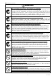
●Handling Precautions DANGER Unplug Unplug Unplug Unplug Unplug NEVER pull apart If any overheating sign is observed, discontinue the use immediately. In the event that smoke, smell, or any other overheating sign is observed, turn its power switch OFF immediately, and remove your plug from outlet. Do NOT try to continue to use this device. To do so in spite of clear signs of malfunction invites a fire, an electric shock hazard, or a serious damage.
DANGER Avoid Avoid Do NOT place any potentially-hazardous things on this device. Do NOT place any things on the device which may, if it gets into the inside of the body, damage the inner parts of the device (such as a flower pot, glass, cosmetics, a container filled with liquids or chemicals, as well as small metal parts, etc.). If tumbled, the liquids inside the bottle, etc. may get into the chassis, causing a fire or an electric shock accident. Do NOT damage the power cord.
This device complies with Part15 of the FCC rules. Operation is subject to the following two conditions: (1) This device may not cause harmful interference, and (2) This device must accept any interference received, including interference that may cause undesired operation. RESTRICTION FOR USE Avoid irregular signal interface. Do not attempt irregular signal interface other than specified.
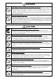
OTHER INSTRUCTIONS Do NOT use power other than specified Be sure to use DC12V power supply. The camera is designed to work only under the specified voltage. Do NOT attempt to drive the camera with the power other than DC12V. Operating the camera under power other than DC12V invites a fire or an electric shock hazard. Avoid intensive light Do NOT expose the camera’s image-pickup-plane to sunlight or other intense light directly.
1. PRODUCT DESCRIPTION Model CS3950D is an integrated type B/W CCD camera with a XGA format all-pixel-data readout CCD. The model is suited for high-speed, high-resolution image processing use. Its compact, light-weight body is ideal for system integration. 2. FEATURES (1) All pixel's data readout With its built-in all-pixel-data-readout CCD, this model can read out image-data just in approximately 1/30 sec. A frame-shutter reads out all data even under RTS (Random Trigger Shutter) mode.
4. OPTION UNIT (1) DC SYNC IN cable ············Model name : CPRC3700 [2m,3m,5m,10m] (2) Camera adapter ···················Model name : CA170 (3) Camera-mounting kit············Model name : CPT *Contact your dealer / distributor for details of option units. *Conformity of an option part and EMC conditions About the conformity of EMC standard of this machine, it has guaranteed in the conditions combined with the above-mentioned option part.
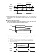
(a)Non-reset mode (Under internal sync / external sync --- Consecutive VD IN) Exposure starts at the timing of TRIG signal IN. After each exposure is completed, the camera outputs video at each next VD IN timing. Automatically returns to normal shutter if fixed H level (after approx.
Automatically returns to normal shutter if fixed H level (after approx. 1/6s) TRIG IN not acceptable for 1V after mode chenge TRIG IN (Positive) CCD Exposure Exposure time (E-shutter speed or pulse width) VIDEO OUT Definite VD,V-SYNC pause during standby VD,V-SYNC output for 1V only WEN OUT (Standard) Normal shutter Random trigger shutter Normal shutter Exposure time delay under RTS When the RTS is active, both in FIX mode and PULSE W mode, there is a time delay of approximately 1.
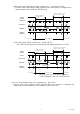
(5) Partial-scan mode selection (Camera rear-panel DIP SW) Switches partial-scan mode Note: Sometimes phenomenon called as “whiteout” occurs at the top of the screen when there is strong incident light entering in the wide area of a CCD, however, this is not a malfunction. If this occurs, reduce the amount of incoming rays. (5-1)1/2 Partial-scan --- Screen center 1/2 readout Only the center portion of 344H out of the total effective lines 768H (excluding BLK time) is read out.
(5-2)1/4 Partial-scan --- Screen center 1/4 readout Only the center portion of 137H out of the total effective lines 768H (excluding BLK time) is read out. Available both under external / internal mode. 137H High-speed transfer 316H Normalspeed transfer Normalspeed transfer 137H High-speed transfer 315H ■Under normal shutter (Electronic shutter OFF) Notes: * Under ext. sync, the ext. VD should be 1V = 193H. ** Under normal shutter, set the rear-panel DIP SW #5, #6 in OFF.
6. SPECIFICATIONS [Basic spec] (1) Image sensor Total pixels Active pixel Video output pixels Scanning area Unit cell size (2) TV system (3) Scanning lines (4) Interlace (5) Sync system (6) Video output (7) Resolution (8) S/N (9) Illumination (10) Gain (11) Gamma (12) White-clip level (13) Power source (14) Power consumption [Internal sync spec] (1) Base clock frequency (2) H sync frequency (3) V sync frequency [External sync spec] (1) Ext.
Exposure-starting-cue signal in random trigger shutter mode LOW level: From 0 through 0.
(3)Restart / Reset Restart / reset available via ext. VD signal (Switching via rear panel DIP SW, Initial OFF) Notes : * The exposure-time (shutter-speed) is determined by ext. VD interval. ** Enabled when rear-panel DIP SW OFF. ***Provide Consecutive HD.
[Mechanical spec] (1) External dimension (2) Weight (3) Lens mount (4) GND / insulation 44 x 29 x 78(D) mm (Not including protrusion) Refer to the attached external view drawing Approximately 130g C mount Circuit GND - Chassis electrically conducted * Combination of CC-mount lens As for the C-mount lens used combining this camera, the projection distance from bottom of the screw should use 8.3mm or less. C-mount lens Bottom of the screw 8.
[Connector pin assignment] (1) Compatible connector (2) Pin assignment Pin No. 1 2 3 4 5 6 7 8 9 10 11 12 Signal (Standard) DC12V GND DC12V VIDEO GND VIDEO OUT HD GND HD IN VD IN TRIG GND NC WEN OUT TRIG IN VD GND HR10A-10P-12S (Supplied by HIROSE ELEC.) Connector pin layout ① ② ⑨ ⑪ ③ ⑧ ⑩ ⑫ ④ ⑦ ⑥ ⑤ 12 pin male Picture Rear-panel camera connector (Rear-view) Notes : *Before connecting / disconnecting the connector, make sure the camera power is OFF. **For board connection, check compatibility.
[Switch setting] (1) CCU rear-panel DIP SW No. 1 2 3 4 5 6 7 8 Function OFF E-shutter-speed (SHUT) 9 Notes: ON See shutter-speed table (Table 1) Shutter mode (SMODE) Partial scan (PART) SHUT See shutter-mode table (Table 3) See partial-scan table (Table 2) Positive (Rising edge) TRIG polarity Negative (Falling edge) SMODE *Initial factory setting: All OFF **Set No.9 OFF when TRIG IN OPEN.
[Relative Spectrum Response] *Including lens characteristics, Excluding light source characteristics [Optical black characteristics] 2 Effective Image Area V 779 788 7 1034 3 40 1077 H Total pixels : 1077(H) x 788(V) Effective pixels : 1034(H) x 779(V) Optical black Horizontal : 3pixels --- 40pixels Vertical : 7pixels --- 2pixels 13 D4133738B
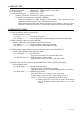
± 0.5µ µs INT HD 102CLK (3.46µ µs ) 5CLK 1 0 2 9 1 0 3 0 40CLK 1 0 3 4 O B 1 164CLK 29CLK O B 4 0 D 1 5CLK D O O O 1 2 B B B 9 1 2 3 14 Dummy Opt. pixels Blk. H. trans. pause Opt.Blk. 3CLK 1024CLK 1 0 2 9 5 6 Effective pixels = 1034CLK V-OUT Effective pixels CAM VIDEO OUT H. blanking 246CLK(8.34µ µs ) H.SYNC 22CLK (0.75µ µs ) 73CLK (2.47µ µs ) 151CLK (5.12µ µs ) Horizontal scan (1H) 1270CLK(43.05µ µs ) D4133738B WEN OUT 5CLK 1024CLK (34.71 µs ) 1 0 3 0 1 0 3 4 7.
(2) V rate timing EXT VD IN 1H delay 27 28 7 8 9 10 35 26 6 34 25 5 33 24 4 32 23 3 31 22 2 30 21 OB OB OB OB OB OB OB 1 29 20 18 19 17 16 15 14 13 12 11 9 10 8 7 6 5 4 2 1 796 795 794 3 9H(387μs) INT VD INT HD Dummy 7H 777 777 778 VIDEO OUT WEN OUT (Standard) 779 OB OB OB 11 12 13 14 15 16 17 28H(1205μs) V.Blanking 1H 768 1V=796H Ext. VD – Ext. HD phase difference EXT VD IN EXT HD IN TP2 TP1 INT VD TP1 : 10.0 us TP2 : 5.
8.
Head Office: 7-1, 4 chome, Asahigaoka, Hino-shi, Tokyo, 191-0065, Japan (Overseas Sales Department) Phone: +81-42-589-8771 Fax: +81-42-589-8774 URL: http://www.toshiba-teli.co.jp The design and specification is subject to change without notice.