CCD B/W CAMERA CS4000B/BC SERIES Specifications CONTENTS 1. FEATURES 2. PRECAUTION 3. CAMERA HEAD&CAMARA CABLE 4. CONSTITUTION 5. SPECIFICATION 6. EXTERNAL VIEW ・CAMERA CONTROL UNIT ・CAMERA HEAD ・CAMERA CABLE ・CAMERA MOUNTING KIT(OPTION) Page 1 1 2 3 3 9 This user's manual is manufactured from recycled paper.
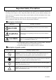
Important Safety Precautions The main unit and the user's manual of the product provide information on important contents that will help prevent injury to those using the product and others, prevent property damage, and ensure safe use of the product. Please make yourself familiar with this information before using your CCD camera. Make sure you understand the meaning of the indications and graphic symbols shown below before reading this manual. Be sure to observe the precautions indicated.
●Handling Precautions (Camera Control Unit) DANGER Unplug Unplug Unplug Unplug Unplug NEVER pull apart If any overheating sign is observed, discontinue the use immediately. In the event that smoke, smell, or any other overheating sign is observed, turn its power switch OFF immediately, and remove your plug from outlet. Do NOT try to continue to use this device. To do so in spite of clear signs of malfunction invites a fire, an electric shock hazard, or a serious damage.
Avoid Do NOT supply any power other than specified. This device is designed to work only under specified voltage. Do NOT attempt to supply the device with power other than specified. Supplying the device with unspecified power invites a fire or an electric shock hazard. ●Handling Precautions DANGER Do NOT place the device unstably. Do NOT place the device on an unstable table, sloped ground, etc.. Make sure that the device do not fall nor roll over to prevent an accident.
●Handling Precautions CAUTION Unplug Unplug the power-plug when the your device is not in use. For safety, make sure to unplug the power-plug before you give your device a cleanup, or when it is not used. Keeping the power-cord connected might invite a fire or an electric shock hazard. Avoid Do NOT expose your device to direct sunlight, nor intensive heat. Do NOT place this device where it is exposed to direct sunlight, or in a high temperature condition.
●Handling Precautions (Camera-head) DANGER NEVER pull apart Do NOT disassemble this device. Do NOT attempt to pull apart, repair, or modify the device on your own. To do so might lead to a fire or an electric shock accident. Contact us or the dealer/distributor from which you purchased the device for repair/modification. CAUTION Avoid Avoid Do NOT connect/disconnect connectors before turning power off. Make sure to check the CCU power is OFF before connecting/disconnecting connectors.
RESTRICTION FOR USE 1. Avoid irregular signal interface. Do not attempt irregular signal interface other than specified. Under signal interface other than recommended/specified in this instruction manual, the device might fail to exert the maximum performance. In much worse case, if you continue to use your device under incorrect signal interface, part(s) of inner circuits might burn down.
Avoid liquid Avoid placing the camera where it is likely to be splashed with water or any other fluids. Operating the camera with its inner parts/circuits in a wet condition might cause a damage or an electric shock accident. About camera cable The connector of the camera cable is in “screw-coupling” lock structure. Improper cramping might cause image noise. Be sure to give it a good cramping to avoid noise.
1. FEATURES (1) Compact and light weight camera head. (2) Equipped with AGC (Automatic Gain Control) which allows wide dynamic range from bright to dark subjects. (3) Equipped with RTS (Random Trigger Shutter) which allows free timing capture with stable SYNC. (4) Available external SYNC (HD/VD, VS, SYNC) operation. 2. PRECAUTION (1) This equipment should be used with DC12V only. To prevent electric shocks and fire hazards, do not use any other power source.
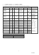
3. CAMERA HEAD & CAMERA CABLE The constitution (the combinations of the camera head and the camera cable) is as following. Camera cable TV system CCD Size CSH4200B CSH4200BC EIA CCIR CSH4300B CSH4300BC Camera cable Appearance of the camera head Appearance Lens mount Type 1/2 φ17mm M15.5 P0.5 (male screw) Round type EIA CCIR Type 1/3 φ12mm M10.5 P0.5 (male screw) Round type CSH4301B CSH4301BC EIA CCIR Type 1/3 φ12mm M10.5 P0.
4. CONSTITUTION (1)Camera control unit 1 (2)Accessories Operation manual 1 (3)Option ① Each camera head ② Camera cable:CPRC4000B-03(3m),-05(5m) ③ Extension camera cable:CPC4000B-07J(7m) ④ Power adapter ⑤ Power cable(Both ends 12P connector):3m, 5m, 10m ⑥ Cable for power supply(VIDEO,HD,VD,SYNC,WENOUT、TRIGINPUT) ⑦ Lens ⑧ For DC INPUT CONNECTOR ⑨ C mount Adapter About the option part and EMC This camera guarantee combination with option part . EMC is not guarantee incase with use non-designate option part.
・Active image area (CSH4200B,CSH4200BC) (CSH4301B、CSH4310B□-□□) (CSH4301BC、CSH4310BC□-□□) (CSH4401B□- □□) (3) Number of scanning lines (EIA) / (CCIR) (4) Scanning system (5) Synchro system (6) Aspect ratio (7) Illumination ・Standard (CSH4200B,CSH4200BC) (CSH4301B、CSH4310B□-□□ CSH4301BC、CSH4310BC□-□□) (CSH4401B□-□□) ・Minimum (CSH4200B, CSH4200BC) (CSH4301B、CSH4310B□-□□ CSH4301BC、CSH4310BC□-□□) (CSH4401B□-□□) (8) Video output 6.5×4.85mm(1/2Type) 4.8×3.6mm(1/3Type) 3.65×2.
(18) External sync input ・Input level HD・VD,SYNC VS ・Input impedance ・Scanning system ・Polarity ・Frequency (EIA) (CCIR) ・Scanning lines (EIA) /(CCIR) ・Phase different HD・VD/SYNC/ VS 2~6V(p-p)/10kΩ、2~4V(p-p)/75Ω 1.0V(p-p) (Sync:0.3V(p-p)) High/75Ω 、Selectable by rear SW setting 2:1 interlace Negative fH =15.734kHz±1%, fV =2fH/525 fH =15.625kHz±1%, fV =2fH/625 525lines/ 625lines The difference in phase between the falling edge of VD and that of HD is shown in the figure below.
② CLOCK ・Output level ・Frequency (EIA) (CCIR ) 2.0±0.3V(p-p)(on no-load condition) 14.31818MHz±100ppm(on no-load condition) 14.18750MHz±100ppm(on no-load condition) ③ WEN On operate random shutter mode, WEN put out from the fall time of VD to the fall time of VD under put out video signal..
(29) Connector Pin Assignment ・Power/Video connector・・・・・Compatible plug :HR10A-10P-12S(Manufactured HIROSE ELEC) Pin External sync Internal sync No. HD・VD VS/SYNC Restart Reset 1 GND GND GND GND 2 +12V +12V +12V +12V 3 GND GND GND GND 4 Video OUT Video OUT Video OUT Video OUT 5 GND GND GND GND 6 HD INPUT HD INPUT HD OUT (*1) 7 VD INPUT R.
(30) Ambient condition ・Performance assurance Temperature Humidity ・Operation assurance Temperature Humidity ・Storage Temperature Humidity 0℃~40℃ 20~80% (No condensing) -10℃~50℃ 20~80% (No condensing) -20℃~60℃ 20~95% (No condensing) 8 D4134844A
6.
(2)CAMERA HEAD DRAWING CSH4200B, CSH4200BC CSH4300B, CSH4300BC CSH4310BW/X/Y/Z-□□ CSH4310CW/X/Y/Z-□□ CSH4310BV-□□ CSH4310BCV-□□ 10 D4134844A
CSH4301B, CSH4301BC CSH4410BW/X/Y/Z-□□ (3)CAMERA CABLE CPRC4000B-03/05 Connector 1 HR25-8TP-14S Connector 2 HR25-9TP-16P Cable length 3/5 m CPC4000B-07J Connector1 HR25-9TJ-16S Connector 2 HR25-9TP-16P Cable length 7m 11 D4134844A
(4)CAMERA MOUNTING KIT(OPTION) Mount kit:CSH4200B/BC Mount kit: CSH4300B/BC 12 D4134844A