
Telephone User Manual


Strata CTX670 Installation
Remote Expansion Cabinet Unit
Strata CTX I&M 06/04 4-55
Strata CTX670
Installation
Remote Expansion Cabinet Unit
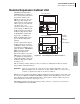
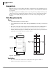
The RRCU1A PCB enables a
CTX670 Expansion Cabinet to
be located up to three kilometers
from its Base Cabinet. One
RRCU1A connects to up to two
ribbon-type Data Cables and
applies the inter-cabinet signal to
a fiber-optic pair. One fiber pair
can support one or two
expansion cabinets in one remote
location using one RRCU1A in
the Base Cabinet and another in
the Remote Expansion Cabinet.
A CTX670 Base Cabinet will
support up to six RRCU1A
PCBs. A CTX670 will support
up to six Remote Expansion
Cabinets.
An inter-cabinet Data Cable in
the Base Cabinet is attached to
an RRCU1A which converts the
signal and uses an LED source to
apply the signal to 500 MHz/km
multi-mode fiber. Another
RRCU1A in the Remote
Expansion Cabinet receives the
LED signal, converts it back to
its original form and applies it to
a ribbon Data Cable connected to
the Remote Expansion Cabinet.
See Figure 4-38.
This is a hardware solution and has no effect on software or administration. Remote cabinets
support all line and trunk interfaces.
Important! Network clock signals can only be derived from digital trunk PCBs, such as the
RDTU and RPTU, that are installed in the Base Cabinet (Master) location. Do not
install these digital trunk cards into the Remote Cabinets.
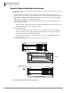
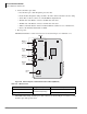
RRCU1A cards are used at both the Base (Master) and Remote (Slave) Cabinet locations. The card
set consists of an RRCU1A PCB and its ROMS1A daughter board. The RRCU1A connects to the
inter-cabinet Data Cables, holds the Remote/Slave option jumpers, and has an RS-232C port for
monitoring the fiber connection. (See Figure 4-41.)
The ROMS1A daughter board holds an SC-type fiber connector, a connector for control of two
8-circuit DPFT units, and status LEDs.
Fiber Optic
Connection
Up to
3 Kilometers
(Dealer Supplied)
Expansion Cabinet (2)
Base Cabinet
Remote Expansion Cabinet (4)
MSBU
Remote Expansion Cabinet (3)
5820
1 (M1)
2 (S1)
3 (M2)
2
3
4
5
6
7
Optical Module
4 (S2)
1 (M1)
2 (S1)
3 (M2)
Optical
Module
4 (S2)
Local CTX Cabinets
Remote CTX Cabinets
Figure 4-38 Remote Expansion Cabinet Connection