
Telephone User Manual


Rack Mount Cabinets
Remote Expansion Cabinet Unit
5-36 Strata CTX I&M 06/04
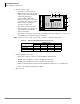
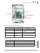
6. Connect the data cables
• At the Base Cabinet, attach an
BDCL1A data cable from the data
cable connector on the back of the
cabinet (shown right) to
Connector M1 or M2 on the
RRCU card. (Cables are provided
according to the connectors on the
RRCU card to which they are
attached, see Table 5-6.)
• The cabinet connected to M1 in
the base emerges on connector S1
of the RRCU1A at the Remote
Expansion Cabinet.
• The cabinet connected to connector M2 of the RRCU in the base emerges on connector S2
of the RRCU1A at the Remote Expansion Cabinet.
Note Coil the excess tie it with a tie wrap. Be careful not to bind the cable tightly.
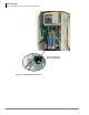
7. Connect the fiber optic cables
• Attach fiber to the SC connectors on the ROMS1A daughterboard.
• The TX side of the Master connects to the RX side of the slave.
• The RX side of the Master connects to the TX side of the slave.
• TAIS recommends that the cables be marked within the cabinet for ease of maintenance.
• Observe the minimum bend radius of 30mm.
8. Restore power.
Table 5-6 Remote Cabinet Data Cables and Connectors
Data Cables
RRCU Connectors
M1 S1 M2 S2
BDCL1A-MS1 X X
BDCL1A-M2 X
BDCL1A-S2 X
X=applies to connector
7077
CAB
2
CAB
5
CAB
6
CAB
3
CAB
4
CAB 5
CAB 2 CAB 3 CAB 4
CAB 6
CAB 7
To RRCU1A card
on front of cabinet
CAB
7
BDCL1A cable