
Telephone User Manual


PCB Installation
REMU2A – Tie Line Unit
Strata CTX I&M 06/04 6-33
PCB Installation
Note The “GND” position is used to connect PEMU circuits back-to-back on premises only, 1000
feet maximum (E&M lead wires must be crossed).
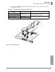
5. Insert the PEMU (component side facing right) into the appropriate slot and apply firm, even
pressure to ensure proper mating of connectors.)
6. After installing, gently pull the PEMU outward. If the connectors are properly mated, a slight
resistance is felt.
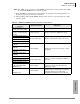
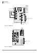
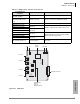
Table 6-16 REMU2A and REMU1A Controls, Indicators, and Connectors
Control/Indicator/
Connector
Type of Component Description
Tie trunk circuits 1~4
(CD102, 202, 302, and 402)
Red LED Lights to indicate that Tie line is in operation.
E&M Tie trunk connector
circuits 1~4 (J101, 201, 301,
and 401)
Modular connector Interface connector for E&M Tie line circuit.
Pad switch SW101 (circuit 1)
2-position slide switch Enables -3 dB signal level drop for line circuit.
Pad switch SW201 (circuit 2)
Pad switch SW301 (circuit 3)
Pad switch SW401 (circuit 4)
TYP1/TYP2 jumper plugs
P102/104
3-terminal jumper
Enables line circuit to be set for Type 1 or Type
2 signaling.
TYP1/TYP2 jumper plugs
P202/204
TYP1/TYP2 jumper plugs
P302/304
TYP1/TYP2 jumper plugs
P402/404
2W/4W switch 102 (circuit 1)
2-position slide switch
Selects 2- or 4-wire configuration for E&M Tie
line circuit.
2W/4W switch 202 (circuit 2)
2W/4W switch 302 (circuit 3)
2W/4W switch 402 (circuit 4)
TYP1,2/DC5 jumper plugs
P105, P205, P305, P405
(REMU2A only)
3-terminal jumper
For most countries, use the default position
(TYP1,2). In the U.K. and Japan, place the
jumper plug on DC5.
Mu Law/A Law jumper plug
P2
(REMU2A only)
3-terminal jumper
Do not move the jumper plug which is in the
default for the U.S. and Canada. For countries
requiring A Law, place the jumper plug
(provided in the PCB box) on the A Law side.