
Telephone User Manual


ISDN Interfaces
BPTU and RPTU Cabling
7-12 Strata CTX I&M 06/04
Cable Installation
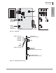
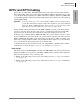
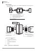
Use the Toshiba RPRI cable kit to connect the BPTU or RPTU PCB to a CSU. Install the kit as
shown in Figure 7-6.
.
Figure 7-6 Detailed Pinouts for ISDN PRI Cabling
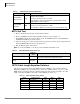
Network Jack/BPTU or RPTU Modular Jack
Pin Function
1 Tip – Receives from the network (NT – TE)
2 Ring – Receives from the network (NT – TE)
3 Not Used
4 Tip – Transmits to the network (TE – NT)
5 Ring – Transmits to the network (TE – NT)
6 Not Used
7 Not Used
8 Not Used
ISDN PRI
Network
Jack
CSU
DB15
(female)
DB15
(male)
BPTU
or
RPTU
6645
A
B
C
D
E
RJ45
Item Description
A
1
1. Cable A and D are straight-pinned data cables, not cross-
pinned telephony cables.
Fifteen feet of CAT5 unshielded cable
B One DB15 modular adapter (CSU to network jack)
C One DB15 modular adapter (CSU to RPTU)
D
1
Thirty feet of CAT5 shielded cable
E One Ferrite core
C
S
U
1
2
3
4
5
6
7
8
1
2
3
4
5
6
7
8
1
2
3
4
5
6
7
8
1
2
3
4
5
6
7
8
CSU Local Power
Adapter
Network
Interface
Jack
RJ48-C
or
RJ48-X
(8-pin
Modular)
1-T1
2-R1
3-
4-R
5-T
6-
7-Nu
8-Nu
1-T1
2-R1
3-
4-R
5-T
6-
7-Nu
8-Nu
BPTU or
RPTU
8-pin
Modular
Jack
1
2
3
4
5
6
7
8
3
11
9
1
1
2
3
4
5
6
7
8
3
11
9
1
3-T1
11-R1
3-
9-R
1-T
3-T1
11-R1
3-
9-R
1-T
CSU
DB15
Male
CSU
DB15
Female
Toshiba-supplied 8-wire modular
cord, straight-through pinning
(15 ft. CAT5, unshielded)
Toshiba-supplied 8-pin modular
cord to DB15 female adapter
Dealer-supplied CSU
Toshiba-supplied 8-pin modular
to DB15 male adapter
Toshiba-supplied 8-wire
modular cord, straight-through
pinning (30 ft. CAT5, shielded)
Toshiba-supplied Ferrite core
6646