
Telephone User Manual


ISDN Interfaces
RBSU/RBSS Interface Units
Strata CTX I&M 06/04 7-21
ISDN Interfaces
RBSU/RBSS Premise Wiring Guidelines
Power Failure Terminal Screws
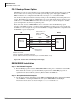
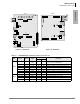
TB1 and TB2 are the connecting points that interface a pair of dry contacts that can be used for
power failure switching purposes (see Figure 7-14 for the locations). When the Strata CTX system
has power (from AC source or batteries) there is a short circuit across TB1 and TB2. In the event
of no power to the Strata CTX, there is an open circuit across TB1 and TB2. The specifications for
TB1 and TB2 contacts are:
• Maximum switchable voltage: 30VDC
• Maximum switchable current: 80mA
• Short circuit resistance: Approximately 15 ohms
Grounding Terminal Screws
TB3 is a screw terminal that can be used to connect a ground wire to the RBSU PCB (see Figure
7-14 for the location). This ground enables the RBSU/RBSS to meet Electro Magnetic
Compatibility (EMC) requirements. The RBSU complies with EMC requirements without
grounding TB3 on the RBSU, so it is not necessary to connect a ground wire to TB3.
BRI Wire Type Recommendations
CAT3 or CAT5 wire is recommended for ISDN BRI customer-premises wiring. While the ISDN
BRI signal works for some distance over almost any wire that is suitable for analog voice service,
better wire enables longer runs. CAT5 provides better 100-ohm impedance matching (at little extra
cost) between the RBSU/RBSS circuit and the station Terminal Equipment (TE-1).
Normally the CAT3 or CAT5 wiring does not have to be shielded when used for ISDN BRI
premises wiring. However, the RJ45 jacks on the RBSU/RBSS BRI circuits are shielded and
provide a ground shield in the event that shielded modular plugs and cable are used.
Note If using shielded cable and plugs, cable runs should only be grounded at the Strata CTX
RBSU/RBSS, RJ45 jacks. To prevent ground loops, do not ground both ends of shielded
cable runs.
RBSU/RBSS BRI Cable Jacks and Connectors
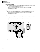
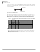
In the U.S., the standard connector for ISDN equipment is the eight-pin RJ jack. Patch cables have
eight-pole plugs at both ends. The same pinout applies to both ends of an ISDN cable, which is the
practice of the data world. This means that a flat untwisted cable with an RJ modular plug at both
ends will have the locking tab of the plug on one end, “up;” and on the other end, “down,” as
shown in Figure 7-15.
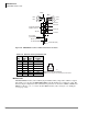
Note This is the opposite of telephony “silver satin” cables which have locking tabs on both ends
facing the same direction. Telephony cables cause the pins at either end to crossover while
data cables provide a straight through pin-to-pin connection between modular jacks.