
Telephone User Manual


T1
T1
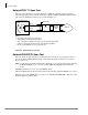
RDTU1 & 2 - T1 Interface Unit
Strata CTX I&M 06/04 8-17
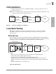
Alarms are used to indicate potentially serious telephone network problems. Example: when
monitoring a T1 network, if a Blue or Yellow alarm is indicated, it can be concluded that there is a
cable fault or some other serious transmission impairment.
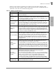
Table 8-12 RDTU1 and 2 LED Functions
Alarm LED Function
Frame Alarm
(FALM)
Turns On steady if the RDTU has not achieved synchronization or when the span
cable is not connected.
Multi-Frame Alarm
(MFALM)
LEDs turn On steady if the RDTU receives the 1.554 mbs T1 carrier from the far
end, but has not achieved Frame synchronization or when the span cable is not
connected. Also, if the RDTU is set for SF and the far end is sending ESF (or vice
versa), the MFALM LED will be On steady.
Red Alarm (FALM
and MFALM)
When FALM and MFALM are both On steady, it’s a Red alarm condition. This
means the RDTU does not detect a proper carrier signal (1.544 mbs T1) on its
receive pair and the RDTU is not synchronized. During a Red alarm condition, the
RDTU turns the BSY LED On steady and attempts to send a Yellow alarm signal
(RDTU YALM LED flashes) to the far end T1 circuit.
Ye l l o w A l a r m
(YALM)
When the far end network or CPE T1 does not detect the RDTU transmitted 1.544
mbs T1 carrier signal on its receive pair the far end, T1 sends a Yellow alarm signal
pattern to the RDTU. The RDTU should turn on the YALM LED (the YALM repeats
the signal it receives from the far end—flashing or steady). If the RDTU does not
receive the far end carrier signal, the RDTU sends the Yellow alarm signal to the far
end and causes the BSY and YALM LEDs to flash.
Blue Alarm (BALM)
The Blue alarm, also known as the Alarm Indication Signal (AIS), is detected by the
RDTU. This signal is sent by the Far End Network equipment to RDTU when it
loses the carrier from a Network T1 circuit (other than RDTU). This signal assures
that the RDTU maintains synchronization when there is a problem between two
Network Nodes. The RDTU BALM also lights if the far end sends a Blue alarm
signal during loop back. The RDTU sends a Blue alarm signal when loop-back test
is being performed.
Primary
Synchronization
(PSYNC)
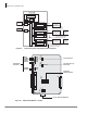
See Figure 8-6 on page 8-16 – If one RDTU PCB is assigned as the Primary Timing
T1 PCB in Program 105, the PSYNC LED of this RDTU PCB flashes when it is
synchronized with the far end T1 span line clock provider.
If the Primary RDTU is not synchronized with the clock provider, the PSYNC LED
will be On steady. The SSYNC LED of the Primary sync RDTU PCB should always
be Off. The Primary sync RDTU PCB synchronizes the RTCU (time-switch) to the
clock signal it receives from the T1 span circuit to which it is connected. The RTCU
then synchronizes the Strata CTX PCM talk path (time-switch) to the far end PCM
talk path.
Secondary
Synchronization
(SSYNC)
If an RDTU PCB is assigned as the Secondary time T1 PCB in Program 105, its
SSYNC LED will be On steady (standby mode) when the Strata CTX is
synchronized to the Primary T1 clock provider.
In the event Primary synchronization is lost (4 out of 12 consecutive frame timing
bits are in error), the Strata CTX switches from synchronizing to the Primary RDTU
span line clock to the span line clock connected RDTU designated as the
Secondary Timing Reference. When the Strata CTX is synchronized to the
Secondary Reference RDTU, the PSYNC LED on the Primary Reference RDTU
turns on steady and the SSYNC LED on the Secondary Reference RDTU will flash.
Run Free
(PSYNC/SSYNC)
If the RDTU PCB is the clock provider to the Far-end T1 span circuit, both the
PSYNC and SSYNC LEDs are always Off.