
Telephone User Manual


T1
T1
CSU Installation
Strata CTX I&M 06/04 8-19
CSU Installation
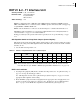
³ Install the CSUs and wire them to the RDTU and NIU or customer premises T1 circuit, as
required (see Figure 8-9).
Note Before connecting the CSU to the Telco line, notify the T1 provider. You should also notify
the T1 provider before disconnecting the CSU.
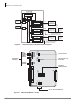
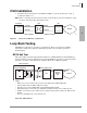
Figure 8-9 CSU Local and Network Loop Back Tests
Loop Back Testing
The RDTU provides three loop back test configurations. These loop back tests should be
performed as required in conjunction with CSU loop back tests (see CSU loop back test
documentation).
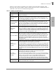
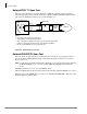
RDTU Self Test
This test should be performed upon initial installation of a RDTU PCB. Program the RDTU per
the Strata CTX Programming Manual; then perform the RDTU loop back test, per the instructions
in Figure 8-10, before connecting the far end (CSU, Network, or CPE) T1 span line.
Figure 8-10 RDTU Self Test
Transmit
Receive
CSU NIU
Receive
Transmit
Local Loop Back Network Loop Back
CTX RDTU
Network
5801
RDTU Self Check
T1 Framer IC Chip
P1
Network
Interface
Unit
CSU
Remove NDTU Cable
P2
RDTU3 (DS2155)
RDTU1/2 (MM8976B)
Network
6688
Notes
● RDTU1 & 2, move P1 and P2 to On (see Figure 8-7); RDTU3 move SW8 & SW9 to On.
● Remove NDTU cable from RDTU amphenol connector.
● After about 12 seconds, all RDTU LEDs (except PRI/SEC SYNC) turn Off.
● Appropriate Primary or Secondary sync. LED flashes if RDTU is Primary or Secondary reference.
● If RDTU is not a Primary or Secondary reference, then the Primary and Secondary sync LEDs should
turn Off.
● Do not use the RDTU3A as a clock extraction unit.