
Telephone User Manual

IP Telephony and QSIG Over IP
Pre-installation Guidelines
9-6 Strata CTX I&M 06/04
Step 2: Install BIPU-M2A
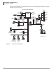
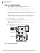
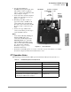
1. Make sure the BIPS1A is installed onto the BIPU-M2A PCB (see Figure 9-2).
2. Install the BIPU-M2A into one of the following slots:
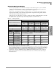
• CTX100 Base and Expansion Cabinet slots (1~8, 8 or 16 IPTs per slot per Program 100)
• CTX670 Base Cabinet slots (1~8, 8 or 16 IPTs per slot per Program 100)
• CTX670 Expansion Cabinet slots (1~6, 8 or 16 IPTs per slot per Program 100)
3. Follow the procedure in “Worksheet 7 – System Power Factor Check” on page 2-42 to check
the cabinet power factor.
4. Power up the system.
5. Program the CTX per the instructions in the Strata CTX Programming Manual, refer to the
chapter titled “IP Telephone Programming” and “Appendix A – “Applications, Tips, and
Tricks.”
Connect BIPU-M2A to LAN or VPN Server
1. Plug one end of a straight-through CAT5/5E/6 LAN cable into the RJ45 Ethernet port on the
BIPU-M2A PCB in the CTX. (See Figure 9-2.)
2. Plug the other end of the BIPU-M2A CAT5/5E/6 LAN cable into a LAN or server jack (see
Figures 9-8 and 9-9.)
Note The BIPU-M2A or Q1A-switch cables are straight-through cables.
Figure 9-2 BIPU-M2A or BIPU-Q1A PCB ZZ
PTC1111-01
0211
YCL
V.01
BIPU-M2A
or
BIPU-Q1A
6632
12345678
HB
RD LINK SD
Reset
RJ45 Ethernet Port
RS232
Maintenance Jack
Factory
Installed
Heart Beat LED
P601
P2
P702 P704
P701
P703
Status/Alarm LEDs
For engineering
purposes only
Ethernet Port LEDs
RD
LINK
SD
P705
P706 P708
P707
BIPS1A - /16
Backplane Connector