
Telephone User Manual


CTX28 Installation
Installing the CTX28 Cabinet
Strata CTX I&M 06/04 1-15
CTX28 Installation
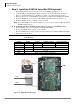
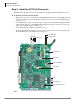
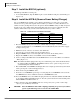
Table 1-8 GCTU
Control/Indicator/
Connector
Type of Component Description
P1 60 pin connector GETS Interface
P2 60 pin connector BSIS Interface
P501 SmartMedia house SmartMedia interface
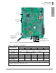
P601 Jumper plug
Must always be in the “ON” position to maintain
customer data
P801 RCA Jack Paging interface and BGM/MOH interface
P901 2 pin screw terminal Relay contact
P902
44-pin male DIN
connector
CTX28 Back plane connector
P903
44-pin male DIN
connector
CTX28 Back plane connector
CD101 LED Processor operation indication
CD501 LED SmartMedia access indicator
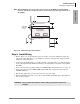
CD908 LED
Green DC power indicator for CTX28 system. Shown
on front cover (see Figure 1-3).