
Telephone User Manual


MDF PCB Wiring
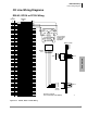
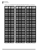
Station Wiring Diagrams
Strata CTX I&M 06/04 10-11
MDF PCB Wiring
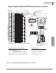
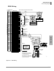
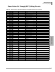
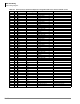
RDSU Wiring
Figure 10-7 RDSU Wiring
1
2
3
4
5
6
7
8
9
10
11
12
13
14
15
16
17
18
19
20
21
22
23
24
25
26
27
28
29
30
31
32
33
34
35
36
37
38
39
40
41
42
43
44
45
46
47
48
49
50
1
2
3
4
5
6
7
8
9
10
11
12
13
14
15
16
17
18
19
20
21
22
23
24
25
26
27
28
29
30
31
32
33
34
35
36
37
38
39
40
41
42
43
44
45
46
47
48
49
50
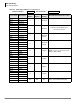
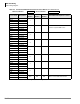
W-BL
BL-W
W-O
O-W
W-GN
GN-W
W-BR
BR-W
W-S
S-W
R-BL
BL-R
R-O
O-R
R-GN
GN-R
R-BR
BR-R
R-S
S-R
BK-BL
BL-BK
BK-O
O-BK
BK-GN
GN-BK
BK-BR
BR-BK
BK-S
S-BK
Y-BL
BL-Y
Y-O
O-Y
Y-GN
GN-Y
Y-BR
BR-Y
Y-S
S-Y
V-BL
BL-V
V-O
O-V
V-GN
GN-V
V-BR
BR-V
V-S
S-V
26
1
27
2
28
3
29
4
30
5
31
6
32
7
33
8
34
9
35
10
36
11
37
12
38
13
39
14
40
15
41
16
42
17
43
18
44
19
45
20
46
21
47
22
48
23
49
24
50
25
Bridging Clips
To RDSU W/Female
Connector
25-Pair Cable With Male Amp Connector
66M150 SPLIT BLOCK
Tip 1
Ring 1
GN
Y
BL
R
BK
W
654321
654321
Voice Mail Port Or
Similar Device
Voice Mail Port Or
Similar Device
RJ11
RJ11
RING
Tip
TIP
Ring
Standard Telephone 2
Standard Telephone 1
Ring 2
Tip 2
GN
Y
BL
R
BK
W
Not Used
Station Cabling Jacketed Twisted Pairs (24 AWG)
T3
R3
T4
R4
Not Used
Not Used
Standard
Telephone
Circuits 3 and 4
available with
optional RSTS
PCB.
Wire the same
as Circuits 1
and 2.
Circuit 6 to DKT 6
or PDIU-DS
Circuit 7 to DKT 7
or PDIU-DS
Circuit 5 to DKT 5
or PDIU-DS
or DDCB
T5
R5
PT5
PR5
T6
R6
PT6
PR6
T7
R7
PT7
PR7
(-) T8 (Voice/Data)
(GND) R8 (Voice/Data)
(-) PT (Add Power)
(GND) PR (Add Power)
Not Used
GN
654321
Y
BL
R
BK
W
34
R8
PT8
T8
PR8
25
PR TR PT
RJ11
Digital
Telephone
Modular
Cord
GND
PR
(-)
T
GND
R
(-)
PT
(See Note)
DPFT
Power Failure
Transfer Box
(J1)
-24VDC
(J1, 25)
DG
(J1, 50)
DG
-24V
1603
Digital Telephone (with or w/o ADM, DSS,
or DDCB. BATI, BPCI, RPCI, and PDIU-DI
are not supported with PDKU.
With the PDKU, 3000-series DKTs function
as 2000-series DKTS: 16 character LCD, no
Spdial or LCD Feature buttons.