
Telephone User Manual


Strata CTX I&M 06/04 12-1
Peripheral Installation
Peripheral Installation 12
This chapter provides information and diagrams for connecting peripheral equipment to the Strata
CTX interface circuits. These interfaces include those listed below:
• Application PC and Server Interfaces
• Strata CTX WinAdmin, ACD, Attendant Console, SMDI and SMDR
• Music-On-Hold/Background Music Interfaces
• External Page with BIOU Interface
• Control Relays with BIOU Interface
• Door Phone/Door Lock with DDCB Interface
• Telephone External Ringer with HESB Interface
• Amplified Page with HESB Interface
• Amplified Page/Talk-Back with HESB Interface
• Power Failure Cut-through with DPFT Interface
• Station Message Detailed Recording
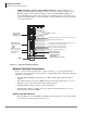
Application PC and Server Interfaces
Application PCs and/or servers are connected to the Strata CTX system via a Network Interface
jack, RS-232 serial ports and/or a Strata CTX modem depending on the application. These
interfaces are provided by the CTX system processor. The network jack and built-in modem are
standard equipment on the CTX670 processor and option PCBs on the CTX100 processor. The
BSIS four-port serial interface is an optional PCB that mounts on the CTX100 or CTX670
processor (see Figure 12-1).
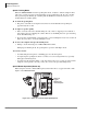
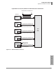
• CTX WinAdmin, Stratagy VM Proprietary Integration, Attendant Console and ACD
Network Interface – These application PC/servers equipped with a standard Network
Interface Card (NIC) connect to the Strata CTX network jack. One network interface jack is
standard on the Strata CTX670, BBCB processor PCB. The AETS option is required on the
CTX100 ACTU processor. This is the only network jack interface on the Strata CTX (see
Figures 12-1~12-4).
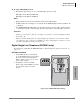
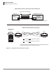
• CTX WinAdmin Modem Interface – CTX WinAdmin PC servers equipped with a modem
can connect the Strata CTX maintenance modem. One built-in maintenance Modem is standard
on the Strata CTX670, BECU processor PCB. An AMDS option PCB is required for CTX100
ACTU processor PCB.The Strata CTX modem supports point-to-point TCP/IP connection to a
CTX WinAdmin PC modem over PSTN telephone lines (see Figure 12-5 for a connection
diagrams).