
Telephone User Manual


Peripheral Installation
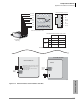
External Page with BIOU Interface
Strata CTX I&M 06/04 12-13
Peripheral Installation
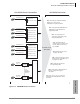
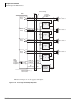
Control Relays with BIOU Interface
Up to two BIOU interfaces can be installed to provide control relays for Night Bell, Night
Transfer, Door Lock and BGM mute control. Each BIOU provides four control relays for a total of
eight relays (max.) per system. Each relay’s function is selected in system programming. BIOU
interfaces can be installed in the main cabinets and/or any remote cabinet (see Figure 12-8).
BIOU control relay contact power ratings are shown below:
• 24 VDC maximum
• 1.0 amperes maximum
CAUTION! BIOU relay contacts are not rated to switch 120/240VAC, connecting these
voltages may result in equipment damage, fire and/or personal injury.
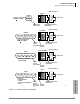
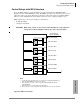
Figure 12-13 BIOU Control Relays
5492
BIOU (1 or 2)
CRR2, Pin 5 (S-W)
CRT2, Pin 30 (W-S)
SW200
Relay 2
B
M
CRT3, Pin 32 (R-O)
CRR3, Pin 7 (O-R)
SW250
Relay 3
B
M
25- Pain Amphenol
Connector Pin Number
M
CRT1, Pin 28 (W-GN)
CRR1, Pin 3 (GN-W)
SW150
Relay 1
B
CRT4, Pin 34 (R-BR)
CRR4, Pin 9 (BR-R)
SW300
Relay 4
B
M
Notes
1. User Relay Service Program 515 to set control relay for Night Bell, Night, Door
Lock, External BGM mute functions as required.
2. Relay functions can open or close contacts by setting Make/Break switches
SW150~SW300.
3. Relay functions are set in Programs 503, 508 and 515.
4. Relay contacts are rated at 24 VDC, 1.0A maximum. Do not connect to 120VAC.