
Telephone User Manual


Strata CTX
Configuration
Strata CTX Configuration
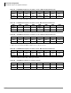
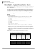
Worksheet 6: Strata CTX670 Cabinet Slots
Strata CTX I&M 06/04 2-39
• Cables are provided according to the connectors on the RRCU card to which they are attached.
See Table 2-53 for connector information.
Step 3: BIOU Interface PCB
• Up to two BIOU PCBs can be installed in any local/remote cabinet slot, except the BIOU may
not occupy a vacant slot adjacent to RDTU, BPTU or RPTU. See “Worksheet 4: Page/MOH/
Control Relay” on page 2-26 for BIOU functions.
Step 4: T1 Digital Line PCBs
•See Worksheet 3: CO Line to determine RDTU PCB requirements.
• RDTU must be placed in designated slots as shown in Table 2-54. The RDTU PCB can provide
up to 16 or 24 T1 lines. The RDTU slot provides 16 T1 lines, an additional eight lines requires
that the cabinet slot adjacent to RDTU be vacant. Up to 11 RDTU PCBs can be installed in a
fully expanded system
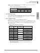
Table 2-53 Remote Cabinet Data Cables and Connectors
Data Cables
RRCU Connectors
M1 S1 M2 S2
BDCL1A-MS1 X X
BDCL1A-M2 X
BDCL1A-S2 X
X = Applies to connector.
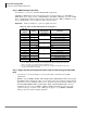
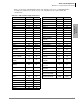
Table 2-54 RDTU PCB Cabinet Slot Configuration
T1 Channels
Needed per
Cabinet
Slots
Needed
RDTU PCBs
Needed
1
1. RDTU PCBs do not have to be installed in the order shown in this table. Example: If only one
RDTU is needed, it can be installed in any RDTU slot shown in the table so long as the slot is
supported by the installed processor.
RDTU cabinet slot placement
1
Base Cabinet
1~16 1
1
S103-RDTU
17~24 2 S104-vacant
2
2. The slot occupied by RDTU supports 1-16 channels; the slot adjacent to RDTU must be vacant
if channels 17 through 24 are needed.
24~40 3
2
S105-RDTU
41~48 4 S106-vacant
2
49~64 5
3
S107-RDTU
65~72 6 S108-vacant
2
Second through seventh
cabinets
1~16 1
1
S_01- RDTU
17~24 2 S_02-vacant
2
25~40 3
2
S_03- RDTU
41~48 4 S_04-vacant
2
49~64 5
3
S_05-RDTU
65~72 6 S_06-vacant
2