E6581281 f TOSVERT VF-AS1/PS1 Option Function Manual DEV002Z-1 * The data given in this manual are subject to change without notice. © Toshiba Schneider Inverter Corporation 2006 All rights reserved.
E6581281 f Contents INTRODUCTION .....................................................................................................................................3 CONNECTION INFORMATION.............................................................................................................4 2.1. CONNECTION SIZES ............................................................................................................................4 2.2. EXTERIOR OVERVIEW .......................................
E6581281 f 3.7. CONTROL SUPERVISOR OBJECT ........................................................................................................31 3.7.1. Control Supervisor Object Class Attributes ..............................................................................31 3.7.2. Control Supervisor Object Instance Attributes..........................................................................32 3.7.3. Control Supervisor Object Common Services ......................................................
E6581281 f 1. Introduction Thank you for purchasing the DeviceNet option “DEV002Z” for the VF-AS1/PS1. Before using the DeviceNet option, please familiarize yourself with the product and be sure to thoroughly read the instructions and precautions contained in this manual. In addition, please make sure that this manual and “Instruction Manual” is delivered to the end user, and keep this function manual in a safe place for future reference or drive/interface inspection.
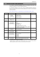
E6581281 f 2. Connection Information 2.1. Connection Sizes Connection Instance I/O Messaging Explicit Messaging Produced 4, 8, or 12 bytes 55 bytes Consumed 4, 8, or 12 bytes 55 bytes Notes - For the Polled I/O connection, if the actual consumed data size is less than the connection instance’s consumed_connection_size attribute, the consumed data will be ignored, but the connection will otherwise produce normally.
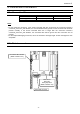
E6581281 f 2.3. Setting a MAC ID number and a network baud rate Configure MAC ID and network baud rate by the Dip switch on the DeviceNet option. 1 2 3 4 Baud rate 5 6 7 8 MAC ID = 1 Baud rate = 125kbps MAC ID • MAC ID configuration The MAC ID must be unique and not match any other device on the network.
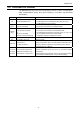
E6581281 f 2.4. DeviceNet LED indicator The DEV002Z option has a two-color (red and green) LED as a means of indicating the MNS (module/network status), which works basically in accordance with DeviceNet specifications. LED Status Item displayed Off Not Powered/Not On–line Lights green. Device Operational AND On–line, Connected Device is not on-line. - The DEV002Z has not completed the Dup_MAC_ID test yet. - The DEV002Z may not be powered.
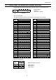
E6581281 f 2.5. Communications-related parameters In a network, VF-AS1/PS1 (DEV002Z) serves as a DeviceNet slave device. The DEV002Z configuration is set by the following parameters. The supported parameters for each drive and their allowable adjustment ranges are defined in the appropriate Electronic Data Sheet (EDS) files. EDS files can be downloaded via the internet from http://www.inverter.co.jp/product/inv/vfas1/dev/index_i.
E6581281 f 3. Object Specifications This section contains the object specifications for all DeviceNet objects currently supported by the “DEV002Z”.
E6581281 f 3.1. Identity Object Class code 0x01. This object provides identification of and general information about the device. 3.1.1. Identity Object Class Attributes Attribute ID 1 Revision 2 3.1.2.
E6581281 f 3.2. Message Router Class code 0x02. The Message Router Object provides a messaging connection point through which a Client may address a service to any object class or instance residing in the DeviceNet interface unit. 3.2.1. Message Router Class Attributes Attribute ID 1 Revision 2 3.2.2.
E6581281 f 3.3. DeviceNet Object Class Code 0x03. The DeviceNet Object provides for the configuration and status of a DeviceNet port. 3.3.1. DeviceNet Object Class Attributes Attribute ID 1 Revision 2 3.3.2. Name Max instance Data Type UINT Access Rules Get UINT Get Description Revision of this object.
E6581281 f 3.4. Assembly Object Class code 0x04. The Assembly Object binds attributes of multiple objects, which allows data to or from each object to be sent or received over a single connection. 3.4.1. Assembly Object Class Attributes Attribute ID 1 Revision 2 3.4.2. Max instance 3 Name Data Access Rules Get UINT Get Description Revision of this object.
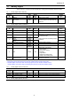
E6581281 f 3.4.5. Assembly Instance Details (f830) 3.4.5.1. Instance 20/70 - DeviceNet Standard (4 bytes, parameter f830 = 0) Byte Bit 7 Bit 6 Bit 5 Bit 4 Bit 3 Bit 2 Bit 1 0 - - - - - Fault reset - 1 2 3 Bit 0 Run forward Drive Reference Speed min-1 (Low byte) * Drive Reference Speed min-1 (High byte) * Fig.
E6581281 f 3.4.5.2. Instance 21/71 - DeviceNet Standard (4 bytes, parameter f830 = 1) Byte Bit 7 Bit 6 Bit 5 Bit 4 Bit 3 Bit 2 0 - Net Ref * Net Ctrl * - - Fault reset 1 2 3 Bit 1 Run reverse Bit 0 Run forward Bit 1 Bit 0 Faulted/ tripped Drive Reference Speed min-1 (Low byte) Drive Reference Speed min-1 (High byte) Fig.
E6581281 f Examples of Instance 21/71 ① Stop Instance Byte 1, 0 3, 2 1, 0 3, 2 15 0 0 0 14 0 0 0 13 0 0 0 12 0 0 0 11 0 0 0 10 0 0 0 9 0 1 0 8 0 1 0 7 0 0 0 6 0 0 0 5 0 0 0 4 0 1 0 3 0 0 0 2 0 0 0 1 0 0 0 0 0 0 0 Hex.
E6581281 f 3.4.5.3. Instance 100/150 - Toshiba Specific (4 bytes, parameter f830 = 2) Byte Bit 7 0 DC braking 1 Command link * Bit 6 ACC1/ ACC2 Frequency link * 2 3 Bit 5 Bit 4 PI off THR2 Bit 3 Preset Speed4 Bit 2 Preset Speed3 Emergency Free run (ST) Run/stop stop Drive Reference Speed Hz (Low byte) ** Drive Reference Speed Hz (High byte) ** Reset trip Bit 1 Preset Speed2 Forward/ Reverse Bit 0 Preset Speed1 Bit 1 Bit 0 EMG FL Forward / Reverse Jog Jog Fig.
E6581281 f Examples of Instance 100/150 ① Stop Instance Byte 1, 0 3, 2 1, 0 3, 2 15 0 0 0 14 0 1 0 13 0 0 0 12 0 0 0 11 0 1 0 10 0 0 0 9 0 0 0 8 0 0 0 7 0 0 0 6 0 0 0 5 0 0 0 4 0 0 0 3 0 0 0 2 0 0 0 1 0 0 0 0 0 0 0 Hex.
E6581281 f 3.4.5.4. Instance 101/151 - Toshiba Specific (8 bytes, parameter f830 = 3) Byte Bit 7 Bit 6 Bit 5 Bit 4 Bit 3 Bit 2 0 - Net Ref Net Ctrl - - Fault reset 1 2 3 4 5 6 7 Bit 1 Run reverse Bit 0 Run forward Bit 1 Bit 0 Faulted/ tripped Drive Reference Speed min-1 (Low byte) Drive Reference Speed min-1 (High byte) Index (Low byte) Index (High byte) Data (Low byte) Data (High byte) Write Fig.
E6581281 f Examples of Instance 101/151 Access the inverter parameter is enabled using byte 4 to 6 of this Instance. Set the communication number of the parameter to byte 4, 5 (Index), and the value to byte 6, 7 (Data). In case of the monitor parameter “FE**”, the value becomes "communication number - 0x7000 (same as bit14, 15 set to 0)". ① Read the parameter cmod (Command mode selection, communication number is 0003).
E6581281 f 3.4.5.5.
E6581281 f 3.4.5.6. How to use Instance 102/152 The purposes of instances 102/152 are adjustment by real time command transmission, and the monitor of an operation state by using cyclic communication of DeviceNet. Example 1: Command transmitting by output Instance 102 When you want to set "0xC400" to parameter fa06, set “1 (FA06)” to parameter f831. And Since 0 and 1 byte of the output instance 102 supports the parameter f831, if "0xC400" is set up here, "0xC400" will be set as fa06.
E6581281 f 3.4.6. The outline of the parameter f831 - f836, f841 - f846 setup value The outline is indicated about the setting item of parameter f831 - f836 and f841 - f846 in Instance 102/152 of use. Please refer to a communication functional description (VF-AS1: E6581315/VF-PS1: E6581413) for details. 3.4.6.1.
E6581281 f 3.4.6.3. FA07 (frequency reference from internal option PCB) Frequency reference is set up by 0.01Hz unit and the hexadecimal number. For example, when "Frequency reference" is set up to 80Hz, since the minimum unit is 0.01Hz, 80 / 0.01 = 8000 = 0x1F40 (Hex.) 3.4.6.4. FA33 (torque reference from internal option PCB) Torque reference is set up by 0.01% unit and the hexadecimal number. For example, when "torque reference" is set up to 50%, since the minimum unit is 0.01%, 50 / 0.
E6581281 f 3.4.6.8. FD01 (Inverter status (real time)) bit 0 Function Note The rtry status and the trip 1 EMG No fault Under fault retention status are also regarded as tripped statuses. 2 ALARM No alarm Under alarm 3 (Reserved) Motor 1 Motor 2 THR1: thr 4 tHr2(VF2+tH2) (THR1) (THR2) THR2: f173 5 PI PI enable PI off Acc./Dec. 1 Acc./Dec. 2 AD1: acc, dec 6 ACC1/ACC2 (AD1) (AD2) AD2: f500, f501 7 DC braking OFF DC braking 8 Jog OFF JOG RUN 9 Fw/Reverse Fwd. RUN Rev.
E6581281 f 3.4.6.11. FE36 (Analog input value VI/II) The value inputted into the VI/II terminal is read. The value range is 0x0 to 0x2710 (0 to 100.00 %). - Also about FE35 (RR Input), it is the same as this parameter. 3.4.6.12. FE37 (RX Input) The value inputted into the RX terminal is read. The value range is 0xD8F0 to 0x2710 (-100.00 to +100.00 %). 3.4.6.13. FE60 - FE63 (My Monitor) Refer to the function Manual (E6581335). 3.4.6.14.
E6581281 f 3.4.6.16.
E6581281 f 3.5. Connection Object Class code 0x05. The Connection Class allocates and manages the internal resources associated with both I/O and Explicit Messaging Connections. 3.5.1. Connection Object Attributes Attribute ID 1 Revision 2 3.5.2. Name Max instance Data Type UINT Access Rules Get UINT Get Description Revision of this object.
E6581281 f 3.5.2.1.
E6581281 f 3.5.3.1.
E6581281 f 3.6. Motor Data Object Class code 0x28. This object serves as a database for motor parameters. 3.6.1. Motor Data Object Class Attributes Attribute ID 1 Revision Name Data Type UINT Access Rules Get 2 Max instance UINT Get 6 Max ID of class attributes UNIT Get 7 Max ID of instance attributes UNIT Get 3.6.2.
E6581281 f 3.7. Control Supervisor Object Class code 0x29. This object models all the management functions for devices within the DeviceNet “Hierarchy of Motor Control Devices”. The behavior of motor control devices is described by the State Transition Diagram. 3.7.1.
E6581281 f 3.7.2.
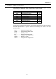
E6581281 f 3.7.3. Control Supervisor Object Common Services Service Code 0x05 0x0E 0x10 3.7.4. Supported Description of Service Class Instance N/A Yes Used to reset all resettable connection objects. N/A Yes Returns the contents of the specified attribute. N/A Yes Modifies the value of the specified attribute. Service Name Reset Get_Attribute_Single Set_Attribute_Single Control Supervisor Object Specific Services The Control Supervisor Object provides no object specific services. 3.7.5.
E6581281 f 3.8. AC/DC Drive Object Class code 0x2A. This object models the functions specific to an AC or DC Drive. e.g. speed ramp, torque control etc. 3.8.1.
E6581281 f 3.8.2.
E6581281 f 3.9. Vender Specific Device Profiles Class code 0x64. This object provides VF-AS1/PS1’s Parameter access. All parameter’s Attribute ID is 3. Refer to the following about each parameter’s Instance ID. Attribute ID of all parameters are 3. Moreover, about the instance ID of each parameter, it becomes "parameter communication number + 0x4000". In the case of the parameter from which a communication number begins in "F", it becomes "parameter communication number - 0x8000 (same as bit15 set to 0)".