XVS - DVS - HVS Digital Video Recorder User Manual model no. Please carefully read these instructions before using this product. Save this manual for future use.
ii
iii Surveillix™ XVS/DVS/HVS User Manual Manual Edition 29100AD – MAY 2009 Printed in USA No part of this documentation may be reproduced in any means, electronic or mechanical, for any purpose, except as expressed in the Software License Agreement. Toshiba shall not be liable for technical or editorial errors or omissions contained herein. The information in this document is subject to change without notice. THE INFORMATION IN THIS PUBLICATION IS PROVIDED “AS IS” WITHOUT WARRANTY OF ANY KIND.
iv
v LIMITED WARRANTY DIGITAL VIDEO RECORDER The Imaging Systems Division of Toshiba America Information Systems, Inc. (“ISD”) makes the following limited warranties. These limited warranties extend to the Original End-User (“You[r]”). Limited Two (2) Year Warranty of Labor and Parts The Imaging Systems Division of Toshiba America Information Systems warrants this product and parts against defects in material or workmanship for a period of two years from the date of original retail purchase by the end-user.
vi IMPORTANT SAFEGUARDS 1. Read Owner’s Manual – After unpacking this product, read the owner’s manual carefully, and follow all the operating and other instruction 2. Power Sources – This product should be operated only from the type of power source indicated on the label. If you are not sure of the type of power supply to your home or business, consult your product dealer or local power company 3.
vii IMPORTANT SAFEGUARDS, continued 16. Damage Requiring Service – Unplug the unit from the outlet and refer servicing to qualified service personnel under the following conditions: a. b. c. d. When the power-supply cord or plug is damaged. If liquid has been spilled, or objects have fallen into the unit. If the unit has been exposed to rain or water. If the unit does not operate normally by following the operating instructions.
viii NOTES ON CLEANING Use a soft dry cloth for cleaning. For stubborn dirt, soak the cloth in a weak detergent solution, wring well and wipe. Use a dry cloth to wipe it dry. Do not use any type of solvent, such as thinner and benzene, as they may damage the surface of the DVR. If using a chemical saturated cloth to clean the unit, follow that product’s instructions. NOTES ON MAINTENANCE This DVR is designed to last for long periods of time.
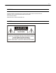
ix WARNING TO REDUCE THE RISK OF ELECTRICAL SHOCK, DO NOT EXPOSE THIS APPLIANCE TO RAIN OR MOISTURE. DANGEROUS HIGH VOLTAGES ARE PRESENT INSIDE THE ENCLOSURE. DO NOT OPEN THE CABINET. REFER SERVICING TO QUALIFIED PERSONNEL ONLY. CAUTION CAUTION RISK OF ELECTRIC SHOCK DO NOT OPEN CAUTION: TO REDUCE THE RISK OF ELECTRIC SHOCK, DO NOT REMOVE COVER (OR BACK). NO USER-SERVICEABLE PARTS INSIDE. REFER SERVICING TO QUALIFIED SERVICE PERSONNEL.
x RACK MOUNT INSTRUCTIONS Elevated Operating Ambient – If installed in a closed or multi-unit rack assembly, the operating ambient temperature of the rack environment may be greater than room ambient. Therefore, consideration should be given to installing the equipment in an environment compatible with the maximum ambient temperature (Tma) specified by the manufacturer.
xi CE NOTICE This product is in conformity with the following European Directives: ELECTROMAGNETIC COMPATIBILITY DIRECTIVE, 89/336/EEC (as amended by 92/31/EECand by Article 5 of 93/68/EEC) per the provisions of: EN55022:2006 EN61000-4-2:1995+A1+A2:2001 EN55024:1998+A1:2001+A2:2003 EN61000-4-3:1995+A1:2002 EN61000-4-8:1994+A1:2001 EN61000-3-2:2006 EN61000-4-4:1995+A1+A2:2004 EN61000-4-11:2004 EN61000-3-3:1995+A1:2001+A2:2005 EN61000-4-5:1995+A1:2001 LOW VOLTAGE DIRECTIVE, 73/23/EEC (as amended b
xii
xiii Table of Contents PREFACE ...................................................................................................................................................................... 1 ABOUT THIS GUIDE ................................................................................................................................................ 1 TECHNICIAN NOTES ..................................................................................................................................
xiv Connecting a PTZ Camera ................................................................................................................................. 24 Attaching the 3-Pin PTZ Adapter ................................................................................................................... 24 MAKING CONNECTIONS ON DVS / HVS.............................................................................................................. 25 Connecting a Video Source .............................
xv Create a Motion Area ......................................................................................................................................... 45 Activating an Alarm on a Motion Event ............................................................................................................... 46 Regular Interval Recording ................................................................................................................................. 46 FRAME SETUP OVERVIEW .............
xvi Add a New User ............................................................................................................................................. 67 User Rank ...................................................................................................................................................... 68 Changing the Administrator Password ............................................................................................................... 68 Default Administrator Password ..
xvii PAN / TILT / ZOOM OVERVIEW ............................................................................................................................ 88 SETTING UP A PTZ CAMERA ............................................................................................................................... 88 Enable the PTZ Settings ..................................................................................................................................... 88 Supported PTZ Protocols ............
xviii Installing Remote Software .......................................................................................................................... 113 Create a New Remote Connection .............................................................................................................. 113 Configuring the DVR .................................................................................................................................... 114 Configuring the Server for Remote Connection ....
xix
1 PREFACE ABOUT THIS GUIDE This manual is a setup and maintenance guide that can be used for reference when setting up the DVR and for troubleshooting when a problem occurs. Only authorized personnel should attempt to repair this unit. Toshiba reserves the right to make changes to the DVRs represented by this manual without notice.
2
3 INTRODUCTION PRODUCT DESCRIPTION A Surveillix XVS / DVS / HVS is a DVR, a server that performs as a High Definition Digital Recorder. By utilizing the many features of a computer, including processing power, storage capacity, graphics compression, and security features, the DVR is more powerful than the analog recorders of the past. The Surveillix DVR server software comes pre-configured for fast and seamless integration within your existing IT infrastructure.
4 FEATURES Toshiba’s Surveillix DVRs include the following new features: • Optimized and Designed for Microsoft® Windows XP Embedded® • Up to 32 Camera Inputs • Supports up to 16 Relay Outputs on Alarm Activation • Supports up to 16 Sensor Inputs for Alarm Control • Remote System Operation & Configuration • Supports Multiple Simultaneous Remote Connections • PAN / TILT / ZOOM Controls • Simultaneous Video Search, Playback and Backup • Video Indexes for Easy Searching • Multiple Levels of
5 CONTROLS AND CONNECTIONS This chapter includes the following information: • Input / Output Connector Locations • Front Panel Controls and LEDs • Rear Panel Connectors
6 FRONT PANEL CONTROLS The front panel of the DVR contains the devices that will be commonly used for data removal, retrieval, and backup replacement.
7 DVS / HVS DVD±RW Drive Hard Drive Activity & Power LEDs Hard Drive Array LOCK OPEN LOCK OPEN LOCK OPEN LOCK OPEN Cooling Fan Air Intake On / Off Power Switch USB Ports
8 REAR PANEL CONNECTORS The rear panel of the DVR contains the connectors used to attach cameras, sensors, and relays to the DVR.
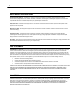
9 4 Channel BNC Connectors for Video Input RJ-45 Network Jack Audio/Spot Monitor Output AC Power Connector Cooling Fan 1394 DVI-D Sensors & Control Outputs PS/2 Mouse Input PS/2 Keyboard Input Audio USB Ports DVI-D Port SVGA Output Fire Wire RS-422 Interface • Line In – line level • Speaker Out • Microphone In – not used
10 DVS/HVS 8/16 Channel Control Alarm Outputs BNC Connectors for Video Input / Looping Output Sensor Inputs Looping Termination Switch CH 1 in CH 2 in CH 3 in CH 1 Out CH 2 Out CH 3 Out CH 4 in CH 5 in CH 6 in CH 7 in CH 8 in CH 9 in CH 10 in CH 11 in CH 12 in CH 13 in CH 14 in CH 15 in CH 16 in CH 4 Out CH 5 Out CH 6 Out CH 7 Out CH 8 Out CH 9 Ou t CH 10 Out CH 11 Out CH 12 Out CH 13 Out CH 14 Out CH 15 Out CH 16 Out ON OFF ON OFF CONTROL COM 1 2 3 4 5 6 7 8
11 32 Channel 16 CH Cable Adapters/Looping Outputs* Control Alarm Outputs BNC Connectors for Video Input Looping Termination Switch Sensor Inputs CH 1 in CH 2 in CH 3 in CH 17 in CH 18 in CH 19 in CH 4 in CH 5 in CH 6 in CH 7 in CH 8 in CH 9 in CH 10 in CH 11 in CH 12 in CH 13 in CH 14 in CH 15 in CH 20 in CH 21 in CH 22 in CH 23 in CH 24 in CH 25 in CH 26 in CH 27 in CH 28 in CH 29 in CH 30 in CH 31 in CH 16 in CH 32 in ON OFF BNC A ON OFF CONTROL COM SENSOR BNC B 1
12 PCI Card Configurations 120 PCI Configuration RCA Video Out Audio Inputs RS-485 Interface 240V PPS PCI Configuration RCA Video Out RS-485 Interface Audio Inputs 240 PPS 8/16 Channel PCI Configuration RCA Video Out RS-485 Interface Audio Inputs
13 240 PPS 32 Channel PCI Configuration RCA Video Out Audio Inputs RS-485 Interface 480 PPS 16 Channel PCI Configuration RCA Video Out S-Video Out SVGA Monitor Output RS-485 Interface Audio Input Cable Adapter 480 PPS 32 Channel PCI Configuration RCA Video Out S-Video Out RS-485 Interface SVGA Monitor Output Audio Inputs
14 NOTES:
15 GETTING STARTED This chapter includes the following information: • Included Components • Setting up the DVR Hardware • Optional Components
16 IDENTIFYING INCLUDED COMPONENTS Surveillix™ DVRs come with a mouse, keyboard and selected software and cables. Identify the following components to make sure everything has been properly included with the new DVR. If any of the following items are missing, contact the dealer to arrange a replacement.
17 OPTIONAL COMPONENTS To fully utilize the DVR’s potential; several optional Surveillix components are listed below. Contact the dealer for more information. 1 Extra Video Storage Hard Drive Each DVR has a virtually unlimited storage potential. Add additional Video Data Hard Drives to extend the amount of Video Data the DVR system can store before overwriting older data. 2 UPS UPS Power Backup UPS Power Backups allow your DVR to remain fully functional even in the event of a power failure.
18 KEYBOARD SETUP To attach the keyboard to the DVR, plug the end of the Keyboard into the keyboard PS/2 Port located on the back of the machine. The keyboard PS/2 Port can be identified by the purple color. Refer to the Rear Panel Connectors diagram for more information. MOUSE SETUP To attach the mouse to the DVR, plug the end of the mouse into the mouse PS/2 Port located on the back of the machine. The mouse PS/2 Port can be identified by the green color. The mouse uses a cursor called a pointer.
19 MONITOR SETUP The DVR has the following connections available to attach a monitor. SVGA Output To VGA Monitor. DVI-D Output To TV / Digital Monitor Attach the monitor or monitors to the rear of the DVR using the cable supplied by the monitor manufacturer. Refer to the monitor manual for detailed information on how to setup and use it.
20 MAKING CONNECTIONS ON AN XVS Connecting a Video Source There are different types of Video Sources that can be plugged into the XVS including DVD players, VHS players, and CCTV Cameras. The back of the XVS contains up to 16 video inputs depending on the model. The connectors use the BNC standard. 4 Channel Channel 1 Channel 2 Channel 3 Channel 4 16 Channel The video inputs are 75 Ώ BNC connectors. Plug one end into the video source (DVD, Camera, etc.
21 Connecting Sensors to the XVS Each XVS may have up to 16 Sensor inputs. These inputs can be used with devices such as infrared devices, motion device, glass breakage alarms, door and window trips, and many more. The Sensors can be set to Normally Open or Normally Closed inside the software. There are 4 Common Grounds (-) and 16 sensor inputs (+). There is no power supplied to the ports so an external power supply must be used if power is necessary.
22 Connecting Control Outputs to the XVS Each XVS may have up to 4 Control Outputs. These outputs can be used to trigger devices such as Sirens, Phone Dialers, Lights, and any other relay activated device. There is no power supplied to the ports. Use an external power supply if necessary. 16 Channel Siren, Alarm, Outside Relays (+) (-) External Power Supply (DC 12V) 4 Channel Siren, Alarm, Outside Relays (Common) External Power Supply (DC 12V) (Common) Use 12V, below 300mA.
23 Looping Outputs The 16 Channel XVS may have up to 16 Looping outputs. Depending on the destination of the outputs, each output may have to be terminated. The outputs are located on the BNC Connector Cable. Attach the cable to the input for the BNC Connector Cable highlighted below. The video inputs are 75 Ώ BNC connectors. Make sure there is a video source connected to the input and then connect a cable to the Channel Out on the BNC Connector Cable.
24 Connecting a PTZ Camera Setting up a PTZ Camera is simple. The DVR comes preassembled with an internal PTZ adapter. The cabling may be run up to 4,000 ft using 22 Gauge Twisted Pair. It is important to understand how the PTZ connects to the DVR. The DVR outputs an RS-232 signal and converts in to an RS-485 signal which is then sent to the PTZ camera. Attaching the 3-Pin PTZ Adapter 1. Locate the PTZ adapter cable. 2. Connect the two wires of the PTZ adapter to the PTZ camera.
25 MAKING CONNECTIONS ON DVS / HVS Connecting a Video Source There are different types of Video Sources that can be plugged into the DVR including DVD players, VHS players, and CCTV Cameras. The back of the DVR contains up to 32 video inputs depending on the DVR model. The connectors use the BNC standard.
26 Connecting Sensors to the DVS / HVS Each DVR has up to 16 Sensor inputs. These inputs can be used with devices such as infrared devices, motion device, glass breakage alarms, door and window trips, and many more. The Sensors can be set to Normally Open or Normally Closed inside the software. There are 4 Common Grounds (-) and 16 sensor inputs (+). There is no power supplied to the ports so an external power supply must be used if power is necessary.
27 Looping Outputs The 8/16 Channel DVS / HVS has up to 16 looping outputs. Depending on the destination of the looping outputs, each one may have to be terminated.
28 Looping Output Termination When it is necessary to terminate a looping output, the DVR has built in termination that allows users to select individual outputs. It is not always necessary to terminate the output; it depends on the device to which you are connecting. As a rule, if the image appears distorted or virtually unviewable, it likely needs to be terminated.
29 HARD DRIVE ARRAY (DVS / HVS ONLY) Button Lock Release Handle Handle Release Reset Button LOCK OPEN LOCK OPEN Power Buttons LOCK OPEN LOCK Temperature Alarm Light OPEN Swapping a Hard Drive 1. Press the Hard Drive Power Button to turn off power to the hard drive being removed. 2. Turn the Button Lock to the open position and push the Handle Release Button 3. Pull the Release Handle outward while removing the hard drive. Reverse steps to install.
30 TURNING ON THE DVR Once the cables and adapters have been properly connected it is time to turn on the power. To turn on the power follow these steps: 1. Turn on the monitor and any external peripherals (ex. Printers, External Storage Devices, etc.) connected to the DVR. 2. Turn on the Secondary Power Switch located in the rear of the DVR. 3. Turn on the main power switch located on the front of the DVR. The DVR will run a series of self-tests.
31 DVR BASICS This chapter includes the following information: • Turning the DVR on and off • Becoming familiar with the Display screen • Defining Screen Divisions
32 SETTING THE TIME AND DATE 1. Exit to Windows by clicking the Exit button from the Display screen and selecting Restart in Windows Mode. (See the Display screen section later in this chapter) 2. Open Windows Explorer. Do this by right-clicking the My Computer Icon (located on the top left hand corner of the Desktop) and select Explore. 3. Click on Control Panel to open it. If you do not see Control Panel listed, Click My Computer to expand the folder tree. 4.
33 Importing DVR Settings 1. Exit to Windows by clicking the Exit button on the Display screen and selecting Restart in Windows Mode. (See the Display screen section later in this chapter) 2. Click Start > Programs > Surveillix > VFormat. 3. Click the Import button in the System Settings Tool section. 4. Select the location of the settings file to import and click Open. 5. Click Yes to import the data file. 6. Click the OK button to close the VFormat Utility. Changing Video Format 1.
34 DISPLAY SCREEN Each time the DVR starts, the program defaults to the Display screen. The following diagram outlines the buttons and features used on the Display screen. You should become familiar with these options as this is the screen that will be displayed the majority of the time.
35 CAMERA VIEW Recording Status Special Recording Type INSTANT Camera No. and Name Recording Status Indicator The camera status for each camera is displayed in the upper right corner on the Video Display Area. The following are the different states for each camera: Recording Displayed when the camera is currently being recorded to the DVR. Motion Detection Displayed when a camera (set up for motion detection) detects motion.
36 SCREEN DIVISION BUTTONS The Screen Division menu allows you to view cameras in groups such as two by two, three by three and four by four. The button options are shown below. 1st Four Cameras View – Displays cameras 1-4 in the Video Display Area. To return to a different Multi-Camera View, select a different Screen Division option from the Screen Division menu. 2nd Four Cameras View – Displays cameras 5-8 in the Video Display Area.
37 SETUP OPTIONS This chapter includes the following information: • Setup Overview • Camera Setup • Motion • Frame Setup • Schedule • Sensor • Network • Information • Administrative
38 SETUP OVERVIEW The Setup options allow you to optimize your DVR by adjusting things like camera names, reboot schedules, recording schedules and more. It is extremely important that you setup your DVR correctly for several reasons. • Recording Schedules – By optimizing the recording schedule you can increase the amount of pertinent recorded video that is saved on the DVR and keep it longer.
39 CAMERA SETUP Define Camera Name Selected Camera Display Adjust • Brightness • Hue • Contrast Apply System Defaults to Selected Camera Apply Current Settings to all Cameras Apply System Defaults to All Cameras Set Up New Camera 1. Attach camera to the rear of the DVR chassis. 2. Click Setup on the Display screen. 3. Click Camera Setup to open the Camera Setup display. 4. Select the channel that corresponds with the new camera from the Select Camera list. 5.
40 NETWORK VIDEO Connected Devices Automatic Camera Finder Supported IP Camera Manufacturers ACTi Arecont Vision Axis Brans D-Link IQeye Lumenera Mobotix Panasonic Pixord Samsung Securgen Sony Stardot Toshiba VivoTek Connecting a Network Device Connecting Manually 1. From the Display screen, click Setup. 2. Click Network Video. 3. Click the Add/Remove Device tab. 4. Select your network device from the Device Type list. 5. Type a Device Name. 6.
41 Connecting with Camera Finder 1. From the Display screen, click Setup. 2. Click the Network Video tab. 3. Click the Add/Remove Device tab. 4. Click Find Cameras to automatically find all connected Network cameras. 5. Select the check box next to the desired camera. 6. Click Get Device. 7. Type the User ID and Password of the device. 8. Click Update. Assigning a Network Device to a Channel 1. From the Display screen, click Setup. 2. Click Network Video. 3.
42 Camera Configuration The Camera Configuration tab displays information on all cameras (analog and network) connected to the Surveillix DVR Displaying More Columns The Camera Configuration tab can be customized to display the information you use most. Click Select Column to add or remove specific columns.
43 HVR Upgrade and Registration Have the following information available before registering the HVR upgrade. HVR Software Serial Number: That product Serial Number is the unique number that Toshiba provided with the purchase software. System ID: The System ID is a number that is generated by the Surveillix unit. This is a unique code generated using the MAC address of the computer running the software. The following steps illustrate how to obtain a unique System ID. Locating the System ID 1.
44 5. Verify the information. 6. Click Next if the information provided is correct. 7. Once validated, the user will be provided with the Unlock Code. 8. Print the page and save for later reference. Unlocking the Upgrade 1. Return to Setup > Network Cameras > License. 2. Enter the Unlock Code generated by the Surveillix Registration Site into the License Key box. 3. Click Register and confirm that the new License Key is listed in the Channel Connection License box. 4. Click OK.
45 MOTION SETUP The DVR allows the user to adjust several different Motion Settings and create motion detection areas. Display full screen video pop up on motion event Beep on motion event Display full screen video pop up on sensor event Schedule recording at a regular specified interval Reduces Analog Signal Noise from Motion Detection Create a Motion Area 1. Click Motion in Setup. 2. Select a camera from the Select Camera list. 3. Select the Detect Detail Motion Area check box. 4. Click Clear.
46 Activating an Alarm on a Motion Event 1. In the Motion Setup window, select a camera to edit from the Camera list. 2. Create a motion area. 3. Select the Alarm Output check box. 4. Select a Control Output to activate for the selected camera. 5. Select an Alarm Duration time when a motion event occurs. Regular Interval Recording Regular Interval Recording allows users to record a single frame every few minutes or hours when there is no motion.
47 FRAME SETUP OVERVIEW The Frame Setup menu allows configuration of the PPS, resolution, quality, and sensitivity of camera channels. When configuring the PPS sliders the BLUE slider represents the PPS the DVR will record during intensive recording and have available for transmitting to remotely connected systems. The RED slider represents the PPS that will be recorded by the DVR under normal recording conditions. The total PPS of all blue sliders may not exceed the recording PPS of the DVR.
48 Frame Setup (Real Time Models) Video Format – NTSC/PAL Frame Status Box Reset Default Settings Select Camera Color (used in Frame Status Box) Sensitivity No. of Recording Frames Selected Video Quality Frame Select Recording Resolution Frame Select Blue Slider: Sets the PPS recorded during intensive recording and available for viewing on a remote client PC. Red Slider: Sets the PPS recorded by the DVR during normal recording.
49 Maximum PPS Table PPS Breakdown for Each Resolution Resolution CCTV x480 model x240 model 360x240 1CIF 480 PPS 240 PPS 720x240 * 2CIF 240 PPS 120 PPS 720x480 ** 4CIF 120 PPS 60 PPS Resolution CCTV x240V model x120 model 360x240 1CIF 240 PPS 120 PPS 720x240 * 2CIF 120 PPS 120 PPS 720x480 ** 4CIF 60 PPS 60 PPS * Frames recorded in 720x240 are twice the size of the standard 360x240.
50 SCHEDULE SETUP Recording Schedule The Recording Schedule window allows the user to create different recording schedules based on the day, time, and type of recording desired. In addition, this window contains the System Restart options that allow the user to perform basic system maintenance by automatically scheduling the DVR to restart periodically.
51 Sensor Schedule The Sensors will supersede all other types of recording modes (Motion and Continuous). Regardless of the recording schedule of a particular camera, if a sensor event occurs the associated cameras will begin recording as a Sensor Event. Sensor Recordings will be flagged and searchable using the Index Search Mode. Cameras are associated to sensors in the Camera Setup menu.
52 Create a Recording Schedule 1. Select a day to begin creating the schedule for -or- click Single Day Selection, enabling Multi Day Selection, to create the same schedule for multiple days. 2. Highlight the Time-Blocks within the Recording Schedule window for the camera(s) selected to schedule. Once the desired Time-Blocks are highlighted, click a Recording Mode button. The Time-Blocks should now appear Blue for Motion, Yellow for Continuous and White for No Recording.
53 Special Day Schedule The user can create days that have a unique recording schedule. If necessary create these on days that are ‘not typical’ such as Holidays, Special Events, etc. Special Day Mode / Normal Day Mode Date Bar Configured Special Days List Creating/Editing a ‘Special Day’ Schedule 1. Click Normal Day Mode to enable the Special Day Mode. 2. Select a day by typing the date or clicking the arrow to the right of the Date Bar. 3.
54 System Restart Setup System Restart Setup allows the user to define a schedule wherein the DVR automatically restarts according to specified parameters. Create System Restart Schedule 1. Click Schedule on the Setup screen. 2. Click Restart Setup. 3. Select the day(s) of the week to schedule an automatic system restart and select the check box to enable shut down. Note This step alone does not trigger the DVR to restart, only to shut down. 4.
55 SENSOR SETUP The Alarms setup window allows you to enable, disable and configure Sensors and Relays (Control Outputs). Associate Sensor w/ PTZ Presets Configure Hybrid (IP) Sensors* Open On-Screen Keyboard Normally Open (NO) / Normally Closed (NC) Delay Triggering Relay Output Assign Relay(s) comma delineated *Requires the HVR Software Upgrade Configure Sensor Response 1. Click Setup on the Display screen. 2. Click Sensor. 3.
56 Activate PTZ Preset on Sensor 1. Create a PTZ Preset Position. See instructions in the PTZ Setup chapter. 2. Click Setup on the Display screen. 3. Click Sensor. 4. Click Sensor Preset. 5. Select the desired camera from the Channel list. 6. Select the appropriate Sensor from the list. 7. Select the preconfigured PTZ Preset from the list. 8. Click Set. A list of configured Sensor Presets will display in the box below. 9. Repeat for additional sensors. 10.
57 GENERAL SETUP Enable Intensive Recording Adjust / Mute Volume Function Beep on Login Fail Enables the DVR to beep continuously in response to a failed login attempt. Only an authorized login will stop the beeping. Sequence Setting Allows the video out picture to automatically cycle through channels at a set speed. Example: .Cycle through channels 1-6 at four-second intervals. Display Options Use Full Screen Stretch the Surveillix interface to use the full monitor screen.
58 Intensive Recording Overview The Intensive Recording Option allows you to increase the Pictures Per Second of any camera, using sensor or motion activation. See Frame Setup for information on configuring intensive options. This guarantees that the Pictures Per Second and Resolution will be set correctly and not exceed the DVR limitation. Using Intensive Recording The Intensive Recording option is set up as ‘All or Nothing’.
59 TV-Out Setup (Multiplexer) The Multiplexer TV Out card is an optional upgrade that allows users to output video in a sequence or a matrix display. Note IP cameras will not display on the Multiplexer TV Out card. Configure Sequence Mode Tip If no cameras are configured in the TV Out Setup, the sequence mode will cycle through all connected camera. To configure settings for the TV Out sequence mode: 1. On the General screen of Setup, click TV Out Setup. 2.
60 Control Multiplexer Mode Display 1. Click TV Out on the Display screen. 2. Click Multiplexer. 3. To change the camera that is displayed on the monitor, click the desired camera number in the row that the monitor is connected to. Tip Port 1 is the top port on the TV Out card. Note Only Ports 1 and 2 can be configured in multiplexer mode. Channel 3 will mimic channel 1, and channel 4 will mimic channel 2. 4. Click the desired screen division to display in multiplex mode. 5.
61 Volume The volume control allows fine tuning of the volume settings on the DVR. Volume Options: • Slider Controls – Used to adjust the literal volume for the respective devices listed. • Mute Check Box – Select the mute check box to mute volume on any of the device columns or select the Mute All check box to mute all audio on the DVR. Audio The Surveillix DVR is capable of recording up to 16 channels of audio depending on the model.
62 Auto Sequence Setting Auto Sequencing is available either in the Display screen when Auto Sequencing has been enabled or when a Spot-Monitor out signal is used to display on a spot monitor. Auto Sequencing conveniently displays video channels at specified intervals and sequences through each selected channel.
63 NETWORK SETUP Network Setup allows the user to adjust settings such as Ports, setup emergency PPP information for use with the Emergency Agent and enable Remote Access. Settings for Video Sent to Remote Client Use with Emergency Agent Use with Remote Connections Enable RS-232 Keyboards (PTZ) Between DVR and Remote Client Transport Rate A bandwidth throttle based on percentage of free network. Web Viewer (iDVR) Enables/Disables access to the DVR using the Web Viewer interface.
64 PAN/TILT SETUP The Pan/Tilt Setup display allows enabling of PTZ cameras, creation of Presets, creation of Tours, and adjustment of camera speed settings. Some options listed here are features only available on selected cameras. Refer to the PTZ chapter in this manual for further information on setting up PTZ cameras and setting PTZ options.
65 ADMINISTRATIVE SETUP Select Date Log Data Display Export Log Data (1 to 7 days) Disk Management The Disk Management window is a native Windows function. This window displays the partition scheme and health status of the Hard Disk Drives in the DVR. This window is often used to troubleshoot a DVR, or verify the amount of Hard Drive storage installed. For more information about Disk Management, consult a Windows XP manual.
66 Setting Up DDNS Dynamic Domain Name System (DDNS) is a service that provides a static address to simplify remote connection to the DVR. This service is most useful for installations where the WAN (public) IP address is dynamic (changes from time to time). Most public IP addresses are dynamic unless a static address has been specifically ordered from the internet service provider. Enable DDNS To enable this functionality of the DVR, follow the steps below: 1.
67 User Management The User Management Console allows the administrator to create, edit, and delete user accounts. Each user account can be assigned different privileges to limit the usage of the DVR system. Users can be given administrator privileges by enabling all rights, however only the true administrator account can log into the User Management Console.
68 User Rank The User Ranking structure allows the option to assign a privilege system (1-10 where one has the most rights) to users of the DVR Software. For example. Since only one user is allowed to use the PTZ controls at any one time, an administrator with a higher rank can kick another user out and take control of the PTZ. The User Rank option affects: SETUP ACCESS - The DVR Software can only have 1 user accessing Setup at any given time.
69 Status Check / Email General 1. Click Setup on the Display screen. 2. Click Administrative. 3. Click Status Check/Email. 4. Select the Enable Email Alarm check box. 5. Enter a From Name and e-mail Address. Note This name and address will appear in the From line of the email alert message. 6. Enter the SMTP information for the “From” email account. Contact the email administrator for this information if necessary. 7.
70 Storage Check 1. Set up the General and Users tabs first. (see above) 2. Select the Use Storage Check check box. 3. Define the number of minutes. 4. Select an Alert Option, Beep or Popup Message, if desired. 5. Click Apply. Recording Data Check 1. Setup the General and Users tabs first. (see above) 2. Select the Recording Data Check check box. 3. Define the number of hours between data checks. 4. Select the Action Method. 5. Click Apply.
71 SMART Information The SMART Information tab displays Hard Drive information. SMART Alert 1. Setup the General and Users tabs first. (see above) 2. Select the Enable SMART Alarm. 3. Define the number hours between SMART checks. 4. Select the type of SMART event to trigger an action. 5. Define the maximum HDD temperature. 6. Select an action method. 7. Click Apply. Alarm Event 1. Setup the General and Users tabs first. (see above) 2. Select the Use Email Alarm check box. 3.
72 INSTANT RECORDING The Instant Recording feature allows users to manually initiate recording on a specific camera, overriding the current schedule. When Instant Recording is activated the DVR flags the clip as an event so Instant Recording instances can be found using the Index Search Instant Recording can be used, for example, when a suspicious object or person is detected and the user wants to flag that section of video for easy retrieval at a later date. Activate Instant Recording 1.
73 SEARCH This chapter includes the following information: • Setup Overview • Daylight SAVIng Time • Index Search • Preview Search • Graphic Search • Motion Search
74 SEARCH OVERVIEW The DVR has several options that allow the user to easily search through, and find, a particular section of video. From Motion/Sensor indexing to calendar views highlighting days with recorded video; the DVR is equipped to help the user quickly find a specific video or event. The following chapter describes how to use the DVR Search features.
75 Adjust the Brightness of an Image 1. Select an image to adjust by double-clicking on the desired image. Multiple images cannot be adjusted at one time. 2. Move the Brightness slide bar to the right or left to adjust the brightness. 3. Reset the Brightness by moving the slider back to the center of the bar. Zooming in on an Image 1. Select an image to adjust by double-clicking on the desired image. Multiple images cannot be adjusted at one time. 2.
76 PERFORMING A BASIC SEARCH There are several different types of searches that can be performed on the DVR. The most basic involves selecting the date, time, camera, and clicking play. 1. Click the Calendar button to select a date. 2. Select a time by clicking the up and down arrows to the right of the time display. 3. Click OK. 4. Select one or more cameras. 5. Click Play. Video can be played forwards, backwards, or frame-by-frame. PRINTING AN IMAGE 1.
77 SAVE TO JPG OR AVI The DVR can export single images in a JPG Image file format and save video clips in an AVI format. Both JPG and AVI file formats are the most commonly used graphical formats today. Virtually every computer offers some type of support for these file formats which make them the most ideal formats to use. JPG Optimized for compressing full-color or grayscale photographic images, JPG images are 24-bit (16.7 million color) graphics. Use JPG to export a single image or frame.
78 Bookmarks Use bookmarks to mark a video clip during a search. Export bookmarked data using the Clip Backup feature. 1. Perform a search for the desired video. 2. Stop playback at the beginning of the desired clip. 3. Right-click the video and select Start Bookmark. 4. Click the play button to continue playback. 5. Stop playback at the end of the desired clip. 6. Right-click the video at the desired end point and select End Bookmark. 7. Type a name to identify the bookmark in the Title box.
79 Single Clip Backup Along with the Save option, a single camera backup option is also included with the Surveillix software. The single Camera or Clip Backup allows the user to backup a single camera without hAVIng to backup multiple cameras at a given time. The Clip Backup option gives the users the ability to choose a backup time frame, choose a specific camera, add memos, and even make a copy for the Backup Viewer if needed. 1. From the Search screen, click Save. 2.
80 INDEX SEARCH Using the Index Search can greatly decrease the amount of time spent searching through saved video. The Index Search allows a user to perform a search based on criteria such as Sensor, Motion and Instant Record events Performing an Index Search 1. Click the Calendar button on the Search screen to select the date to search. 2. Click Index Search. 3. Select the cameras and sensors to include in the search. 4. Select the Select Time check box to define a specific period. 5.
81 PREVIEW SEARCH Preview Search can be used in a number of circumstances to quickly find an exact moment where an event, such as a theft, occurred. The Preview Search gives a 24 Hour visual overview of a single camera by separating a 24 hour period (1 day) into 24 images, one image for each hour of the day. The search can then be further narrowed down into ten minute increments and one minute increments by selecting one of the images displayed. These example images show how the Preview Search functions.
82 Performing a Preview Search 1. Select a single camera by either turning off all cameras but one or double-clicking a displayed image. 2. Click Preview Search. 24 images display. If there is no recorded video during a portion of the day, “No Image” will be displayed where the image should be. 3. Refine the search by double-clicking on an image to select it. 6 images display. If needed, return to the previous 24-image view by right-clicking on an image. 4.
83 OBJECT SEARCH Object Search is a powerful search utility that is used to search a region on the video for any motion changes. Results are neatly displayed and can be viewed quickly. Performing an Object Search 1. Perform a Basic Search. See the instructions on Performing a Basic Search. 2. Select a single camera, either by turning off all cameras but one or by double-clicking a displayed image. 3. Click Object Search on the Search screen. 4.
84 MOTION SEARCH The Motion Search provides a dynamic display of the levels of motion in recorded video. Adjust the level of motion to only play clips of video at or above that level. Tip To enable motion data to be saved for Motion search, ensure that you select the following settings: On the Motion setup page under Motion Regions, select the Detect Detail Motion Area check box. On the General setup page under Display, select the Motion Detect on Continuous Recording check box.
85 SEARCH IN LIVE The Search in Live feature allows users to review events immediately while monitoring live video. Pause, rewind, and resume live video within seconds of an alarm event or suspicious activity. 1. Move the mouse cursor over the desired live video display on the Live Display screen. 2. Press the scroll button on the mouse. 3. The search in live Controls will display at the bottom of the image. 4. Use the controls to pause, rewind, move frame-by-frame or resume playing as desired.
86 NOTES:
87 PAN / TILT / ZOOM This chapter includes the following information: • Overview • Setting up the PTZ • Creating and Viewing a Preset Position • Creating and Viewing a Preset Pattern
88 PAN / TILT / ZOOM OVERVIEW The PTZ controls within the DVR allow for powerful control over the cameras. This can be extremely beneficial by increasing the usefulness of the recorded video. Using the PTZ controls you can create custom preset configurations that can continuously sweep across large areas. SETTING UP A PTZ CAMERA Setting up a PTZ Camera is simple. The DVR comes preassembled with an internal PTZ adapter. The cabling may be run up to 4,000 ft using 22 Gauge Twisted Pair.
89 Supported PTZ Protocols Protocols are added frequently. The supported list may contain new protocols that are not listed here.
90 ADVANCED PTZ SETUP PTZ signal type Adjust Speed Settings Connection Settings Note Preset and Tour options may vary depending on the camera Creating and Viewing Preset Positions A Preset Position is a user-defined location where the camera can be pointed, zoomed in, and focused. Preset positions can be defined and labeled if the camera supports this. Creating a Preset 1. Inside Setup, click PTZ and select the camera. 2. If the camera is already selected click Open PTZ Controller. 3.
91 PTZ Address Settings Some protocols support software address settings. The RX Addresses and ID settings are compatible with a particular line of receivers that support 2 ID addresses. The PT Driver Address is associated with the PTZ ID address set on the camera. The addresses must match for the DVR to communicate with the proper PTZ camera. This is especially important when a large number of PTZ cameras are connected to the DVR.
92 CONTROLLING A PTZ CAMERA The Surveillix DVRs provide control for a PAN/TILT/ZOOM camera in two different ways. The first method is to use the Graphical PTZ Controller that appears when the PTZ button is clicked on the Display screen. The second method is to use the mouse to control the camera directly from the live video display. (On-Screen Compass) Using the Graphical PTZ Controller 1. Use the Arrow buttons to control the direction of the PTZ camera. 2.
93 Using the On-Screen Compass 1. Click Setup on the Display screen. 2. Click PTZ. 3. Select the On Screen Compass check box to enable the feature. 4. Click Apply. 5. Click Exit to return to the Display screen. 6. Click PTZ. 7. Control the PTZ by dragging the mouse on the screen in the desired direction. Note A green line will appear to show the direction the PTZ will move. The shorter the line the less the PTZ will move.
94 PTZ Tour Schedule Hours 0-23 (24 hours) Cameras Create PTZ Tour Schedule 1. Click Setup on the Display screen. 2. Click PTZ. 3. Click Tour Schedule to open the PTZ Tour Schedule window. 4. In Single Select Mode select one day of the week to create a schedule for or toggle to Multi Select Mode to select multiple days with the same schedule. 5. Click and drag the mouse cursor to select blocks of time (hours 0-24) and corresponding cameras. 6. Click Select. 7.
95 BACKING UP VIDEO DATA This chapter includes the following information: • Overview • Saving Video to a DVD • Saving Video from a Single Camera • Scheduling Regular Video Backup
96 BACKUP OVERVIEW The Backup Center allows you to back up recorded video data from multiple dates and times to one or more locations including the DVD-RW drive, Network Storage Locations, and External Hard Drives. The DVR can easily backup important video data to an internal or external media location. The most commonly used forms of this are CD-R/RWs, External USB or FireWire Hard Drives, and Network Drives. Every DVR comes equipped with a DVD-RW drive, USB port, and Network Adapter.
97 General Screen Overview The General Backup Screen is used for performing bulk backup of video recorded by all cameras for a selected period, or periods, to a specified storage location. Calendar Select Additional Drive/Folder Define Drive Priority Select Remote Network Location Hour / Minutes Recording data displays in hourly (24 horizontal columns) and 10-minute (6 vertical cells) segments. Green cells indicate time with recorded video. Red cells indicate time selected for backup.
98 Clip Screen Overview The Clip Screen is used for backing up video recorded by individual cameras for a selected period of time to a specified storage location Performing a Clip Backup 1. Click Backup on the Display screen. 2. Click the Clip tab at the top of the Backup Center window. 3. Set the Start Time and End Time under Time Setup. 4. Select the cameras to back up in the Channel Selection box. 5. Select the Backup Drive to save the backup video to. 6.
99 Scheduled Screen Overview The Scheduled Backup Screen is used for performing bulk backup of video recorded by all cameras for a selected period, on a regular scheduled basis (1-24 hours). The Scheduled Backup Screen is similar to the General Backup Screen. Performing a Scheduled Backup 1. Click Backup on the Display screen. 2. Click the Schedule tab at the top of the Backup Center window. 3. Select the blocks of time to back up using the Hour/Minute Grid.
100 NOTES:
101 LAN / ISDN / PSTN CONNECTIONS This chapter includes the following information: • Overview • Configuring TCP/IP Settings • Connecting to a LAN • LAN / ISDN / PSTN Connections
102 LAN OVERVIEW The DVR can be easily connected to a Local Area Network (LAN) and uses Microsoft’s® powerful and secure Windows® XP Embedded operating system. This allows for easy and well-documented instructions on setting up LAN connections no matter what type of LAN you want to use. A LAN is a group of computers and other devices dispersed over a relatively limited area and connected by a communications link that allows one device to interact with any other on the network.
103 WEB VIEWER This chapter includes the following information: • Overview • Configuring the Web Viewer
104 WEB VIEWER OVERVIEW The DVR allows you to access video using Microsoft® Internet Explorer® 7. Highlights: View Live Video from most computers Username and Password protected Easy to use graphical interface Basics: 75 users can access the Web DVR simultaneously. The Web Viewer is an easy, secure way to view live video from virtually any computer with an internet connection using Microsoft Internet Explorer. In order to log in to the DVR server, a user account must be made for the user.
105 Configuring the Server for Remote Connection 1. Click Setup on the main display screen. 2. Click Network. 3. Clear the Disable Remote Control check box. You should now be allowed to adjust port settings if necessary. NOTE: If you are using a Firewall, it may be necessary to adjust the port settings on both the DVR and the Firewall. Contact the Network Administrator for more information. 4. Select the Web Viewer (iDVR) check box. 5. Click Apply. 6. Make sure a User account is created.
106
107 INCLUDED SOFTWARE SETUP This chapter includes the following information: • Emergency Agent Overview • Remote Software Overview • Digital Verifier • Backup Viewer • SCS Multi Site Software Overview
108 EMERGENCY AGENT OVERVIEW The Emergency Agent software is a utility that streams video across a Local Area Network to a Client PC when an alarm is detected on the DVR. The video that streams across can be stopped, played forwards and backwards, in slow motion or real speed. The utility is loaded at startup and placed in the taskbar. It constantly monitors for a signal from the DVR.
109 Setup Window Network Port Indicates the port which the Emergency Agent uses to listen for incoming events. This number should be changed to the same number as is set in the Emergency Port in Network Settings on the DVR. Save Directory Sets the location that recorded video footage is saved to. Notice Options Configuration settings for activating an audible indicator or popup window when the Emergency Agent receives an event.
110 Add Items to Alarm Confirm List 1. From the Option menu, click Setup. 2. Type the desired text in the box below the Alarm Confirmation List. NOTE: The items in the Alarm Confirmation List will be available on a list under Status Setting in main Emergency Agent screen. 3. Click Add. 4. Click OK to save changes and close the window.
111 SEARCH ALARM WINDOW Video Display Play Controls Go to Next Event Go to Previous Event Alarm Event Information Export Quality It may be necessary to reduce the overall size of an AVI file; for example, to email to someone. AVI file sizes can be reduced by reducing the image quality. However, reducing the image quality causes the AVI video to appear more pixilated. When size is not an issue, setting quality to 100 is highly recommended.
112 REMOTE SOFTWARE OVERVIEW The DVR was specifically designed to be fully operated and maintained remotely. It connects using the standard TCP/IP protocol thorough connection types such as DSL, Cable Mode, T1, ISDN, 56K Modem, LAN, and more. The Surveillix Remote software allows you to view live video, search through archived video, export images and video clips and have virtually full Setup control. Surveillix Remote Software is Microsoft Vista® compatible.
113 Remote Software Setup Installing Remote Software 1. On the client computer, insert the Surveillix Software CD into the CD-ROM. The CD should play automatically. 2. When prompted, select the Install Remote Software option. Follow the installation instructions carefully. 3. When the software finishes installing, close any open installation windows. Create a New Remote Connection DVR Site List Import/Export saved configurations Selected Site Information 1.
114 Configuring the DVR In order to access the DVR remotely, the DVR Server must be setup to allow remote connections. Time Out Value Specifies a value (in seconds) to wait for a signal from the Surveillix Remote Client. If a signal is not received by that time, the connection is dropped. Center Port Used to transfer the connection data. Image Port Used to transfer the image data. Search Port Used to transfer the search data. Configuring the Server for Remote Connection 1. Enter Setup on the DVR.
115 DIGITAL VERIFIER OVERVIEW JPG images and AVI video files that are exported from the Digital Video Recorder are automatically embedded with a digital signature. Digital Signatures are a way to verify the authenticity of the images to ensure that they have not been tampered with or edited in any way. Included on the Software Installation DVD supplied with the DVR is the Digital Signature Verification program. This program can be installed on any computer and loads an image in question.
116 BACKUP VIEWER OVERVIEW The Backup Viewer allows you to play back the exported video in its proprietary format. Video saved in this format is extremely difficult to tamper with and therefore is the ideal solution when law enforcement and the legal department are involved. This video cannot be read by any other viewer. The Backup Viewer operates essentially like the Search portion of the DVR software. For detailed explanations of these functions, refer to the chapter on Search Options in this manual.
117 SCS OVERVIEW SCS software is Network DVR Management Software; a powerful utility that allows 100 or more DVRs to be controlled using one computer. This software allows you to view live video, search saved video, edit and configure setup on each DVR, and import maps of buildings and other locations. The SCS software was specifically designed as an Enterprise software solution.
118 NOTES:
119 APPENDIX: SPECIFICATIONS XVS SPECIFICATIONS 4 (120 PPS) CPU 16 (240V PPS) 16 (240 PPS) Intel® CPU Storage (Hard Drive) 500 GB Standard / 2 TB Maximum Storage MAX Up to 2 HDD with DVD±RW RAM 1 GB Operating System Microsoft® Windows® XP Embedded NTSC 120 PPS 240 PPS 480 PPS PAL 100 PPS 200 PPS 400 PPS Digital Control Output 4 4 4 Sensor Input 4 16 16 NTSC 120 PPS 360x240 120 PPS 720x240 60 PPS 720x480 240 PPS 360x240 120 PPS 720x240 60 PPS 720x480 240 PPS 360x240 120 PPS 720
120 DVS/HVS SPECIFICATIONS 8 16 CPU Intel® CPU Storage (Hard Drive) 500 GB Standard / Virtually Unlimited Storage Potential Storage MAX Up to 4 HDD with DVD±RW RAM 1 GB Operating System Viewing Rate Recording Rate 32 Microsoft® Windows® XP Embedded NTSC Max 480 FPS PAL Max 480 FPS NTSC 240 PPS – Max 240 FPS / 480 PPS – Max 480 PPS PAL 240 PPS – Max 200 FPS / 480 PPS – Max 400 PPS Digital Control Output 8 16 16 Sensor Input 8 16 16 Resolution NTSC 720x480 / 720x240 / 360x240