MULTIFUNCTIONAL DIGITAL COLOR SYSTEMS / MULTIFUNCTIONAL DIGITAL SYSTEMS MFP Management Guide
©2011, 2012 TOSHIBA TEC CORPORATION All rights reserved Under the copyright laws, this manual cannot be reproduced in any form without prior written permission of TTEC.
Preface Thank you for purchasing TOSHIBA Multifunctional Digital Systems or Multifunctional Digital Color Systems. This manual explains the instructions for administrators to set up and manage the Multifunctional Digital Systems or Multifunctional Digital Color Systems. Read this manual before using your Multifunctional Digital Systems or Multifunctional Digital Color Systems. Keep this manual within easy reach, and use it to configure an environment that makes the best use of the e-STUDIO’s functions.
Trademarks y y y y y y y y y y y y y 2 The official name of Windows XP is Microsoft Windows XP Operating System. The official name of Windows Vista is Microsoft Windows Vista Operating System. The official name of Windows 7 is Microsoft Windows 7 Operating System. The official name of Windows Server 2003 is Microsoft Windows Server 2003 Operating System. The official name of Windows Server 2008 is Microsoft Windows Server 2008 Operating System.
CONTENTS Preface....................................................................................................................................... 1 Chapter 1 SETTING ITEMS (USER) Entering User Menu.................................................................................................................. 8 Setting General Functions....................................................................................................... 9 Changing the display language .............................
Setting the TCP/IP protocol (IPv4) .................................................................................... 134 Setting the IPv6 protocol ................................................................................................... 139 Setting the IPX/SPX protocol............................................................................................. 148 Setting the NetWare settings.............................................................................................
Chapter 4 APPENDIX List Print Format................................................................................................................... 246 TOTAL COUNTER LIST.................................................................................................... 246 DEPARTMENT CODE LIST.............................................................................................. 247 ADDRESS BOOK INFORMATION....................................................................................
6 CONTENTS
SETTING ITEMS (USER) 1. Entering User Menu ................................................................................................................. 8 Setting General Functions....................................................................................................... 9 Changing the display language ..............................................................................................................................9 Setting the reversed display mode ............................
1 SETTING ITEMS (USER) Entering User Menu Follow the steps below to enter the USER menu in the USER FUNCTIONS screen. 1 Press the [USER FUNCTIONS] button on the control panel to enter the USER FUNCTIONS menu. 2 Press the [USER] tab. 3 Continue the user setting operation that you require. The USER menu is displayed. For e-STUDIO6550C Series, e-STUDIO4540C Series For e-STUDIO456 Series, e-STUDIO856 Series P.9 “Setting General Functions” P.16 “Setting Copy Functions” P.22 “Setting Fax Functions” P.
1 SETTING ITEMS (USER) Setting General Functions This menu allows you to perform the following operations: y P.9 “Changing the display language” y P.10 “Setting the reversed display mode” y P.12 “Adjusting the display contrast” y P.13 “Setting the calibrations” y P.15 “Setting the registration” Changing the display language The language used on the touch panel can be changed to a different one. 1 Press [GENERAL] in the USER menu. The GENERAL menu is displayed.
1 SETTING ITEMS (USER) Setting the reversed display mode You can change the touch panel to be displayed in the Reversed Display mode in which the white portion is black and the black portion is white. Changing to the Reversed Display mode helps to display the touch panel more clearly when it is too bright. 1 Press [GENERAL] in the USER menu. The GENERAL menu is displayed. To display the USER menu, see the following page: P.8 “Entering User Menu” 2 Press [REVERSED DISPLAY].
1 SETTING ITEMS (USER) 1.SETTING ITEMS (USER) 3 Press [ON] to enable the reversed display, or [OFF] to disable the reversed display. When you select [ON], the touch panel is displayed in the Reversed Display mode.
1 SETTING ITEMS (USER) Adjusting the display contrast This function allows you to adjust the touch panel contrast. 1 Press [GENERAL] in the USER menu. The GENERAL menu is displayed. To display the USER menu, see the following page: P.8 “Entering User Menu” 2 Press [DISPLAY SETTING]. The DISPLAY SETTING menu is displayed. 3 Adjust the touch panel contrast. Use to brighten the touch panel display. Use to darken the touch panel display.
1 SETTING ITEMS (USER) 1.SETTING ITEMS (USER) Setting the calibrations This function automatically calibrates the color gradation of the machine.
1 SETTING ITEMS (USER) 3 Press [CALIBRATION]. The CALIBRATION menu is displayed. 4 Refer to Step 1 in the following operations. To perform copy calibration, see the following page: P.95 “Setting the copy calibration” To perform print calibration, see the following page: P.97 “Setting the print calibration” Instructions on how to perform copy and print calibrations are the same when they are performed in the ADMIN menu.
1 SETTING ITEMS (USER) 1.SETTING ITEMS (USER) Setting the registration When color misregistration occurs, this function allows you to align the position of each color. This option is available only for the e-STUDIO6550C Series and e-STUDIO4540C Series. The registration setting in the USER menu can be configured only when an administrator has set the Registration Display Level to [USER]. P.93 “Setting the calibration and registration display level” 1 Press [GENERAL] in the USER menu.
1 SETTING ITEMS (USER) Setting Copy Functions You can change the initial settings (defaults) for copy jobs. 1 Press [COPY] in the USER menu. The COPY screen is displayed. y When you are using the e-STUDIO6550C Series or e-STUDIO4540C Series, see the following page: P.16 “Setting Copy Functions (e-STUDIO6550C Series, e-STUDIO4540C Series)” y When you are using the e-STUDIO456 Series or e-STUDIO856 Series, see the following page: P.
1 SETTING ITEMS (USER) 1.SETTING ITEMS (USER) 2 Press the desired media type button and press . For the e-STUDIO4540C Series For the e-STUDIO6550C Series For more information about the paper types, refer to the Copying Guide “Chapter 1: BEFORE USING EQUIPMENT”. 3 Press the desired mode button for the ORIGINAL MODE FOR COLOR and ORIGINAL MODE FOR BLACK options and press .
1 SETTING ITEMS (USER) 4 Specify the following items as required and press [OK]. ORIGINAL MODE FOR AUTO COLOR — Press the desired mode button that is applied when you copy documents in the Auto Color mode. OMIT BLANK PAGE ADJUSTMENT — Use and to select the appropriate sensitivity from 7 levels to detect blank pages from the scanned data in a copy job. The higher the level is, the more likely the equipment is to detect blank pages.
1 SETTING ITEMS (USER) 1.SETTING ITEMS (USER) 2 Press the desired media type button and press . For e-STUDIO456 Series For e-STUDIO856 Series For more information about the paper type, refer to the Copying Guide “Chapter 1: BEFORE USING EQUIPMENT”.
1 SETTING ITEMS (USER) 3 Specify the following items as you require. For e-STUDIO456 Series ORIGINAL MODE — Press the desired mode button. OMIT BLANK PAGE ADJUSTMENT — Use and to select the appropriate sensitivity from 7 levels to detect blank pages from the scanned data in a copy job. The higher the level is, the more likely the equipment is to detect blank pages. For more information about the omit blank page function, refer to the Copying Guide “Chapter 4: EDITING FUNCTIONS”.
1 SETTING ITEMS (USER) 1.SETTING ITEMS (USER) 4 Specify the following item as you require and press [OK]. For e-STUDIO856 Series TAB EXTENSION — This option allows you to set the tab extension of the tab paper that are set in the drawers or Bypass Feed Tray. This option also allows you to specify the shift margin for moving the copy image to the desired position on the tab extension. The default settings are changed as specified.
1 SETTING ITEMS (USER) Setting Fax Functions You can change the initial settings (defaults) for fax and Internet Fax jobs. If the FAX Unit (optional) is not installed, only five options are available: “RESOLUTION”, “ORIGINAL MODE”, “EXPOSURE”, “PREVIEW SETTING” and “INITIAL PREVIEW TYPE”. For details on other fax options, refer to the GD-1250/GD-1260/GD-1270 Operator’s Manual for FAX Unit “Chapter 6: SETTING ITEMS”.
1 SETTING ITEMS (USER) 1.SETTING ITEMS (USER) 3 Specify the following items as required and press [OK]. PREVIEW SETTING — Press [ON] to enable the Preview function to preview the scans before you send them via fax or Internet Fax. Press [OFF] to disable it. INITIAL PREVIEW TYPE — Select [PAGE FIT] or [WIDTH FIT] for the preview screen. [PREVIEW SETTING] and [INITIAL PREVIEW TYPE] are available only for the e-STUDIO6550C Series and eSTUDIO4540C Series. The default settings are changed as specified.
1 SETTING ITEMS (USER) Setting Scan Functions You can change the initial settings (defaults) for scan jobs. For the e-STUDIO456 Series or e-STUDIO856 Series, [SCAN] in the USER menu is available only when the Scanner Kit (optional) or Printer/Scanner Kit (optional) is installed. 1 Press [SCAN] in the USER menu. The SCAN screen is displayed. To display the USER menu, see the following page: P.8 “Entering User Menu” 2 Specify the following items as required and press .
1 SETTING ITEMS (USER) 1.SETTING ITEMS (USER) 3 Specify the following items as required and press . PREVIEW SETTING — Press [ON] to enable the Preview function to preview the scans before you save or e-mail them. Press [OFF] to disable it. INITIAL PREVIEW TYPE — Select [PAGE FIT] or [WIDTH FIT] for the preview screen. OMIT BLANK PAGE ADJUSTMENT — Use and to select the appropriate sensitivity from 7 levels to detect blank pages from the scanned data in a scan job.
1 SETTING ITEMS (USER) 5 Specify the following items as required and press . RESOLUTION — Select the corresponding button for the default resolution applied when scanning in the Gray Scale mode. EXPOSURE — Press the or button to specify the default exposure for gray scale scans manually, or press [AUTO] to select the Auto mode as the default exposure mode for gray scale scans. BACKGROUND ADJUSTMENT — Press the or button to specify the contrast for gray scale scans.
1 SETTING ITEMS (USER) Setting e-Filing Functions You can set the image quality type for printing color documents that have been stored by Scan to e-Filing. This option is available only for the e-STUDIO6550C Series and e-STUDIO4540C Series. 1 Press [E-FILING] in the USER menu. The E-FILING screen is displayed. To display the USER menu, see the following page: P.8 “Entering User Menu” 2 In the Printing Image Mode option, press the desired mode button and press [OK].
1 SETTING ITEMS (USER) Printing Lists This function allows you to print the following lists. y ADDRESS BOOK INFORMATION You can print ADDRESS BOOK INFORMATION that shows all registered contacts in the equipment. y GROUP NUMBER INFORMATION You can print GROUP NUMBER INFORMATION that shows all registered groups and members in the equipment. y FUNCTION LIST (User) You can print FUNCTION LIST that shows the function flow under [USER] of the user functions.
1 SETTING ITEMS (USER) 1.SETTING ITEMS (USER) Printing ADDRESS BOOK INFORMATION 1 Press [ADDRESS BOOK]. The ADDRESS BOOK menu is displayed. 2 Press [ID SORT] to print it as sorted by the ID number, or [NAME SORT] to print it as sorted by the last name. y When the Department Management feature is disabled, ADDRESS BOOK INFORMATION is printed. y When the Department Management feature is enabled, the screen to input the department code is displayed.
1 SETTING ITEMS (USER) Printing GROUP NUMBER INFORMATION 1 Press [GROUP NUMBERS]. y When the Department Management feature is disabled, GROUP NUMBER INFORMATION is printed. y When the Department Management feature is enabled, the screen to input the department code is displayed. Enter the department code using the on-screen keyboard and press [OK] to print GROUP NUMBER INFORMATION. However, when the No Limit Black function ( P.
1 SETTING ITEMS (USER) Setting Drawer This function allows you to set the paper size and paper type for each drawer. 1 Press [DRAWER] in the USER menu. The DRAWER screen is displayed. To display the USER menu, see the following page: P.8 “Entering User Menu” 2 Press the drawer portion in the illustration to highlight the drawer whose paper size you want to change, and press the desired paper size button.
1 SETTING ITEMS (USER) For the e-STUDIO6550C Series y The selected paper size is displayed in the drawer in the illustration. y If you want to change the paper type from plain paper to another or want to specify the purpose of use of the paper in the drawer, press [PAPER TYPE] and proceed to step 3. y Selecting [AUTO (mm)] or [AUTO (inch)] allows the equipment to automatically detect the size of paper in the drawer. To set A/B format paper such as A3 and A4, press [AUTO (mm)].
1 SETTING ITEMS (USER) 1.SETTING ITEMS (USER) 3 Press the drawer portion in the illustration to highlight the drawer whose paper type you want to change, and press the desired paper type button, and then press [OK] to save the settings. For the e-STUDIO4540C Series You can select either [RECYCLED PAPER], [THICK1], [THICK2], or [THICK3] for the paper type. For the e-STUDIO6550C Series You can select either [PLAIN 1], [PLAIN 2], [RECYCLED PAPER], [THICK1], [THICK2], or [THICK3] for the paper type.
1 SETTING ITEMS (USER) For e-STUDIO856 Series You can select either [THICK1], [THICK2], or [THICK3] for the paper type. y For details of the paper types, refer to the Copying Guide “Chapter 1: BEFORE USING EQUIPMENT”. y You can select each button of the attribute to restrict the uses for a specific job. For example, if you select [INSERT] for a drawer, the paper in the drawer is always used for copy insertion.
1 SETTING ITEMS (USER) Managing Address Book This menu allows you to perform the following operations: y P.35 “Managing contacts in address book” y P.50 “Managing groups in address book” Managing contacts in address book The address book is made accessible by pressing [ADDRESS BOOK]. Entries in the address book are used to specify e-mail addresses and/or fax numbers for fax transmission and Scan to E-mail.
1 SETTING ITEMS (USER) 2 Press the [SINGLE] tab. 3 Press an undefined button to create a new contact and press [ENTRY]. The ADDRESS BOOK REGISTRATION screen is displayed. If the touch panel does not display an undefined contact, press 36 Managing Address Book to display the next screen.
1 SETTING ITEMS (USER) 1.SETTING ITEMS (USER) 4 Press each button on the touch panel to enter the following contact information. [FIRST NAME] — Press this button to enter the first name of the contact. This name will appear in the address book list on the touch panel. [LAST NAME] — Press this button to enter the last name of the contact. This name will appear in the address book list on the touch panel. [FAX NO.] — Press this button to enter the fax number of the contact.
1 SETTING ITEMS (USER) y When you press each button (excluding [FAX NO.] and [2ND FAX]), the on-screen keyboard is displayed. Enter the value using the on-screen keyboard and press [OK] to set the entry. You can also use the digital keys on the control panel to enter numerals. y When you press [FAX NO.] and [2ND FAX], the following on-screen keyboard for entering the fax number will be displayed. Press [Pause] to enter “-” in [FAX NO.] and [2ND FAX].
1 SETTING ITEMS (USER) 1.SETTING ITEMS (USER) Registering contacts from Log lists You can register information such as remote fax numbers and e-mail addresses in the address book from the Send/ Receive Log screen.
1 SETTING ITEMS (USER) 4 Enter the contact information. For the description of each item, see step 4 in the following operation: P.35 “Registering contacts from the [USER FUNCTIONS] button” 5 Press [OPTION] to specify the default settings for a fax transmission. y This is available only when the FAX Unit (optional) is installed. y For details of the settings, refer to the GD-1250/GD-1260/GD-1270 Operator’s Manual for FAX Unit “Chapter 6: SETTING ITEMS”. 6 Press [OK] to register the contact.
1 SETTING ITEMS (USER) 1.SETTING ITEMS (USER) Editing contacts You can edit existing contacts in the address book. 1 Press [ADDRESS] in the USER menu. The ADDRESS BOOK screen is displayed. To display the USER menu, see the following page: P.8 “Entering User Menu” 2 Press the [SINGLE] tab. 3 Press the contact that you want to edit and press [EDIT]. The ADDRESS BOOK EDIT screen is displayed. y If the touch panel does not display the contact that you want to edit, press to display the next screen.
1 SETTING ITEMS (USER) 4 Press each button on the touch panel to edit the contact information. For the description of each item, see step 4 in the following operation: P.35 “Registering contacts from the [USER FUNCTIONS] button” 5 Press [OPTION] to specify the default settings for a fax transmission. y This is available only when the FAX Unit (optional) is installed. y For details on the settings, refer to the GD-1250/GD-1260/GD-1270 Operator’s Manual for FAX Unit “Chapter 6: SETTING ITEMS”.
1 SETTING ITEMS (USER) 1.SETTING ITEMS (USER) Deleting contacts You can delete existing contacts in the address book. 1 Press [ADDRESS] in the USER menu. The ADDRESS BOOK screen is displayed. To display the USER menu, see the following page: P.8 “Entering User Menu” 2 Press the [SINGLE] tab. 3 Press the contact that you want to delete and press [DELETE]. The message “Delete OK?” is displayed in the ATTENTION screen.
1 SETTING ITEMS (USER) 4 Press [YES] to delete the contact. The selected contact is deleted. Press [NO] to cancel the deletion.
1 SETTING ITEMS (USER) 1.SETTING ITEMS (USER) Searching for contacts The following two methods can be used to search the address book for contacts. They are useful to find the contact that you want to edit. P.45 “Searching for contacts by ID number” P.46 “Searching for contacts by entering a search string” Searching for contacts by ID number 1 Press [ADDRESS] in the USER menu. The ADDRESS BOOK screen is displayed. To display the USER menu, see the following page: P.
1 SETTING ITEMS (USER) 4 Enter the ID Number using the digital keys and press [OK]. 5 The touch panel displays the found contact. Press the contact and press [EDIT] to edit the contact information, or press [DELETE] to delete the contact. For instructions on editing the contact, see the following page: P.41 “Editing contacts” Searching for contacts by entering a search string 1 Press [ADDRESS] in the USER menu. The ADDRESS BOOK screen is displayed.
1 SETTING ITEMS (USER) 1.SETTING ITEMS (USER) 2 Press the [SINGLE] tab. 3 Press [SEARCH]. The ADDRESS SEARCH screen is displayed. 4 Press the corresponding button(s) for the desired search category. y When you press each button (excluding [FAX NO.]), the on-screen keyboard will be displayed. y When you press [FAX NO.], the on-screen keyboard for entering the fax number will be displayed.
1 SETTING ITEMS (USER) 5y Enter the search string and press [OK]. On-screen keyboard You can also use the digital keys on the control panel to enter numerals. y On-screen keyboard for entering the fax number Press [Pause] to enter “-” in [FAX NO.]. You can also use the digital keys on the control panel to enter fax numbers. Contacts that contain the search string for the specified items will be found. 6 Specify the search string in the items that you require and press [SEARCH].
1 SETTING ITEMS (USER) 1.SETTING ITEMS (USER) 7 The touch panel displays the found contacts. Press the desired contact and press [OK] to edit the contact information. For instructions on editing the contact, see the following page: P.
1 SETTING ITEMS (USER) Managing groups in address book You can create groups that contain multiple contacts. This enables you to specify groups instead of each recipient separately when operating Scan to E-mail, or fax or Internet Fax transmissions. In the address book, you can register up to 200 groups and each one can contain up to 400 members. y One fax number or one e-mail address is counted as one destination.
1 SETTING ITEMS (USER) 1.SETTING ITEMS (USER) 3 Press an undefined button to create a new group and press [ENTRY]. The GROUP NO. REGISTRATION screen is displayed. If the touch panel does not display an undefined group, press 4 to display the next screen. Press [GROUP NAME]. The on-screen keyboard is displayed. 5 Enter the group name and press [OK]. You can also use the digital keys on the control panel to enter numerals.
1 SETTING ITEMS (USER) 6 Press [OK]. The CHECK OF GROUP MEMBER screen is displayed. 7 Select the contacts that you want to add to the group, and then press [OK]. y To add contacts by selecting each contact manually, see the following page: P.56 “Adding or removing contacts” y To add contacts by searching for them by ID number, see the following page: P.56 “Adding or removing contacts by searching by ID number” y To add contacts by searching for them with a search string, see the following page: P.
1 SETTING ITEMS (USER) 1.SETTING ITEMS (USER) Editing groups You can edit the names of groups, or add or remove members in groups. 1 Press [ADDRESS] in the USER menu. The ADDRESS BOOK screen is displayed. To display the USER menu, see the following page: P.8 “Entering User Menu” 2 Press the [GROUP] tab. The group list is displayed. 3 Press the group that you want to edit and press [EDIT]. The GROUP NO. EDIT screen is displayed.
1 SETTING ITEMS (USER) 4 Press [GROUP NAME] to edit the group name. y The on-screen keyboard is displayed. y If you do not need to edit the group name, proceed to step 6. 5 Enter the group name and press [OK]. You can also use the digital keys on the control panel to enter numerals.
1 SETTING ITEMS (USER) 1.SETTING ITEMS (USER) 6 Press [OK]. The CHECK OF GROUP MEMBER screen is displayed. y If you do not need to change the members in a group, proceed to the next step. y If you need to change the members in a group, see the following pages: - Adding or removing contacts by selecting each contact manually P.56 “Adding or removing contacts” - Adding or removing contacts by searching for them by ID number P.
1 SETTING ITEMS (USER) Adding or removing contacts 1 Press contacts that are not highlighted to add them to the group, or press highlighted contacts to remove them from the group, and then press [OK] to save the group. y To add/remove both the fax number and e-mail address of a contact to/from the group, press the contact name. y To add/remove only the fax number of a contact to/from the group, press in the contact.
1 SETTING ITEMS (USER) 1.SETTING ITEMS (USER) 2 Enter the ID Number using the digital keys and press [OK]. The touch panel displays the found contact. 3 Press the non-highlighted contact to add it to the group, or press the highlighted contact to remove it from the group, and then press [OK] to save the group. y To add/remove both the fax number and e-mail address of a contact to/from the group, press the contact name.
1 SETTING ITEMS (USER) Adding or removing contacts by searching with a search string 1 Press [SEARCH]. The ADDRESS SEARCH screen is displayed. 2 Press the corresponding button(s) for the desired search category. y When you press each button (excluding [FAX NO.]), the on-screen keyboard will be displayed. y When you press [FAX NO.], the on-screen keyboard for entering the fax number will be displayed. 3y Enter the search string and press [OK].
1 SETTING ITEMS (USER) 1.SETTING ITEMS (USER) y On-screen keyboard for entering the fax number Press [Pause] to enter “-” in [FAX NO.]. You can also use the digital keys on the control panel to enter fax numbers. Contacts that contain the search string for the specified items will be found. 4 Specify the search string in the items that you require and press [SEARCH]. The touch panel displays the found contacts. Press [CLEAR] to clear the search strings you entered.
1 SETTING ITEMS (USER) 5 Press the non-highlighted contacts that you want to add to the group, or press the highlighted contacts that you want to remove from the group, and then press [OK] to save the group. y To add/remove both the fax number and e-mail address of a contact to/from the group, press the contact name. y To add/remove only the fax number of a contact to/from the group, press in the contact. y To add/remove only the e-mail address of a contact to/from the group, press in the contact.
1 SETTING ITEMS (USER) 1.SETTING ITEMS (USER) Deleting groups You can delete a group from the address book. Though the selected group is deleted from the group list, the contacts still remain in the [SINGLE] tab. However, if the selected contact is deleted from the single list, this is also the case in the [GROUP] tab. 1 Press [ADDRESS] in the USER menu. The ADDRESS BOOK screen is displayed. To display the USER menu, see the following page: P.8 “Entering User Menu” 2 Press the [GROUP] tab.
1 SETTING ITEMS (USER) 3 Press the group that you want to delete and press [DELETE]. The message “Delete OK?” is displayed in the ATTENTION screen. If the touch panel does not display the group that you want to delete, press 4 Press [YES] to delete the group. The selected group is deleted. Press [NO] to cancel the deletion. 62 Managing Address Book to display the next screen.
1 SETTING ITEMS (USER) 1.SETTING ITEMS (USER) Searching for groups The following two methods can be used to search the address book for groups. This function is useful for finding a group that you want to edit. P.63 “Searching for groups by ID number” P.65 “Searching for groups by group name” Searching for groups by ID number 1 Press [ADDRESS] in the USER menu. The ADDRESS BOOK screen is displayed. To display the USER menu, see the following page: P.8 “Entering User Menu” 2 Press the [GROUP] tab.
1 SETTING ITEMS (USER) 4 Enter the ID Number using the digital keys and press [OK]. The touch panel displays the found group. 5 Press the group and press [EDIT] to edit the group information, or press [DELETE] to delete the group. For instructions on editing groups, see the following page: P.
1 SETTING ITEMS (USER) 1.SETTING ITEMS (USER) Searching for groups by group name 1 Press [ADDRESS] in the USER menu. The ADDRESS BOOK screen is displayed. To display the USER menu, see the following page: P.8 “Entering User Menu” 2 Press the [GROUP] tab. The group list is displayed. 3 Press [SEARCH]. The GROUP SEARCH screen is displayed.
1 SETTING ITEMS (USER) 4 Press [GROUP NAME] to specify the search string. The on-screen keyboard is displayed. 5 Enter the search string and press [OK]. You can also use the digital keys on the control panel to enter numerals. Groups that contain the search string in the [GROUP NAME] box will be found.
1 SETTING ITEMS (USER) 1.SETTING ITEMS (USER) 6 Press [SEARCH]. The touch panel displays the found groups. 7 Press the desired group and press [OK] to edit the group information. For instructions on editing groups, see the following page: P.
1 SETTING ITEMS (USER) Confirming the members of a group You can confirm the contacts that are registered in a group. 1 Press [ADDRESS] in the USER menu. The ADDRESS BOOK screen is displayed. To display the USER menu, see the following page: P.8 “Entering User Menu” 2 Press the [GROUP] tab. The group list is displayed.
1 SETTING ITEMS (USER) 1.SETTING ITEMS (USER) 3 Press [CONTENTS] of the group whose members you want to confirm. The contacts registered in the group are displayed. In the CONTENTS screen, you will see all the fax numbers listed first, and then all the e-mail addresses.
1 SETTING ITEMS (USER) Checking E-mail This function allows you to check for new e-mails (Internet Faxes) on the POP3 server. It is necessary to configure the POP3 server using TopAccess to perform this function. For instructions on how to configure the POP3 server, refer to the TopAccess Guide “Chapter 8: [Administration] Tab Page”. The equipment also automatically checks for new e-mails on the POP3 server. 1 Press [CHECK E-MAIL] in the USER menu.
1 SETTING ITEMS (USER) Setting BIP Printing [Bluetooth PRINTING] is available only when the Bluetooth Module (optional) is installed. For instructions on how to set BIP printing, refer to the GN-2010/GN-2020 Operator’s Manual for Bluetooth Module “Chapter 1: SETTING UP BLUETOOTH”.
1 SETTING ITEMS (USER) Change User Password When the MFP Local Authentication feature is used, this function allows each user to change his or her authentication password that has been entered in the authentication screen. 1 Press [CHANGE USER PASSWORD] in the USER menu. The CHANGE USER PASSWORD screen is displayed. y To display the USER menu, see the following page: P.8 “Entering User Menu” y [CHANGE USER PASSWORD] is available only when the MFP Local Authentication feature is enabled.
SETTING ITEMS (ADMIN) 2. Entering Admin Menu ............................................................................................................ 75 Setting General Functions..................................................................................................... 77 Setting the device information ..............................................................................................................................77 Setting the notification ......................................
Setting Security Functions ................................................................................................. 177 Managing certificates ......................................................................................................................................... 177 Setting secure PDF ............................................................................................................................................ 185 Performing the integrity check.........................
2 SETTING ITEMS (ADMIN) Entering Admin Menu Follow the steps below to enter the ADMIN menu in the USER FUNCTIONS screen. 1 Press the [USER FUNCTIONS] button on the control panel to enter the USER FUNCTIONS menu. 2 Press the [ADMIN] tab. y When the User Management feature is disabled, you must enter the administrator password. Proceed to the next step. y When the User Management feature is enabled, you must log into the MFP as a user having the administrator privilege.
2 SETTING ITEMS (ADMIN) 5 Continue the administrative operation that you require. ADMIN menu (1/2) ADMIN menu (2/2) P.77 “Setting General Functions” P.134 “Setting Network Functions” P.166 “Setting Copy Functions” P.169 “Setting Fax Functions” P.171 “Setting File Functions” P.172 “Setting E-mail Functions” P.175 “Setting Internet Fax Functions” P.177 “Setting Security Functions” P.190 “Setting List/Report” P.195 “Printing Lists” P.196 “Setting Printer/e-Filing Functions” P.
2 SETTING ITEMS (ADMIN) Setting General Functions This menu allows you to perform the following operations: y P.77 “Setting the device information” y P.102 “Setting the status message” y P.80 “Setting the notification” y P.103 “Setting the auto clear function” y P.105 “Managing the option licenses” y P.82 “Changing the administrator password and resetting the service password” y P.85 “Setting the date and time” y P.109 “Adding or removing the display languages” y P.
2 SETTING ITEMS (ADMIN) 2 Press [DEVICE INFORMATION]. For e-STUDIO6550C Series, e-STUDIO4540C Series For e-STUDIO456 Series For e-STUDIO856 Series The DEVICE INFORMATION screen is displayed.
2 SETTING ITEMS (ADMIN) 2.SETTING ITEMS (ADMIN) 3 Specify the following items as required and press [OK]. [LOCATION] — Press this button to enter the location of this equipment. [SERVICE PHONE NUMBER] — Press this button to enter the service call number. [CONTACT INFORMATION] — Press this button to enter the name of the service technician. [ADMIN. MESSAGE] — Press this button to enter an administration message for users. The following table shows the number of characters you can enter into each box.
2 SETTING ITEMS (ADMIN) Setting the notification You can set the notification mail to send a notification message when specified events occur on the equipment, such as toner empty, paper empty, and serviceman call. You can specify up to three e-mail addresses for the destination of the notification message. You can specify events that you want to be notified about using the TopAccess web utility.
2 SETTING ITEMS (ADMIN) 2.SETTING ITEMS (ADMIN) 3 Press [E-MAIL]. The on-screen keyboard is displayed. 4 Enter the e-mail address and press [OK]. y You can specify up to three e-mail addresses to which notification messages will be sent, as required. When you enable notification, you must enter at least one e-mail address. y You can also use the digital keys on the control panel to enter numerals. 5 Press [ON] for the e-mail address to receive notification and press [OK].
2 SETTING ITEMS (ADMIN) Changing the administrator password and resetting the service password This menu allows you to change the administrator password. It also allows you to reset the service password in case the service technician who is in charge of this equipment forgets it. 1 Press [GENERAL] in the ADMIN menu (1/2). The GENERAL menu (1/2) is displayed. To display the ADMIN menu, see the following page: P.75 “Entering Admin Menu” 2 Press [PASSWORD SETUP]. The PASSWORD SETUP menu is displayed.
2 SETTING ITEMS (ADMIN) 2.SETTING ITEMS (ADMIN) Changing the administrator password 1 Press [ADMIN PASSWORD]. The screen for changing the administrator password is displayed. 2 Press [OLD PASSWORD]. The on-screen keyboard is displayed. 3 Enter the current administrator password and press [OK]. The input password appears as asterisks (*). You can also use the digital keys on the control panel to enter numerals.
2 SETTING ITEMS (ADMIN) 4 Set new password and complete the setting. 1) Press [NEW PASSWORD] to enter new password. 2) Press [RETYPE NEW PASSWORD] to enter the new password again. 3) Press [OK]. When you press [NEW PASSWORD] and [RETYPE NEW PASSWORD], the on-screen keyboard is displayed. Enter the value using the on-screen keyboard and press [OK] to set the entry. You can also use the digital keys on the control panel to enter numerals. Specify the 6 to 64-digit administrator’s password.
2 SETTING ITEMS (ADMIN) 2.SETTING ITEMS (ADMIN) Setting the date and time The clock built in to this equipment can be set by entering the date and time using the digital keys. When the time settings of the equipment are adjusted using the SNTP service, this cannot be done manually for the date and time. You can make settings for the SNTP service in the TopAccess administrator mode. For details, refer to the TopAccess Guide “Chapter 8: [Administration] Tab Page”.
2 SETTING ITEMS (ADMIN) Changing the date and time 1 Press [DATE/TIME]. The DATE/TIME screen is displayed. 2 Highlight the section that you want to edit using the arrow buttons, enter the number using the digital keys, and press [OK]. You will be returned to the CLOCK menu. When you change either “YEAR”, “MONTH”, or “DATE”, the days of week in the DAY section will be set automatically.
2 SETTING ITEMS (ADMIN) 2.SETTING ITEMS (ADMIN) Changing the date format 1 Press [DATE FORMAT]. The DATE FORMAT screen is displayed. 2 Press the desired date format button. You will be returned to the CLOCK menu.
2 SETTING ITEMS (ADMIN) Setting the energy saver modes The following energy saver modes are available in this menu. y Weekly timer Using the built-in weekly timer, you can have the equipment automatically turned ON and OFF at specified times. For instance, you can set the timer for the starting time and closing time of your office so that the copier will automatically turn itself ON and OFF at those specified times.
2 SETTING ITEMS (ADMIN) 2.SETTING ITEMS (ADMIN) 2 Press [ENERGY SAVER]. The ENERGY SAVER menu is displayed. 3 Continue the operation that you require. P.89 “Setting the weekly timer” P.91 “Setting the Auto Power Save mode” P.91 “Setting the Sleep or Super Sleep mode” Setting the weekly timer 1 Press [WEEKLY TIMER]. The TIMER screen is displayed.
2 SETTING ITEMS (ADMIN) 2 Check the settings on the display. If corrections are required, press [CHANGE]. If no corrections are required, press [OK] and complete the operation. 3 Make settings for the weekly timer. 1) Press the desired day of the week button. 2) Press [ON] to enter the time the device wakes up from the Sleep or Super Sleep mode. Use the arrow buttons to move the cursor and enter “Hour” and “Minute”. 3) Press [OFF] to enter the time to put the device into the Sleep or Super sleep mode.
2 SETTING ITEMS (ADMIN) 2.SETTING ITEMS (ADMIN) Setting the Auto Power Save mode 1 Press [AUTO POWER SAVE]. The AUTO POWER SAVE screen is displayed. 2 Press the desired period of time (in minutes) that this equipment should wait before the Auto Power Save mode is activated. The Auto Power Save mode setting is completed, and you will be returned to the previous screen. Setting the Sleep or Super Sleep mode 1 Press [SLEEP/SUPER SLEEP]. The SLEEP/SUPER SLEEP screen is displayed.
2 SETTING ITEMS (ADMIN) 2 Specify the following items as required and complete the setting. 1) Press the desired period of time (in minutes) that this equipment should wait before the Sleep or Super Sleep mode is activated. 2) Select whether this equipment enters the Sleep mode or the Super Sleep mode when a specified period of time has passed. When [Enable] is selected, this equipment enters the Super Sleep mode. 3) Press [OK].
2 SETTING ITEMS (ADMIN) 2.SETTING ITEMS (ADMIN) Setting the calibration and registration display level You can set whether this equipment will use the calibration and registration settings that are operated by a user or administrator. Each button ([CALIBRATION], [REGISTRATION]) appears under the USER menu or ADMIN menu according to this option. 1 Press [GENERAL] in the Admin menu (1/2). The GENERAL menu (1/2) is displayed. To display the ADMIN menu, see the following page: P.
2 SETTING ITEMS (ADMIN) Setting the calibration This function automatically calibrates the color gradation of the machine.
2 SETTING ITEMS (ADMIN) 2.SETTING ITEMS (ADMIN) 3 Press [CALIBRATION]. The CALIBRATION menu is displayed. 4 Continue the operation that you require. P.95 “Setting the copy calibration” P.97 “Setting the print calibration” y For the e-STUDIO6550C Series, [600dpi PRINT] and [1200dpi PRINT] are provided instead of [PRINT]. y For the e-STUDIO456 Series or e-STUDIO856 Series, only [COPY] is displayed. [PRINT] is not displayed. Setting the copy calibration 1 Press [COPY].
2 SETTING ITEMS (ADMIN) 2 Press [DEFAULT] to set the default calibration setting, or [CALIBRATION] to adjust the calibration setting. y When you press [DEFAULT], the system maintains the default calibration setting and returns to the previous screen. y When you press [CALIBRATION], a chart is printed out and the calibration guide illustration is displayed on the touch panel. Proceed to the next step.
2 SETTING ITEMS (ADMIN) 2.SETTING ITEMS (ADMIN) Setting the print calibration 1 Press the following buttons as required. For the e-STUDIO4540C Series Press [PRINT]. For the e-STUDIO6550C Series Press either of the following buttons. y [600dpi PRINT] Press this button to calibrate for the 600 dpi print jobs. y [1200dpi PRINT] Press this button to calibrate for the 1200 dpi print jobs. 2 Press [DEFAULT] to set the default calibration setting, or [CALIBRATION] to adjust the calibration setting.
2 SETTING ITEMS (ADMIN) 3 Place the printed chart face down on the glass, so that the two black rectangular marks are placed on the left side. 4 Press the [START] button on the control panel. The calibration begins. Do not operate the equipment until the message “Scanning and calibrating” disappears. If the chart is not properly placed, the message “Set chart correctly” is displayed on the touch panel. In this case, return to step 3 and realign the chart.
2 SETTING ITEMS (ADMIN) 2.SETTING ITEMS (ADMIN) Setting the registration When color misregistration occurs, this function allows you to align the position of each color. This option is available for the e-STUDIO6550C Series and e-STUDIO4540C Series. The registration setting in the ADMIN menu can be performed only when an administrator has set the Registration Display Level to [ADMIN]. P.93 “Setting the calibration and registration display level” 1 Press [GENERAL] in the Admin menu (1/2).
2 SETTING ITEMS (ADMIN) Setting the option This function allows you to select whether hole punching on sheets of tab paper is enabled. This option is available only for the e-STUDIO856 Series with the Hole Punch Unit (optional) installed. 1 Press [GENERAL] in the Admin menu (1/2). The GENERAL menu is displayed. To display the ADMIN menu, see the following page: P.75 “Entering Admin Menu” 2 Press [OPTION]. The OPTION screen is displayed.
2 SETTING ITEMS (ADMIN) 2.SETTING ITEMS (ADMIN) Setting the drawer set pop-up and paper misfeed recovery pop-up You can set whether or not to display a message to ask users to change the paper size setting every time you open and close the drawer, or to continue copying or printing after clearing a paper misfeed. 1 Press [GENERAL] in the Admin menu (1/2). The GENERAL menu (1/2) is displayed. To display the ADMIN menu, see the following page: P.75 “Entering Admin Menu” 2 Press [POP UP].
2 SETTING ITEMS (ADMIN) Setting the status message This function allows the equipment to display the status message at the bottom of the touch panel to notify you of the occurrence of specified events, such as when paper has run out and toner is low. 1 Press [GENERAL] in the Admin menu (1/2). The GENERAL menu (1/2) is displayed. To display the ADMIN menu, see the following page: P.75 “Entering Admin Menu” 2 Press [STATUS MESSAGE]. The STATUS MESSAGE screen is displayed.
2 SETTING ITEMS (ADMIN) 2.SETTING ITEMS (ADMIN) 3 Press [ON] or [OFF] for each status message and press [OK]. TONER NEAR EMPTY MESSAGE — When you select [ON], this message will be displayed at the lower left of the screen when toner is low in each toner cartridge. PAPER EMPTY MESSAGE — When you select [ON], “Paper Empty” will be displayed at the lower left of the screen if there is no paper in a drawer.
2 SETTING ITEMS (ADMIN) 2 Press [AUTO CLEAR]. The AUTO CLEAR screen is displayed. 3 Press the button that indicates the desired time in seconds. y The Auto Clear function has been set to the selected time. y If you want to disable the Auto Clear function, press [NO LIMIT]. When [NO LIMIT] is selected, the screen will not be cleared in all mode operations including the USER FUNCTION, JOB STATUS, and TEMPLATE screens.
2 SETTING ITEMS (ADMIN) 2.SETTING ITEMS (ADMIN) Managing the option licenses This menu allows you to view product information, such as the license ID for certain options. It also allows you to install these options on the equipment if necessary. For installation, be sure to follow the service technician’s instructions. 1 Press [GENERAL] in the ADMIN menu (1/2). The GENERAL menu (1/2) is displayed. To display the ADMIN menu, see the following page: P.
2 SETTING ITEMS (ADMIN) 3 Continue the operation that you require. P.106 “Viewing product information” P.107 “Installing the option” For installation, be sure to follow the service technician’s instructions. Viewing product information 1 Select the option for which you want to confirm product information, and press [DETAILS]. The LICENSE DETAILS screen is displayed. 2 After you confirm product information, press [CLOSE]. You will be returned to the LICENSE MANAGEMENT screen.
2 SETTING ITEMS (ADMIN) 2.SETTING ITEMS (ADMIN) Installing the option 1 Press [INSTALL]. The LICENSE INSTALLATION screen is displayed. 2 Connect your USB storage device to the USB port on the equipment. The SELECT A FILE screen is displayed. For the location of the USB port on the equipment, refer to the Quick Start Guide “Chapter 1: PREPARATIONS”. 3 Select the option that you want to install, and press [INSTALL]. The installation confirmation screen is displayed.
2 SETTING ITEMS (ADMIN) 4 Press [YES]. The installation begins. Do not disconnect the USB storage device until the data transfer is complete. Removing the device while data are being transferred could destroy them or cause a malfunction of the equipment. 5 When the installation is complete, press [OK]. The option which has just been installed is displayed in the LICENSE MANAGEMENT screen. If the installation fails, the message “It failed in the installation.
2 SETTING ITEMS (ADMIN) 2.SETTING ITEMS (ADMIN) Adding or removing the display languages This menu allows you to add new languages to be used on the touch panel, and also to remove those you no longer need. In this menu, you can also change the default language used on the touch panel to a different one. y The following language packs are initially installed on the equipment.
2 SETTING ITEMS (ADMIN) 3 Press [LANGUAGES]. The LANGUAGES screen is displayed. 4 Continue the operation that you require. P.110 “Adding the language” P.112 “Removing the language” P.113 “Setting the default language” When adding a language, store the desired language pack in the root directory of your USB storage device in advance. Adding the language 1 Press [INSTALL]. The LOCALIZATION PACK INSTALLATION screen is displayed.
2 SETTING ITEMS (ADMIN) 2.SETTING ITEMS (ADMIN) 2 Connect your USB storage device in which the language pack is stored to the USB port on the equipment, and [OK]. The SELECT A FILE screen is displayed. For the location of the USB port on the equipment, refer to the Quick Start Guide “Chapter 1: PREPARATIONS”. 3 Select the language pack that you want to install, and press [INSTALL]. The installation confirmation screen is displayed. 4 Press [YES]. The installation begins.
2 SETTING ITEMS (ADMIN) 5 When the installation is complete, press [OK]. You will be returned to the GENERAL menu (2/2). If the installation fails, the message “Installation Failed.” will be displayed in the CAUTION screen. In this case, press [CLOSE], and perform the installation again. 6 Disconnect the USB storage device from the USB port on the equipment. Removing the language 1 Select the language pack that you want to remove, and press [DELETE]. The deletion confirmation screen is displayed.
2 SETTING ITEMS (ADMIN) 2.SETTING ITEMS (ADMIN) Setting the default language 1 Select the language to be used as the default, and press [SET DEFAULT]. The mark 2 is displayed beside the selected default language. Press [OK]. The setting is completed, and you will be returned to the previous screen.
2 SETTING ITEMS (ADMIN) Updating your system This menu allows you to update the system of the equipment by installing the updating configuration files. y To obtain the updating configuration files, contact your service technician. y Before performing the operation, store the updating configuration files in the root directory of your USB storage device in advance. 1 Press [GENERAL] in the ADMIN menu (1/2). The GENERAL menu (1/2) is displayed. To display the ADMIN menu, see the following page: P.
2 SETTING ITEMS (ADMIN) 2.SETTING ITEMS (ADMIN) 4 Press [INSTALL]. A message appears prompting you to insert the USB media. 5 Connect your USB storage device in which the files for updating the system are stored to the USB port on the equipment, and [OK]. The USB LIST screen is displayed. For the location of the USB port on the equipment, refer to the Quick Start Guide “Chapter 1: PREPARATIONS”. 6 Select the file type, and press [OK]. The SYSTEM UPDATES screen is displayed.
2 SETTING ITEMS (ADMIN) 7 Select the file that you want to install, and press [INSTALL]. The installation confirmation screen is displayed. 8 Press [YES]. The installation begins. y Do not disconnect the USB storage device until the data transfer is complete. Removing the device while data are being transferred could destroy them or cause a malfunction of the equipment.
2 SETTING ITEMS (ADMIN) 2.SETTING ITEMS (ADMIN) Creating or installing cloning files This menu allows you to create duplicate files of the setting data and user data by using the cloning function. These files can also be installed on other equipment of the same e-STUDIO series. It is convenient to apply the same settings for multiple equipment. The duplicate files are compatible with the same series of the TOSHIBA MFP, not with other series.
2 SETTING ITEMS (ADMIN) 3 Press [CLONING]. The CLONING screen is displayed. 4 Continue the operation that you require. P.118 “Installing the cloning data” P.122 “Creating cloning files” When installing the cloning data, store the corresponding files in the root directory of your USB storage device in advance. Installing the cloning data 1 Press [INSTALL CLONE DATA]. The CLONE DATA INSTALLATION screen is displayed.
2 SETTING ITEMS (ADMIN) 2.SETTING ITEMS (ADMIN) 2 Connect your USB storage device in which the cloning files are stored to the USB port on the equipment, and press [OK]. The SELECT A FILE screen is displayed. For the location of the USB port on the equipment, refer to the Quick Start Guide “Chapter 1: PREPARATIONS”. 3 Select the file that you want to install, and press [INSTALL]. The OPEN CLONE FILE screen is displayed. You can choose only one file in one operation.
2 SETTING ITEMS (ADMIN) 5 Press [PASSWORD]. The on-screen keyboard is displayed. 6 Enter the password and press [OK]. You will be returned to the PASSWORD REQUEST screen. The input password appears as asterisks (*). You can also use the digital keys on the control panel to enter numerals. 7 Press [OK]. The installation confirmation screen is displayed.
2 SETTING ITEMS (ADMIN) 2.SETTING ITEMS (ADMIN) 8 Press [YES]. The installation begins. Do not disconnect the USB storage device until the data transfer is complete. Removing the device while data are being transferred could destroy them or cause a malfunction of the equipment. 9 When the installation is complete, disconnect the USB storage device from the USB port on the equipment, and press [OK] to reboot the equipment.
2 SETTING ITEMS (ADMIN) Creating cloning files 1 Press [CREATE CLONE FILE]. The CREATE CLONE FILE screen is displayed. 2 Connect your USB storage device, and select the data that you want to duplicate, and then press [SAVE]. The SAVE AS screen is displayed. y For the location of the USB port on the equipment, refer to the Quick Start Guide “Chapter 1: PREPARATIONS”. y If you do not need to duplicate, press the data category button(s) to clear the highlighting.
2 SETTING ITEMS (ADMIN) 2.SETTING ITEMS (ADMIN) 3 Enter the file name, and set the password, and then save the file. 1) Press [File Name] to enter the file name. Up to 128 alphanumeric characters can be entered for the file name. 2) Press [PASSWORD] to enter a password. 3) Press [RETYPE PASSWORD] to enter the password again. 4) Press [SAVE]. Creating of the cloning files begins. When you press [File Name], [PASSWORD], and [RETYPE PASSWORD], the on-screen keyboard is displayed.
2 SETTING ITEMS (ADMIN) Setting the panel calibration When the buttons on the touch panel are hardly to be pressed, this function allows you to adjust the position of each button. 1 Press [GENERAL] in the ADMIN menu (1/2). The GENERAL menu (1/2) is displayed. To display the ADMIN menu, see the following page: P.75 “Entering Admin Menu” 2 Press on the GENERAL menu (1/2) screen. The GENERAL menu (2/2) is displayed. 3 Press [PANEL CALIBRATION].
2 SETTING ITEMS (ADMIN) 2.SETTING ITEMS (ADMIN) 4 Touch the center of the + mark with a stylus, referring to the message displayed on the touch panel. The panel calibration operation screen (2) is displayed. 5 Touch the center of the + mark with a stylus, referring to the message displayed on the touch panel. The panel calibration operation screen (3) is displayed. 6 Touch the center of the + mark with a stylus, referring to the message displayed on the touch panel.
2 SETTING ITEMS (ADMIN) 7 Touch the center of the + mark with a stylus, referring to the message displayed on the touch panel. When the panel calibration operation is completed, the GENERAL menu (2/2) will be displayed. While the panel calibration operation is being performed, no other operations on the touch panel can be performed.
2 SETTING ITEMS (ADMIN) 2.SETTING ITEMS (ADMIN) Exporting logs This menu allows you to export logs for each operation (PRINT/SEND/RECEIVE/SCAN) into your USB storage device, which are displayed in the Job Status Log List screen. 1 Press [GENERAL] in the ADMIN menu (1/2). The GENERAL menu (1/2) is displayed. To display the ADMIN menu, see the following page: P.75 “Entering Admin Menu” 2 Press on the GENERAL menu (1/2) screen. The GENERAL menu (2/2) is displayed. 3 Press [EXPORT LOGS].
2 SETTING ITEMS (ADMIN) 5 Begin exporting the log data. 1) Select whether the data are exported to CSV format or XML format. 2) Select the log type to be exported. 3) Press [SAVE] to begin exporting. You can choose only one log type in one operation. Do not disconnect the USB storage device until the data transfer is complete. Removing the device while data are being transferred could destroy them or cause a malfunction of the equipment. 128 6 When exporting the log data is complete, press [OK].
2 SETTING ITEMS (ADMIN) 2.SETTING ITEMS (ADMIN) Job skip This menu allows you to select whether to enable or disable the Job Skip function. When this function is enabled, a job fails due to lack of paper or such is automatically skipped and the next job is processed. For instructions on how to resolve the cause of a skipped job, refer to the Copying Guide "Chapter 7: CONFIRMING JOB STATUS" and Printing Guide "Chapter 5: MANAGING PRINT JOBS FROM THE CONTROL PANEL".
2 SETTING ITEMS (ADMIN) 4 Press [ON] to enable the Job Skip function, and press [OK] to complete the setting. When disabling the Job Skip functions, press [OFF] then [OK] to complete the setting.
2 SETTING ITEMS (ADMIN) 2.SETTING ITEMS (ADMIN) Changing the keyboard layout This menu allows you to change the layout of the on-screen keyboard to a different one. 1 Press [GENERAL] in the ADMIN menu (1/2). The GENERAL menu (1/2) is displayed. To display the ADMIN menu, see the following page: P.75 “Entering Admin Menu” 2 Press on the GENERAL menu (1/2) screen. The GENERAL menu (2/2) is displayed. 3 Press [KEYBOARD LAYOUT]. The KEYBOARD LAYOUT screen is displayed.
2 SETTING ITEMS (ADMIN) 4 Select the desired keyboard layout, and press [OK]. y You will be returned to the GENERAL menu (2/2). y The keyboard layout is changed as follows: - when [QWERTY] has been selected. 132 - when [QWERTZ] has been selected. - when [AZERTY] has been selected.
2 SETTING ITEMS (ADMIN) 2.SETTING ITEMS (ADMIN) USB keyboard Connecting a commercially available USB keyboard to the USB port on the equipment allows you to enter character strings and fax numbers (except [Caps Lock]) from the USB keyboard instead of the on-screen keyboard. When using a USB keyboard, be sure the “keyboard layout” setting in the ADMIN menu is suitable with the connected keyboard. P.
2 SETTING ITEMS (ADMIN) Setting Network Functions This menu allows you to perform the following operations: y P.134 “Setting the TCP/IP protocol (IPv4)” y P.155 “Setting the HTTP network service” y P.139 “Setting the IPv6 protocol” y P.157 “Setting the Ethernet speed” y P.148 “Setting the IPX/SPX protocol” y y P.149 “Setting the NetWare settings” y P.161 “IPsec (IP security) setting” y P.151 “Setting the SMB protocol” y P.163 “Network check” y P.153 “Setting the AppleTalk protocol” P.
2 SETTING ITEMS (ADMIN) 2.SETTING ITEMS (ADMIN) 1 Press [NETWORK] in the ADMIN menu (1/2). The NETWORK menu is displayed. To display the ADMIN menu, see the following page: P.75 “Entering Admin Menu” 2 Press [IPv4]. The IPv4 screen is displayed. 3 Continue the operation that you require. P.136 “Setting the TCP/IP for auto-IP and DHCP server” P.136 “Setting the TCP/IP for DHCP server only” P.
2 SETTING ITEMS (ADMIN) Setting the TCP/IP for auto-IP and DHCP server 1 Press [DYNAMIC] in the ADDRESS MODE option and press [OK]. You will be returned to the NETWORK menu. 2 Continue to another network setting if required, then press [APPLY NOW]. “NETWORK INITIALIZING” is displayed at the lower left of the screen and this equipment starts initializing the network interface card to apply the changes. This message disappears after it is finished.
2 SETTING ITEMS (ADMIN) 2.SETTING ITEMS (ADMIN) 2 Continue to another network setting if required, then press [APPLY NOW]. “NETWORK INITIALIZING” is displayed at the lower left of the screen and this equipment starts initializing the network interface card to apply the changes. This message disappears after it is finished. Setting the TCP/IP for static IP address 1 Press [STATIC] in the ADDRESS MODE option. 2 Specify the following items as required and complete the setting.
2 SETTING ITEMS (ADMIN) 3 Continue to another network setting if required, then press [APPLY NOW]. “NETWORK INITIALIZING” is displayed at the lower left of the screen and this equipment starts initializing the network interface card to apply the changes. This message disappears after it is finished.
2 SETTING ITEMS (ADMIN) 2.SETTING ITEMS (ADMIN) Setting the IPv6 protocol You can set the IPv6 protocol on this equipment. This IPv6 menu allows you to enable or disable the IPv6 protocol used on this equipment. In this menu, you can also set IPv6 configurations, such as the IPv6 address, by selecting the address mode. How the IPv6 address is obtained depends on the address mode you select. y When you select the manual mode: You assign the IPv6 address, prefix and default gateway manually.
2 SETTING ITEMS (ADMIN) 2 Press [IPv6]. The IPv6 screen is displayed. 3 Specify the following items as required and press . IPv6 PROTOCOL — Press [ENABLE] to enable the IPv6 protocol, or [DISABLE] to disable the IPV6 protocol. LLMNR — Press [ENABLE] to enable the LLMNR (Linklocal Multicast Name Resolution) protocol, or [DISABLE] to disable the LLMNR protocol. ADDRESS MODE — Select [MANUAL]. Link Local Address — The unique address used for the IPv6 is displayed.
2 SETTING ITEMS (ADMIN) 2.SETTING ITEMS (ADMIN) 4 Specify the following items as required and press . ENABLE DHCP (OPTIONS) — Select whether or not the optional information (IPv6 address for the DNS server, etc.), except the IPv6 address for this equipment, which is issued from the DHCPv6 server, is used on this equipment. Press [ENABLE] to use the information, or [DISABLE] not to use it. [IP Address] — Press this button to assign the IPv6 address for this equipment.
2 SETTING ITEMS (ADMIN) Setting the IPv6 protocol automatically (in a stateless network environment) 1 Press [NETWORK] in the ADMIN menu (1/2). The NETWORK menu is displayed. To display the ADMIN menu, see the following page: P.75 “Entering Admin Menu” 2 Press [IPv6]. The IPv6 screen is displayed. 3 Specify the following items as required and press . IPv6 PROTOCOL — Press [ENABLE] to enable the IPv6 protocol, or [DISABLE] to disable the IPV6 protocol.
2 SETTING ITEMS (ADMIN) 2.SETTING ITEMS (ADMIN) 4 Specify the following items as required and press . ENABLE DHCP (IP Address) — Press [ENABLE] to use the IPv6 address issued from the DHCPv6 server in a stateless network environment, or [DISABLE] not to use it. ENABLE DHCP (OPTIONS) — Press [ENABLE] to use the optional information (IPv6 address for the DNS server, etc.) issued from the DHCPv6 server in a stateless network environment, or [DISABLE] not to use it.
2 SETTING ITEMS (ADMIN) 6 Confirm the settings and press [OK]. You will be returned to the NETWORK menu. IPv6 address obtained from the DHCPv6 server is displayed. 7 Continue to another network setting if required, then press [APPLY NOW]. “NETWORK INITIALIZING” is displayed at the lower left of the screen and this equipment starts initializing the network interface card to apply the changes. This message disappears after it is finished.
2 SETTING ITEMS (ADMIN) 2.SETTING ITEMS (ADMIN) Setting the IPv6 protocol automatically (in a stateful network environment) 1 Press [NETWORK] in the ADMIN menu (1/2). The NETWORK menu is displayed. To display the ADMIN menu, see the following page: P.75 “Entering Admin Menu” 2 Press [IPv6]. The IPv6 screen is displayed. 3 Specify the following items as required and press . IPv6 PROTOCOL — Press [ENABLE] to enable the IPv6 protocol, or [DISABLE] to disable the IPV6 protocol.
2 SETTING ITEMS (ADMIN) 4 Specify the following items as required and press . ENABLE DHCP (IP Address) — Select whether or not the IPv6 address issued by the DHCPv6 server is used for this equipment. Press [ENABLE] to use the address, or [DISABLE] not to use it. ENABLE DHCP (OPTIONS) — Select whether or not the optional information (IPv6 address for the DNS server, etc.), except the IPv6 address for this equipment, which is issued from the DHCPv6 server, is used on this equipment.
2 SETTING ITEMS (ADMIN) 2.SETTING ITEMS (ADMIN) 6 Continue to another network setting if required, then press [APPLY NOW]. “NETWORK INITIALIZING” is displayed at the lower left of the screen and this equipment starts initializing the network interface card to apply the changes. This message disappears after it is finished. If Duplicate Address Detection (DAD) detects duplicate addresses, the message “IPv6 ADDRESS CONFLICT” is displayed on the touch panel.
2 SETTING ITEMS (ADMIN) Setting the IPX/SPX protocol You can set the IPX/SPX protocol on this equipment. The IPX/SPX protocol is usually used to communicate with the NetWare file server through the network. 1 Press [NETWORK] in the ADMIN menu (1/2). The NETWORK menu is displayed. To display the ADMIN menu, see the following page: P.75 “Entering Admin Menu” 2 Press [IPX/SPX]. The IPX/SPX screen is displayed. 3 Specify the following items as required and press [OK].
2 SETTING ITEMS (ADMIN) 2.SETTING ITEMS (ADMIN) 4 Continue to another network setting if required, then press [APPLY NOW]. “NETWORK INITIALIZING” is displayed at the lower left of the screen and this equipment starts initializing the network interface card to apply the changes. This message disappears after it is finished. Setting the NetWare settings You can set the NetWare network mode and the NetWare configuration to be connected.
2 SETTING ITEMS (ADMIN) 3 Specify the following items as required and press [OK]. ENABLE Netware — Press [ENABLE] to use the NetWare protocol, or [DISABLE] not to use it. ENABLE BINDERY — Press [ENABLE] to enable communicating with the NetWare file server in bindery mode, or [DISABLE] to disable bindery mode. ENABLE NDS — Press [ENABLE] to enable communicating with the NetWare file server in the NDS mode, or [DISABLE] to disable the NDS mode.
2 SETTING ITEMS (ADMIN) 2.SETTING ITEMS (ADMIN) Setting the SMB protocol When you want to make this equipment visible in the Windows network, you must enable the SMB protocol and enter the NetBIOS name and workgroup to specify the device name of this equipment and workgroup where it will be visible. If your network uses the WINS server to allow SMB communications across segments, you must specify the WINS server address so that this equipment will be visible from the different segments.
2 SETTING ITEMS (ADMIN) 3 Specify the following items as required and press [OK]. SMB PROTOCOL — Select whether the SMB protocol is enabled or disabled. When you select [ENABLE], select the function that you want to disable in [RESTRICTION]. RESTRICTION — Select whether the printer/file sharing function is disabled. You can select one of the following: y [NONE]: This option allows you to not restrict the printer/file sharing function. Both SMB printing and the file sharing service using SMB are enabled.
2 SETTING ITEMS (ADMIN) 2.SETTING ITEMS (ADMIN) 4 Continue to another network setting if required, then press [APPLY NOW]. “NETWORK INITIALIZING” is displayed at the lower left of the screen and this equipment starts initializing the network interface card to apply the changes. This message disappears after it is finished. Setting the AppleTalk protocol The AppleTalk protocol must be enabled and properly configured to enable AppleTalk printing with a Macintosh computer.
2 SETTING ITEMS (ADMIN) 3 Specify the following items as required and press [OK]. ENABLE APPLETALK — Press [ENABLE] to enable AppleTalk, or [DISABLE] to disable AppleTalk. [DEVICE NAME] — Press this button to enter the AppleTalk name of this equipment. [DESIRED ZONE] — Press this button to enter the AppleTalk zone name this equipment has joined. If your AppleTalk network has not been configured with a zone, you do not have to enter the zone name.
2 SETTING ITEMS (ADMIN) 2.SETTING ITEMS (ADMIN) Setting the HTTP network service This function allows you to enable or disable the HTTP network server service that provides the web-based utility on this equipment, such as TopAccess and the e-Filing web utility. 1 Press [NETWORK] in the ADMIN menu (1/2). The NETWORK menu is displayed. To display the ADMIN menu, see the following page: P.75 “Entering Admin Menu” 2 Press [HTTP]. The HTTP screen is displayed.
2 SETTING ITEMS (ADMIN) 3 Specify the following items as required and press [OK]. ENABLE HTTP SERVER — Press [ENABLE] to enable the HTTP network server service, or [DISABLE] to disable the HTTP network server service. This option must be enabled for TopAccess and the e-Filing web utility. ENABLE SSL — Press [ENABLE] to enable the SSL for accessing TopAccess and the e-Filing web utility, or [DISABLE] to disable the SSL for accessing TopAccess and the e-Filing web utility.
2 SETTING ITEMS (ADMIN) 2.SETTING ITEMS (ADMIN) Setting the Ethernet speed This function allows you to specify the Ethernet speed. 1 Press [NETWORK] in the ADMIN menu (1/2). The NETWORK menu is displayed. To display the ADMIN menu, see the following page: P.75 “Entering Admin Menu” 2 Press [ETHERNET]. The ETHERNET screen is displayed.
2 SETTING ITEMS (ADMIN) 3 Press the desired Ethernet speed button, then press [OK]. For e-STUDIO6550C Series, e-STUDIO4540C Series y When you select a specific Ethernet speed, you must select the same Ethernet speed as set in the connected network. If you do not know the Ethernet speed that must be used, select [AUTO]. y The current Ethernet speed is displayed above the buttons. “Link not detected” is displayed when links failed to be detected.
2 SETTING ITEMS (ADMIN) 2.SETTING ITEMS (ADMIN) 4 Continue to another network setting if required, then press [APPLY NOW]. “NETWORK INITIALIZING” is displayed at the lower left of the screen and this equipment starts initializing the network interface card to apply the changes. This message disappears after it is finished. Setting the LDAP services and the filtering functions This function allows this equipment to access the LDAP directory service.
2 SETTING ITEMS (ADMIN) 2 Press [OTHER]. The OTHER screen is displayed. 3 Specify the following items as required and press [OK]. ENABLE LDAP — Press [ENABLE] to enable the LDAP network service, or [DISABLE] to disable it. ENABLE IP FILTERING — Press [ENABLE] to enable the IP filtering function, or [DISABLE] to disable it. ENABLE MAC ADDRESS FILTERING — Press [ENABLE] to enable the MAC address filtering function, or [DISABLE] to disable it.
2 SETTING ITEMS (ADMIN) 2.SETTING ITEMS (ADMIN) IPsec (IP security) setting When the IPsec Enabler (optional) is adopted, the encrypted communication is enabled using the IPsec (IP Security Protocol). The following operations are available in this menu. y Viewing the IPsec policy name currently applied y Enabling / Disabling IPsec communication y Flushing IPsec session Settings required for IPsec such as entry of IPsec policies can be performed using TopAccess.
2 SETTING ITEMS (ADMIN) 3 Specify the following items as required and press [OK]. POLICY NAME — IPsec policy name currently applied is displayed. [ENABLE] — Press this button to enable IPsec communication. [DISABLE] — Press this button to disable IPsec communication. [FLUSH CONNECTIONS] — Press this button to manually clear (flush) the current IPsec session, for starting a new session. [FACTORY DEFAULT] — Press this button to reset the IPsec settings back to the factory defaults.
2 SETTING ITEMS (ADMIN) 2.SETTING ITEMS (ADMIN) Network check Two functions are available in the Network Check menu. You can use the ping function to check the connection status between this equipment and the servers on the network. You can also use the traceroute function to view and check the network path of the desired server. 1 Press [NETWORK] in the ADMIN menu (1/2). The NETWORK menu is displayed. To display the ADMIN menu, see the following page: P.
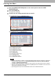
2 SETTING ITEMS (ADMIN) 3 Select the server for which you want to check, and press [ping] or [TRACEROUTE]. The check result is displayed. When the ping function is performed, the following screen will be displayed. When the traceroute function is performed, the following screen will be displayed. When the ping/traceroute command can reach a server, the IP address is displayed for the check result for the server.
2 SETTING ITEMS (ADMIN) 2.SETTING ITEMS (ADMIN) There are two ways to select the server you want to check. To select the desired server from the server list displayed on the touch panel: Checkable servers and supported protocols are as follows.
2 SETTING ITEMS (ADMIN) Setting Copy Functions You can change the system behavior for the copy operation, such as the maximum number of copies, auto 2-sided mode, and the sort mode priority. 1 Press [COPY] in the ADMIN menu (1/2). The COPY screen is displayed. To display the ADMIN menu, see the following page: P.75 “Entering Admin Menu” 2 Specify the following items as required and press . MAXIMUM COPIES — Press the number button that indicates the maximum number of copies to be allowed.
2 SETTING ITEMS (ADMIN) 2.SETTING ITEMS (ADMIN) 3 Specify the following items as required, and press . AUTOMATIC CHANGE OF PAPER SOURCE — Selecting [ON] for this function allows the equipment to feed the same size of paper from a different drawer even if the specified drawer from which paper is being fed is empty. This function is always enabled when copy operations are performed using Automatic Paper Selection (APS). To learn more about APS, refer to the Copying Guide “Chapter 3: BASIC COPY MODES”.
2 SETTING ITEMS (ADMIN) 4 Specify the following items as required, and press [OK]. AUTO EXIT TRAY CHANGE (CASCADE PRINT) — Selecting [ON] for this function allows the equipment to automatically change the output tray and continue printing when the one specified becomes full. When [OFF] is selected, the equipment will stop printing.
2 SETTING ITEMS (ADMIN) Setting Fax Functions If the FAX Unit and the 2nd Line for FAX Unit (both units are optional) are not installed, only the following option is available: “Discard and Reduction Print” option for RX Print. For details on other fax options, refer to the GD-1250/ GD-1260/GD-1270 Operator’s Manual for FAX Unit “Chapter 6: SETTING ITEMS”. y If the FAX Unit (optional) is not installed, the setting items in this menu are applied to received Internet Fax jobs.
2 SETTING ITEMS (ADMIN) 3 Press [ON] or [OFF] for each item as required and press [OK]. The registered items can be confirmed in FUNCTION LIST. P.
2 SETTING ITEMS (ADMIN) Setting File Functions This function allows you to automatically delete files stored by the Scan to File operation. This function is used to periodically delete stored files in local storage to maintain available hard disk space. 1 Press [FILE] in the ADMIN menu (1/2). The MAINTENANCE screen is displayed. To display the ADMIN menu, see the following page: P.75 “Entering Admin Menu” 2 Enable the storage maintenance function and complete the setting. 1) Press [ON].
2 SETTING ITEMS (ADMIN) Setting E-mail Functions This function allows you to set the following items. For the e-STUDIO456 Series or e-STUDIO856 Series, [E-MAIL] is available only when the Scanner Kit (optional) or Printer/Scanner Kit (optional) is installed. y E-mail Message Properties You can configure the following message properties of e-mail documents that will be sent by the Scan to E-mail operation.
2 SETTING ITEMS (ADMIN) 2.SETTING ITEMS (ADMIN) 2 Specify the following items as required and press [OK]. [FROM ADDRESS] — Press this button to enter the e-mail address of this equipment. [FROM NAME] — Press this button to enter the identification name of this equipment. [SUBJECT] — Press this button to set the default e-mail subject. The E-MAIL SUBJECT screen appears. For details of this screen, see “Operations in the E-MAIL SUBJECT screen” below.
2 SETTING ITEMS (ADMIN) panel to enter numerals.
2 SETTING ITEMS (ADMIN) Setting Internet Fax Functions This function allows you to set the following items. For the e-STUDIO456 Series or e-STUDIO856 Series, [INTERNET FAX] is available only when the Scanner Kit (optional) or Printer/Scanner Kit (optional) is installed. y Internet Fax Message Properties You can configure the following message properties of Internet Faxes that will be sent by Internet Fax transmission.
2 SETTING ITEMS (ADMIN) 2 Specify the following items as required and press [OK]. [FROM ADDRESS] — Press this button to enter the e-mail address of this equipment. [FROM NAME] — Press this button to enter the identification name of this equipment. [BODY] — Press this button to enter the body message. FRAGMENT PAGE SIZE (KB) — Select the desired fragment size from the drop-down list. Press [NONE] to disable the fragmentation.
2 SETTING ITEMS (ADMIN) Setting Security Functions This menu allows you to perform the following operations: y P.177 “Managing certificates” y P.185 “Setting secure PDF” y P.187 “Performing the integrity check” Managing certificates This menu allows you to import device certificates and CA certificates, and also export device certificates. 1 Press [SECURITY] in the ADMIN menu (1/2). The SECURITY menu is displayed. To display the ADMIN menu, see the following page: P.
2 SETTING ITEMS (ADMIN) 3 Continue the operation that you require. P.178 “Importing the device certificate” P.181 “Importing the CA certificate” P.183 “Exporting the device certificate” When importing certificates into the equipment, store the files that you want to import in the root directory of your USB storage device in advance. Importing the device certificate 1 Press [IMPORT]. The IMPORT CERTIFICATE screen is displayed. 2 Press [DEVICE CERTIFICATE].
2 SETTING ITEMS (ADMIN) 2.SETTING ITEMS (ADMIN) 3 Connect your USB storage device in which the device certificates are stored to the USB port on the equipment, and [OK]. The screen for choosing a file is displayed. For the location of the USB port on the equipment, refer to the Quick Start Guide “Chapter 1: PREPARATIONS”. 4 Select the certificate that you want to import, and press [OK]. y When the file extension is “.pfx” or “.p12”, the PASSWORD REQUIRED screen will be displayed.
2 SETTING ITEMS (ADMIN) 6 Enter the password and press [OK]. y The input password appears as asterisks (*). You can also use the digital keys on the control panel to enter numerals. y You will be returned to the PASSWORD REQUIRED screen. 7 Press [OK]. Importing the certificate begins. Do not disconnect the USB storage device until the data transfer is complete. Removing the device while data are being transferred could destroy them or cause a malfunction of the equipment.
2 SETTING ITEMS (ADMIN) 2.SETTING ITEMS (ADMIN) Importing the CA certificate 1 Press [IMPORT]. The IMPORT CERTIFICATE screen is displayed. 2 Press [CA CERTIFICATE]. The CA CERTIFICATE screen is displayed. 3 Select the encoding method for the CA certificate. A message appears prompting you to insert the USB media.
2 SETTING ITEMS (ADMIN) 4 Connect your USB storage device in which the CA certificates are stored to the USB port on the equipment, and [OK]. The screen for choosing a file is displayed. For the location of the USB port on the equipment, refer to the Quick Start Guide “Chapter 1: PREPARATIONS”. 5 Select the certificate that you want to import, and press [OK]. Importing the certificate begins. Do not disconnect the USB storage device until the data transfer is complete.
2 SETTING ITEMS (ADMIN) 2.SETTING ITEMS (ADMIN) Exporting the device certificate The file extension for exporting the device certificate is PEM (.crt). 1 Press [EXPORT]. A message appears prompting you to insert the USB media. 2 Connect your USB storage device to the USB port on the equipment, and press [OK]. The EXPORT CERTIFICATE screen is displayed. For the location of the USB port on the equipment, refer to the Quick Start Guide “Chapter 1: PREPARATIONS”. 3 Press [DEVICE CERTIFICATE].
2 SETTING ITEMS (ADMIN) 4 When exporting the certificate is complete, press [OK]. You will be returned to the SECURITY screen. 5 184 Disconnect the USB storage device from the USB port on the equipment.
2 SETTING ITEMS (ADMIN) 2.SETTING ITEMS (ADMIN) Setting secure PDF You can configure the default values for the encryption setting that is applied when data scanned on this equipment is generated as a secure PDF file. You can also configure whether or not to use the forced encryption mode. This setting is applied to operations for “Scan to File or USB” and “Scan to E-mail”. 1 Press [SECURITY] in the ADMIN menu. The SECURITY screen is displayed. To display the ADMIN menu, see the following page: P.
2 SETTING ITEMS (ADMIN) 3 Specify the following items as required and press [OK]. [USER PASSWORD] — Press this button to enter a password required to open a secure PDF file. No user password is initially set. USE AUTHENTICATION CODE AS PASSWORD — Press [ENABLE] to use a user authentication user name for [USER PASSWORD] or [DISABLE] to use a password entered in the [USER PASSWORD] box. [MASTER PASSWORD] — Press this button to enter a password required to change the security setting of a secure PDF file.
2 SETTING ITEMS (ADMIN) 2.SETTING ITEMS (ADMIN) Performing the integrity check This menu allows you to perform the following integrity check operations. y [MINIMUM] Selecting [MINIMUM] checks the execution code to run the security function and the data to which the security execution code refers. y [FULL] Selecting [FULL] checks all execution codes and the data to which the security execution code refers. 1 Press [SECURITY] in the ADMIN menu (1/2). The SECURITY menu is displayed.
2 SETTING ITEMS (ADMIN) Checking the minimum required data 1 Press [MINIMUM]. The message “Are you sure ?” is displayed in the CONFIRMATION screen. 2 Press [OK]. When the integrity check is complete, the message “The process was finished successfully” will be displayed in the CONFIRMATION screen. y It may take a long time to complete the integrity check.
2 SETTING ITEMS (ADMIN) 2.SETTING ITEMS (ADMIN) Checking all data 1 Press [FULL]. The message “Are you sure ?” is displayed in the CONFIRMATION screen. 2 Press [OK]. When the integrity check is complete, the message “The process was finished successfully” will be displayed in the CONFIRMATION screen. y It may take a long time to complete the integrity check.
2 SETTING ITEMS (ADMIN) Setting List/Report This menu allows you to make required settings for printing the following reports: y Transmission / Reception Journal There are two types of journals available on this equipment. Journals can be printed either automatically or manually. This function allows you to set auto-print for the journals, and the number of transactions appears in the journal list.
2 SETTING ITEMS (ADMIN) 2.SETTING ITEMS (ADMIN) 3 Continue the operation that you require. P.191 “Setting the transmission / reception journal” P.192 “Setting the communication report” P.194 “Setting the reception list” Setting the transmission / reception journal 1 Press [JOURNAL]. The JOURNAL screen is displayed. 2 Specify the following items as required and press [OK]. AUTO — Press [ON] to enable printing the transmission and reception journals automatically.
2 SETTING ITEMS (ADMIN) Setting the communication report 1 Press [COMM. REPORT]. The COMM. REPORT screen is displayed. 2 Specify the conditions for each transmission type and press . [OFF] — Press this button to disable printing the communication report. [ALWAYS] — Press this button to print a communication report for every transmission. [ON ERROR] — Press this button to print a communication report only when an error occurs.
2 SETTING ITEMS (ADMIN) 2.SETTING ITEMS (ADMIN) 3 Specify the conditions for each transmission type and press [OK]. The RELAY ORIGINATION, RELAY STATION and RELAY DESTINATION settings are available only when the FAX Unit (optional) is installed. When you press [ALWAYS] or [ON ERROR] for each transmission type, the “Print 1st page image?” message is displayed. Press [YES] to print the communication report with the first page image, or press [NO] to print the communication report without the page image.
2 SETTING ITEMS (ADMIN) Setting the reception list 1 Press [RECEPTION LIST]. The RECEPTION LIST screen is displayed. 2 Specify whether the reception list will be printed for each transmission and press [OK]. RELAY STATION — Select [ON] to print the reception list when receiving a relay transmission from an originator. LOCAL — Select [ON] to print the reception list when reserving a document to a mailbox within the machine locally.
2 SETTING ITEMS (ADMIN) Printing Lists This menu allows you to print NIC CONFIGURATION PAGE, FUNCTION LIST, PS3 FONT LIST, and PCL FONT LIST. * For examples of each list format, see the following page: P.246 “List Print Format” 1 Press [LIST/REPORT] in the ADMIN menu (1/2). The LIST/REPORT screen is displayed. To display the ADMIN menu, see the following page: P.75 “Entering Admin Menu” 2 Press [LIST]. The LIST screen is displayed. 3 Press the button for the list that you want to print.
2 SETTING ITEMS (ADMIN) Setting Printer/e-Filing Functions This menu allows you to make settings for the printer and e-Filing functions that will apply to the print jobs or e-Filing jobs. 1 Press [PRINTER/e-FILING] in the ADMIN menu (1/2). The PRINTER/E-FILING screen is displayed. To display the ADMIN menu, see the following page: P.
2 SETTING ITEMS (ADMIN) 2.SETTING ITEMS (ADMIN) 2 Specify the following items as required and press . AUTOMATIC CHANGE OF PAPER SOURCE — Selecting [ON] for this function allows the equipment to feed the same size of paper from a different drawer even if the specified drawer from which paper is being fed is empty. This function is always enabled when print operations are performed by selecting [Auto] for the paper source on the print dialog box.
2 SETTING ITEMS (ADMIN) 3 Specify the following items as required, and press [OK]. AUTO EXIT TRAY CHANGE (CASCADE PRINT) — Selecting [ON] for this function allows the equipment to automatically change an output tray and continue printing when the output tray you specified becomes full. When [OFF] is selected, the equipment will stop printing in that case.
2 SETTING ITEMS (ADMIN) Wireless Settings and Bluetooth Settings There is also [WIRELESS SETTING] in the ADMIN menu. This button will be available only when the Wireless LAN Module (optional) is installed. For instructions on how to operate [WIRELESS SETTING], refer to the GN-1060 Operator’s Manual for Wireless LAN Module “Chapter 1: SETTING UP WIRELESS NETWORK”. There is also [Bluetooth SETTINGS] in the ADMIN menu. This button will be available only when the Bluetooth Module (optional) is installed.
2 SETTING ITEMS (ADMIN) Change User Password When the MFP Local Authentication feature is used, administrators can change the authentication password assigned for each user in case it is forgotten. 1 Press [CHANGE USER PASSWORD] on the ADMIN menu (1/2). The CHANGE USER PASSWORD screen is displayed. To display the ADMIN menu, see the following page: P.75 “Entering Admin Menu” [CHANGE USER PASSWORD] is available only when the MFP Local Authentication feature is enabled.
2 SETTING ITEMS (ADMIN) IEEE 802.1X Authentication Setting This menu allows you to make settings for IEEE 802.1X authentication that will apply to wired networks.
2 SETTING ITEMS (ADMIN) 2 Specify the following items as required and press [Next]. 802.1X — Press [ENABLE] to enable IEEE802.1X authentication, or [DISABLE] to disable it. [CHECK SETTINGS] — Press this button to confirm the options currently selected. [FACTORY DEFAULT] — Press this button to reset the IEEE802.1X authentication settings back to the factory defaults. [CHECK SETTINGS] is available when you enable IEEE802.1X authentication. When changing IEEE802.
2 SETTING ITEMS (ADMIN) 2.SETTING ITEMS (ADMIN) Setting EAP-MSCHAPv2 1 Select [EAP-MSCHAPv2] and press [Next]. The WIRED 802.1X SETTINGS (EAP-MSCHAPv2) screen is displayed. 2 Specify the following items as required and press [Next]. [EAP USER NAME] — Press this button to enter the EAP User name. [PASSWORD] — Press this button to enter the authentication password. [RETYPE PASSWORD] — Press this button to re-enter the authentication password.
2 SETTING ITEMS (ADMIN) Setting EAP-MD5 1 Select [EAP-MD5] and press [Next]. The WIRED 802.1X SETTINGS (EAP-MD5) screen is displayed. 2 Specify the following items as required and press [Next]. [EAP USER NAME] — Press this button to enter the EAP User name. [PASSWORD] — Press this button to enter the authentication password. [RETYPE PASSWORD] — Press this button to re-enter the authentication password. When you press the above buttons, the on-screen keyboard is displayed.
2 SETTING ITEMS (ADMIN) 2.SETTING ITEMS (ADMIN) Setting EAP-TLS The CA certificate and user certificate must be installed in this equipment before the settings for IEEE 802.1X authentication are performed. For instructions on how to install the certificates, refer to the TopAccess Guide “Chapter 8: [Administration] Tab Page”. 1 Select [EAP-TLS] and press [Next]. The WIRED 802.1X SETTINGS (EAP-TLS) screen is displayed. 2 Specify the following items as required and press [Next].
2 SETTING ITEMS (ADMIN) 3 Confirm the settings and press [APPLY NOW]. “NETWORK INITIALIZING” is displayed at the lower left of the screen and this equipment starts initializing the network interface card to apply the changes. This message disappears after it is finished. 206 IEEE 802.
2 SETTING ITEMS (ADMIN) 2.SETTING ITEMS (ADMIN) Setting PEAP y The CA certificate must be installed in this equipment before the settings for IEEE 802.1X authentication are performed. For instructions on how to install the certificate, refer to the TopAccess Guide “Chapter 8: [Administration] Tab Page”. y PEAP is not available for Windows Server 2008. 1 Select [PEAP] and press [Next]. The WIRED 802.1X SETTINGS (PEAP) screen is displayed.
2 SETTING ITEMS (ADMIN) 3 Specify the following items as required and press [Next]. [EAP USER NAME] — Press this button to enter the EAP User name. [PASSWORD] — Press this button to enter the authentication password. [RETYPE PASSWORD] — Press this button to re-enter the authentication password. When you press the above buttons, the on-screen keyboard is displayed. Enter the value using the on-screen keyboard and press [OK] to set the entry.
2 SETTING ITEMS (ADMIN) 2.SETTING ITEMS (ADMIN) Setting EAP-TTLS The CA certificate must be installed in this equipment before the settings for IEEE 802.1X authentication are performed. For instructions on how to install the certificate, refer to the TopAccess Guide “Chapter 8: [Administration] Tab Page”. 1 Select [EAP-TTLS] and press [Next]. The WIRED 802.1X SETTINGS (EAP-TTLS) screen is displayed. 2 Select the desired inner authentication method and continue the operation that you require. P.
2 SETTING ITEMS (ADMIN) 2 Specify the following items as required and press [Next]. [EAP USER NAME] — Press this button to enter the EAP User Name. [PASSWORD] — Press this button to enter the authentication password. [RETYPE PASSWORD] — Press this button to re-enter the authentication password. When you press the above buttons, the on-screen keyboard is displayed. Enter the value using the on-screen keyboard and press [OK] to set the entry.
2 SETTING ITEMS (ADMIN) 2.SETTING ITEMS (ADMIN) 2 Specify the following items as required and press [Next]. [EAP USER NAME] — Press this button to enter the EAP User name. [PASSWORD] — Press this button to enter the authentication password. [RETYPE PASSWORD] — Press this button to re-enter the authentication password. When you press the above buttons, the on-screen keyboard is displayed. Enter the value using the on-screen keyboard and press [OK] to set the entry.
2 SETTING ITEMS (ADMIN) 2 Specify the following items as required and press [Next]. [EAP USER NAME] — Press this button to enter the EAP User name. [PASSWORD] — Press this button to enter the authentication password. [RETYPE PASSWORD] — Press this button to re-enter the authentication password. When you press the above buttons, the on-screen keyboard is displayed. Enter the value using the on-screen keyboard and press [OK] to set the entry.
2 SETTING ITEMS (ADMIN) 2.SETTING ITEMS (ADMIN) 2 Specify the following items as required and press [Next]. [EAP USER NAME] — Press this button to enter the EAP User name. [PASSWORD] — Press this button to enter the authentication password. [RETYPE PASSWORD] — Press this button to re-enter the authentication password. When you press the above buttons, the on-screen keyboard is displayed. Enter the value using the on-screen keyboard and press [OK] to set the entry.
2 SETTING ITEMS (ADMIN) Error messages The following error messages may be displayed on the touch panel. Message 214 Cause [802.1X] Auth Server/Switch couldn’t be contacted y The RADIUS server service is stopped. y Configuration for the RADIUS server is not correct. y The IEEE 802.1X switch has problem. [802.1X] Authentication failed y The username or password that the user entered is not correct. y The certificates uploaded are wrong.
2 SETTING ITEMS (ADMIN) Resetting the equipment settings back to the factory defaults This menu allows you to reset the equipment settings back to the factory defaults, and also clear the user data. The data to be reset by this operation are as follows: Settings Data Setup Remarks General All the settings are reset to the factory defaults.
2 SETTING ITEMS (ADMIN) 2 Press [FACTORY DEFAULT]. The message asking you to initialize the equipment settings is displayed. 3 Press [OK]. The initialization begins. y If you want to back up the setting data and user data before initialization, use the cloning function to make duplicate files. For details on the cloning function, see the following page: P.117 “Creating or installing cloning files” y When the initialization fails, the message “The process failed.” will be displayed.
MANAGING COUNTERS (COUNTER MENU) 3. Total Counter ........................................................................................................................ 218 Print Out Total Counter ........................................................................................................ 221 Department Counter............................................................................................................. 222 Managing Department Codes.............................................
3 MANAGING COUNTERS (COUNTER MENU) Total Counter This menu allows you to display and confirm the following total counters: y Print counter The print counter contains the following counters: - Copy counter — Indicates the number of sheets that have been printed by copy operations. - Fax counter — Indicates the number of sheets that have been printed by fax receptions.
3 MANAGING COUNTERS (COUNTER MENU) 3.MANAGING COUNTERS (COUNTER MENU) Displaying print counter 1 Press [PRINT COUNTER]. The PRINT COUNTER screen is displayed. 2 Select the function button whose counter you want to check. (Only for the color print models) The displayed items differ between the color print models and the other ones. Displaying scan counter 1 Press [SCAN COUNTER]. The SCAN COUNTER screen is displayed.
3 MANAGING COUNTERS (COUNTER MENU) 2 220 Select the function button whose counter you want to check.
3 MANAGING COUNTERS (COUNTER MENU) Print Out Total Counter This menu allows you to print TOTAL COUNTER LIST. 1 2 Press the [COUNTER] button on the control panel to enter the COUNTER menu. Press [PRINT OUT TOTAL COUNTER]. y When the Department Management feature is disabled, TOTAL COUNTER LIST is printed. y When the Department Management feature is enabled, the screen to input the department code is displayed. Enter the department code using the digital keys and press [OK] to print TOTAL COUNTER LIST.
3 MANAGING COUNTERS (COUNTER MENU) Department Counter This menu allows you to display and confirm the following counters for each department: The department counter is available only when this equipment has been managed using the department code. P.229 “Enabling department codes” y Print counter for department code This feature allows you to display the number of the print counter for each department code.
3 MANAGING COUNTERS (COUNTER MENU) 3.MANAGING COUNTERS (COUNTER MENU) 4 Enter the department code and press [OK]. You will be returned to the DEPARTMENT CODE screen. 5 Press [OK]. The COUNTER screen is displayed. 6 Continue the operation that you require. P.224 “Displaying print counter for department code” P.224 “Displaying scan counter for department code” P.
3 MANAGING COUNTERS (COUNTER MENU) Displaying print counter for department code 1 Press [PRINT COUNTER]. The PRINT COUNTER screen for the specified department code is displayed. 2 Select the function button whose counter you want to check. (Only for the color print models) The displayed items differ between the color print models and the other ones. Displaying scan counter for department code 1 Press [SCAN COUNTER]. The SCAN COUNTER screen for the specified department code is displayed.
3 MANAGING COUNTERS (COUNTER MENU) 3.MANAGING COUNTERS (COUNTER MENU) 2 Select the function button whose counter you want to check. Displaying fax communications counter for department code 1 Press [FAX COMMUNICATION]. The FAX COMMUNICATION screen for the specified department code is displayed.
3 MANAGING COUNTERS (COUNTER MENU) Managing Department Codes Logging on as administrator You can audit the copy quantity of copy, print, scan, and facsimile pages performed by setting a department code. Up to 1000 department codes can be registered. To manage the department codes, you must know the administrator password for this equipment. It is recommended that this action be performed only by an authorized administrator.
3 MANAGING COUNTERS (COUNTER MENU) 3.MANAGING COUNTERS (COUNTER MENU) 4 Enter the administrator password and press [OK]. The DEPT. MANAGEMENT menu is displayed. y If the administrator password has not been changed before, enter the default administrator password “123456”. y The input password appears as asterisks (*). You can also use the digital keys on the control panel to enter numerals. 5 Continue the operation that you require. P.228 “Printing DEPARTMENT CODE LIST” P.
3 MANAGING COUNTERS (COUNTER MENU) Printing DEPARTMENT CODE LIST You can print out the department code list and counters for each department code. 1 In the DEPT. MANAGEMENT menu, press [PRINT OUT DEPARTMENT CODES]. Printing begins. y For instructions on how to display the screen above, see the following page: P.226 “Logging on as administrator” y For an output example of DEPARTMENT CODE LIST, see the following page: P.
3 MANAGING COUNTERS (COUNTER MENU) 3.MANAGING COUNTERS (COUNTER MENU) Enabling department codes In the initial setting, the Department Management feature is disabled. If you want to manage the counter separately by department codes, you must enable this feature. When the Department Management feature is enabled, the department code input screen will be displayed before entering the copy, scan, fax, and e-Filing operation screens to manage the operations for each department code.
3 MANAGING COUNTERS (COUNTER MENU) Registering a new department code This function allows you to register new department codes. After registering the department code(s), you must enable the Department Management function. P.229 “Enabling department codes” 1 In the DEPT. MANAGEMENT menu, press [DEPARTMENT REGISTRATION]. The DEPARTMENT CODE screen is displayed. For instructions on how to display the screen above, see the following page: P.
3 MANAGING COUNTERS (COUNTER MENU) 3.MANAGING COUNTERS (COUNTER MENU) 3 Enter the department name, and press [OK]. The REGISTER DEPARTMENT CODE screen is displayed. You can also use the digital keys on the control panel to enter numerals. 4 Press [NEW CODE]. The on-screen keyboard is displayed. 5 Enter the department code, and press [OK]. You will be returned to the REGISTER DEPARTMENT CODE screen. Up to 63 characters can be entered for a department code.
3 MANAGING COUNTERS (COUNTER MENU) 6 Press [OK]. The QUOTA screen is displayed. 7 Set the quota of this department code as required, and press [OK] to register the new department code. You will be returned to the DEPARTMENT CODE screen. QUOTA MANAGEMENT — The quota setting is enabled or disabled by pressing [ON] or [OFF]. To enable it, press [ON] and set the quota and the default quota value. (In the color print models, set the color and the black quota respectively.
3 MANAGING COUNTERS (COUNTER MENU) 3.MANAGING COUNTERS (COUNTER MENU) Editing department codes This function allows you to edit an existing department code. 1 In the DEPT. MANAGEMENT menu, press [DEPARTMENT REGISTRATION]. The DEPARTMENT CODE screen is displayed. For instructions on how to display the screen above, see the following page: P.226 “Logging on as administrator” 2 Press the department button that you want to edit and press [EDIT]. The message “This department code is already registered.
3 MANAGING COUNTERS (COUNTER MENU) 4 Enter a new department name if necessary, and press [OK]. If you do not need to change the department name, press [OK] without changing it. The department code currently set is displayed in the EDIT DEPARTMENT CODE screen. You can also use the digital keys on the control panel to enter numerals. 5 Press [NEW CODE]. The on-screen keyboard is displayed. 6 Enter a new department code, and press [OK]. You will be returned to the EDIT DEPARTMENT CODE screen.
3 MANAGING COUNTERS (COUNTER MENU) 3.MANAGING COUNTERS (COUNTER MENU) 7 Press [OK]. The QUOTA screen is displayed. 8 Set the quota of this department code as required, and press [OK]. For the description of each item, see step 7 in the following operation: P.
3 MANAGING COUNTERS (COUNTER MENU) Deleting department codes This function allows you to delete an existing department code. 1 In the DEPT. MANAGEMENT menu, press [DEPARTMENT REGISTRATION]. The DEPARTMENT CODE screen is displayed. For instructions on how to display the screen above, see the following page: P.226 “Logging on as administrator” 2 Press the department button that you want to delete and press [DELETE]. The message “Delete OK?” is displayed in the CONFIRMATION screen.
3 MANAGING COUNTERS (COUNTER MENU) 3.MANAGING COUNTERS (COUNTER MENU) 3 Press [YES]. The department code is now deleted. Press [NO] to cancel the deletion. Resetting the counter for each department This function allows you to reset the counter for the specified department code. 1 In the DEPT. MANAGEMENT menu, press [DEPARTMENT REGISTRATION]. The DEPARTMENT CODE screen is displayed. For instructions on how to display the screen above, see the following page: P.
3 MANAGING COUNTERS (COUNTER MENU) 2 Press the department button whose counter you want to reset and press [RESET COUNTERS]. The message “CLEAR OK?” is displayed in the CONFIRMATION screen. If the touch panel does not display the department code whose counter you want to clear, press the next screen. 3 Press [YES]. The counter is now cleared. Press [NO] to cancel the clear operation.
3 MANAGING COUNTERS (COUNTER MENU) 3.MANAGING COUNTERS (COUNTER MENU) Setting output limitations for all departments This function allows you to set the output limitations for all departments through a single operation. When you select [ON], output will be disabled for all departments. When you select [OFF], unlimited outputs will be allowed for all departments. When you select [ON] in this menu, the quota settings for all department codes will be set to “0”.
3 MANAGING COUNTERS (COUNTER MENU) Setting the No Limit Black function “No Limit Black” is the function for allowing users to perform black copying/printing without entering a department code. When you want to manage only color outputs for each department code, enable this function to allow users to perform unlimited black copies/prints on the equipment. When you enable it, the equipment will not count the number of black copies/prints for each department code.
3 MANAGING COUNTERS (COUNTER MENU) 3.MANAGING COUNTERS (COUNTER MENU) Setting the registered quota This function allows you to return the quotas for all departments to the default ones through a single operation. 1 In the DEPT. MANAGEMENT menu, press [SET REGISTERED QUOTA]. The message “Are you sure?” is displayed in the CONFIRMATION screen. For instructions on how to display the screen above, see the following page: P.226 “Logging on as administrator” 2 Press [YES].
3 MANAGING COUNTERS (COUNTER MENU) Resetting all department counters This function clears all department counters to “0”. This function clears only the department counters. You cannot clear the total counter. 1 In the DEPT. MANAGEMENT menu, press [RESET ALL COUNTERS]. The message “CLEAR OK?” is displayed in the CONFIRMATION screen. For instructions on how to display the screen above, see the following page: P.226 “Logging on as administrator” 2 Press [YES].
3 MANAGING COUNTERS (COUNTER MENU) 3.MANAGING COUNTERS (COUNTER MENU) Deleting all department codes This function deletes all registered department codes. 1 In the DEPT. MANAGEMENT menu, press [DELETE ALL]. The message “Delete OK?” is displayed in the CONFIRMATION screen. For instructions on how to display the screen above, see the following page: P.226 “Logging on as administrator” 2 Press [YES]. All department codes are now deleted. Press [NO] to cancel the deletion.
APPENDIX 4. List Print Format................................................................................................................... 246 TOTAL COUNTER LIST.....................................................................................................................................246 DEPARTMENT CODE LIST ...............................................................................................................................247 ADDRESS BOOK INFORMATION..............................
4 APPENDIX List Print Format TOTAL COUNTER LIST Output example of TOTAL COUNTER LIST (e-STUDIO4540C Series) TOTAL COUNTER LIST 2011-05-10 15:18 PRINT COUNTER TOTAL FIN S/N:FIN S/N- TOTAL :9999 DF TOTAL :9999 FULL COLOR TWIN/MONO COLOR BLACK TOTAL 99999 99999 99999 99999 99999 99999 99999 99999 99999 99999 99999 99999 299996 299996 299996 299996 399996 399996 399996 1199988 FULL COLOR TWIN/MONO COLOR BLACK TOTAL SMALL LARGE 16667 16667 16666 16665 16667 16667 399996 399996 TOTAL
4 APPENDIX 4.APPENDIX DEPARTMENT CODE LIST Output example of DEPARTMENT CODE LIST (e-STUDIO4540C Series) DEPARTMENT CODE LIST TIME DEPT NO. DEPARTMENT D 1 : 2011-05-10 10:53 QUOTA 01 999.
4 APPENDIX ADDRESS BOOK INFORMATION Output example of ADDRESS BOOK INFORMATION ADDRESS BOOK INFORMATION 248 : 2011-05-10 20:47 FAX NO.1 : 99999999999 FAX NO.2 : 99999999990 NAME : MFP_00000183 NO. NAME 001 User01 00000000001 user01@example.com OFF MEMORY OFF 0 002 User02 00000000002 user02@example.com OFF MEMORY OFF 0 003 User03 00000000003 user03@example.com OFF MEMORY OFF 0 004 User04 00000000004 user04@example.
4 APPENDIX 4.APPENDIX GROUP NUMBER INFORMATION Output example of GROUP NUMBER INFORMATION GROUP NUMBER INFORMATION NO. NAME 001 Group01 TIME : 2011-05-10 20:47 FAX NO.1 : 99999999999 FAX NO.
4 APPENDIX FUNCTION LIST (User) Output example of FUNCTION LIST (User) (e-STUDIO4540C Series) FUNCTION LIST S/N : CME000034 TIME : 2011-05-10 20:47 F/W Ver. : T140SY0W0020 FAX NO.1 : 99999999999 M-ROM Ver. : 140M-015 FAX NO.2 : 99999999990 S-ROM Ver.
4 APPENDIX 4.
4 APPENDIX IP Address The IP address of this equipment Subnet Mask The subnet mask of this equipment Default Gateway The default gateway of this equipment Primary DNS Server The primary DNS server address of this equipment DNS Name The DNS name of this equipment Host Name The host name of this equipment Primary WINS Server The primary WINS server address of this equipment NetBIOS Name The NetBIOS name of this equipment IPP Network Information IPP without SSL URL for the IPP printing IPP w
4 APPENDIX 4.APPENDIX FUNCTION LIST (Administrator) Output example of FUNCTION LIST (Administrator) (e-STUDIO4540C Series) FUNCTION LIST S/N : CME000034 TIME : 2011-05-10 20:47 F/W Ver. : T140SY0W0030 FAX NO.1 : 99999999999 M-ROM Ver. : 140M-015 FAX NO.2 : 99999999990 S-ROM Ver.
4 APPENDIX GENERAL Function Description User Shows the time (in seconds) it takes the touch panel display to clear the previous settings and return to the initial screen. NO Shows the time to enter the energy saver mode (ON time), and the time to exit the energy saver mode (OFF time) for each day (Sunday to Saturday). NO ENERGY SAVER - AUTO POWER SAVE Shows the time to enter the power save mode (in minutes). NO ENERGY SAVER - SLEEP MODE Shows the time to enter the sleep mode (in minutes).
4 APPENDIX 4.APPENDIX GENERAL Function Description User FUNCTIONS - NETWORK INTERNET FAX Shows whether the network Internet fax function is enabled or disabled. NO JOB SKIP CONTROL - ENABLE JOB SKIP CONTROL Shows whether the Job Skip Control is enabled or disabled. NO ADDRESS BOOK RESTRICTION BY ADMIN Shows whether operations on the address book are restricted by the administrator authority. NO HARDCOPY SECURITY PRINTING - COPY INHIBITION Shows whether to inhibit copying the document.
4 APPENDIX COPY Function Description User MAXIMUM COPIES Shows the maximum copies that are allowed to be set. NO AUTO 2-SIDE MODE Shows the default auto 2-sided mode. NO SORT MODE PRIORITY Shows the default sort mode. NO DEFAULT MODE OF AUTO COLOR *1 Shows the default auto color mode for copies. NO AUTOMATIC CHANGE OF PAPER SOURCE Shows whether the Automatic Change of Paper Source function is enabled or disabled.
4 APPENDIX 4.APPENDIX SCAN Function Description User BLACK - RESOLUTION Shows the resolution for black scans. YES BLACK - ORIGINAL MODE Shows the default original mode for black scans. YES BLACK - EXPOSURE Shows the default exposure setting for black scans. YES BLACK - BACKGROUND ADJUSTMENT Shows the default background adjustment setting for black scans. YES *1 Printed only for the e-STUDIO6550C Series and e-STUDIO4540C Series.
4 APPENDIX FAX Function Description RECOVERY TX - STORED TIME *1 User Shows how many hours a recovery transmission job is to be stored. NO FAX RECEIVED FORWARD - AGENT1 *1 Shows the agent type if the Fax Received Forward is registered. NO FAX RECEIVED FORWARD - AGENT2 *1 Shows the agent type if the Fax Received Forward is registered. NO FAX RECEIVED FORWARD (LINE2) - AGENT1 *1 Shows the agent type of line 2 if the Fax Received Forward is registered.
4 APPENDIX 4.APPENDIX E-MAIL Function Description User NUMBER OF RETRY Shows how many times this equipment tries to send an e-mail when it had previously failed. NO RETRY INTERVAL Shows the interval of an e-mail transmission. NO BCC ADDRESS DISPLAY Shows whether Bcc address display is enabled or disabled. NO EDITING OF SUBJECT Shows whether the editing of the e-mail subject is enabled or disabled.
4 APPENDIX REPORT SETTING Function Description User RECEPTION LIST - LOCAL Shows whether a reception list will be printed or not after reserving a document to a mailbox within the equipment. NO RECEPTION LIST - REMOTE Shows whether a reception list will be printed or not after reserving a document to a mailbox within the equipment remotely from another facsimile. NO Shows whether a reception list will be printed or not after receiving a relay transmission from an originator as a relay hub.
4 APPENDIX 4.APPENDIX BLUETOOTH SETTINGS Function DATA ENCRYPTION Description User Shows whether the data encryption is enabled or disabled. NO BLUETOOTH SETTINGS are printed only when the Bluetooth Module (optional) is installed. NETWORK SETTING - GENERAL PRODUCT - GENERAL Function ETHERNET SPEED DUPLEX MODE Description User Shows the Ethernet speed setting. NO NETWORK SETTING - NETWORK - TCP/IP Function Description User ADDRESS MODE Shows the TCP/IP address mode.
4 APPENDIX NETWORK SETTING - NETWORK - IPv6 Function IP ADDRESS1 Description The IP address, prefix length and default gateway which are issued from routers.
4 APPENDIX 4.APPENDIX NETWORK SETTING - SESSION - LDAP SESSION Function Description User ENABLE LDAP Shows whether the LDAP is enabled or disabled. NO ATTRIBUTE 1 Shows the name of the schema corresponding to the LDAP server configuration. NO ATTRIBUTE 2 Shows the name of the schema corresponding to the LDAP server configuration. NO SEARCH METHOD Shows search conditions for LDAP searching.
4 APPENDIX NETWORK SETTING - SESSION - SMB SESSION Function Description User PRIMARY WINS SERVER Shows the primary WINS server address if it has been set. NO SECONDARY WINS SERVER Shows the secondary WINS server address if it has been set. NO SMB SIGNING OF SMB SERVER Shows the setting of the SMB Signing of SMB Server. NO SMB SIGNING OF SMB CLIENT Shows the setting of the SMB Signing of SMB Client.
4 APPENDIX 4.APPENDIX NETWORK SETTING - NETWORK SERVICE - HTTP NETWORK SERVICE Function SSL PORT NUMBER Description User Shows the SSL port number for the HTTP network service. NO NETWORK SETTING - NETWORK SERVICE - SMTP CLIENT NETWORK SERVICE Function Description User ENABLE SMTP CLIENT Shows whether the SMTP client is enabled or disabled. NO AUTHENTICATION Shows whether SMTP authentication is enabled or disabled. NO POP BEFORE SMTP Shows whether POP Before SMTP is enabled or disabled.
4 APPENDIX NETWORK SETTING - NETWORK SERVICE - POP3 NETWORK SERVICE Function Description User SCAN RATE Shows the scan rate to check the POP3 server for new messages (in minutes). NO PORT NUMBER Shows the port number to be used for accessing the POP3 server. NO ENABLE SSL Shows whether the SSL for the POP3 network service is enabled or disabled. NO SSL PORT NUMBER Shows the SSL port number to be used for accessing the POP3 server.
4 APPENDIX 4.APPENDIX NETWORK SETTING - NETWORK SERVICE - SNMP NETWORK SERVICE Function Description User ENABLE SNMP V3 TRAP Shows whether the SNMP V3 trap is enabled or disabled. NO ENABLE AUTHENTICATION TRAP Shows whether the authentication trap is enabled or disabled. NO ENABLE ALERTS TRAP Shows whether the alerts trap is enabled or disabled. NO IP TRAP ADDRESS1 Shows the IP address that has been set for IP trap address 1. NO IP TRAP COMMUNITY Shows the IP Trap community name.
4 APPENDIX NETWORK SETTING - PRINT SERVICE SETTING - IPP PRINT Function Description User ENABLE IPP Shows whether IPP printing is enabled or disabled. NO ENABLE PORT80 Shows whether Port80 is used for IPP printing. NO PORT NUMBER Shows the port number to be used for IPP printing. NO URL Shows the URL for IPP printing. NO AUTHENTICATION Shows whether the authentication for IPP printing is enabled or disabled. NO USER NAME Shows the user name for authentication.
4 APPENDIX 4.APPENDIX PRINT DATA CONVERTER Function ENABLE PRINT DATA CONVERTER Description User Shows whether the Print Data Converter is enabled or disabled. NO OFF DEVICE CUSTOMIZATION ARCHITECTURE Function Description User ENABLE PORT Shows whether the port is enabled or disabled. NO PORT NUMBER Shows the port number. NO ENABLE SSL Shows whether SSL is enabled or disabled. NO SSL PORT NUMBER Shows the SSL port number. NO SESSION TIMEOUT Shows the session timeout period.
4 APPENDIX SECURITY SETTING - AUTHENTICATION - EMAIL ADDRESS SETTING Function Description User FROM NAME Shows the sender's name setting. NO RESTRICTION SETTING FOR DESTINATION Shows the restriction setting for destination. NO SECURITY SETTING - AUTHENTICATION - SINGLE SIGN ON SETTING Function SINGLE SIGN ON FOR SCAN TO EMAIL Description Shows whether the Single Sign ON function is enabled or disabled.
4 APPENDIX 4.APPENDIX SECURITY SETTING - PASSWORD POLICY - POLICY FOR E-FILING, TEMPLATE GROUPS, TEMPLATES, SECURE PDF, SNMP V3, CLONING, SECURE RECEIVE Function Description User LOCKOUT SETTING Shows whether the lockout setting is enabled or disabled. NO NUMBER OF RETRY Shows the number of retry for entering the password. NO LOCKOUT TIME Shows the lockout time (minute).
4 APPENDIX PS3 font list Output example of the PS3 Font List 272 List Print Format
4 APPENDIX 4.
INDEX Numerics [1200dpi PRINT] ........................................................97 2ND TEL ...................................................................37 [600dpi PRINT] ..........................................................97 A ACS ADJUSTMENT ............................................ 18, 25 [ADDRESS BOOK] ....................................................29 ADDRESS BOOK EDIT ..............................................41 ADDRESS BOOK INFORMATION ......................
E-MAIL .....................................................................37 ENABLE APPLETALK ..............................................154 ENABLE BINDERY ..................................................150 ENABLE DHCP (IP Address) ........................... 143, 146 ENABLE DHCP (OPTIONS) .....................141, 143, 146 ENABLE HTTP SERVER ..........................................156 ENABLE IPX/SPX ....................................................148 ENABLE NDS ...............................
M PS3 font list ............................................................ 272 MAC ADDRESS FILTERING ....................................160 [MASTER PASSWORD] ...........................................186 MAXIMUM COPIES .................................................166 Message Properties ........................................ 172, 175 QUOTA MANAGEMENT .......................................... 232 N [NAME SORT] ...........................................................29 NetBIOS NAME ..........
USER ADDRESS BOOK ...................................................35 CHECK E-MAIL ......................................................70 COPY ....................................................................16 DRAWER ...............................................................31 E-FILING ...............................................................27 FAX .......................................................................22 GENERAL ............................................................
FC-5540C/6540C/6550C FC-2040C/2540C/3040C/3540C/4540C DP-2095/2530/3020/3590/4590/5010 DP-5560/6560/7560/8560 OME100058E0
MULTIFUNCTIONAL DIGITAL COLOR SYSTEMS / MULTIFUNCTIONAL DIGITAL SYSTEMS MFP Management Guide 2-17-2, HIGASHIGOTANDA, SHINAGAWA-KU, TOKYO, 141-8664, JAPAN ©2011, 2012 TOSHIBA TEC CORPORATION All rights reserved R100520J0605-TTEC Ver05 2012-06