TOSHIBA Barcode Printer B-SX8T SERIES Owner’s Manual Mode d’emploi Bedienungsanleitung Manual de instrucciones Gebruikershandleiding Manuale Utente Manual do Utilizador
CE Compliance (for EU only) This product complies with the requirements of EMC and Low Voltage Directives including their amendments. VORSICHT: • Schallemission: unter 70dB (A) nach DIN 45635 (oder ISO 7779) • Die für das Gerät Vorgesehene Steckdose muß in der Nähe des Gerätes und leicht zugänglich sein. Centronics is a registered trademark of Centronics Data Computer Corp. Microsoft is a registered trademark of Microsoft Corporation. Windows is a trademark of Microsoft Corporation.
TOSHIBA Barcode Printer B-SX8T SERIES Owner's Manual
Waste Recycling information for users: Following information is only for EU-member states: The use of the crossed-out wheeled bin symbol indicates that this product may not be treated as general household waste. By ensuring this product is disposed of correctly you will help prevent potential negative consequences for the environment and human health, which could otherwise be caused by inappropriate waste handling of this product.
This product is equipped with a wireless communication device, TRW-EUM-01 (B-SX708-RFID-U2-EU-R) Please be sure to read the enclosed precaution for handling of wireless communication devices before using this product. Precautions for Handling of Wireless Communication Devices RFID kit: TRW-EUM-01 (B-SX708-RFID-U2-EU-R) For all countries and areas This product is a wireless communication device, and the use of this product is restricted to the following countries or areas.
Safety Summary ENGLISH VERSION EO1-33057 Safety Summary Personal safety in handling or maintaining the equipment is extremely important. Warnings and Cautions necessary for safe handling are included in this manual. All warnings and cautions contained in this manual should be read and understood before handling or maintaining the equipment. Do not attempt to effect repairs or modifications to this equipment.
Safety Summary ENGLISH VERSION EO1-33057 If foreign objects (metal fragments, water, liquids) enter the machines, first turn off the power switches and disconnect the power cord plugs from the outlet, and then contact your authorised TOSHIBA TEC representative for assistance. Continued use of the machine in that condition may cause fire or electric shock. Ensure that the equipment is Connect a properly grounded. Extension grounding wire. cables should also be grounded.
ENGLISH VERSION EO1-33057 TABLE OF CONTENTS Page 1. PRODUCT OVERVIEW......................................................................................................... E1- 1 1.1 1.2 1.3 1.4 1.5 2. Introduction................................................................................................................... E1- 1 Features ....................................................................................................................... E1- 1 Accessories .......................
ENGLISH VERSION EO1-33057 4. MAINTENANCE .................................................................................................................... E4- 1 4.1 5. Cleaning ....................................................................................................................... E4- 1 4.1.1 Print Head/Platen ......................................................................................................E4- 1 4.1.2 Pinch Roller ...................................................
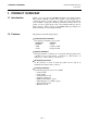
1. PRODUCT OVERVIEW ENGLISH VERSION EO1-33057 1.1 Introduction 1. PRODUCT OVERVIEW 1.1 Introduction Thank you for choosing the TOSHIBA B-SX8T series thermal printer. This Owner’s Manual contains from general set-up through how to confirm the printer operation using an online test print, and should be read carefully to help gain maximum performance and life from your printer. For most queries please refer to this manual and keep it safe for future reference.
1. PRODUCT OVERVIEW ENGLISH VERSION EO1-33057 1.3 Accessories 1.3 Accessories NOTE: As a power cord is not supplied with this printer, please purchase one that meets each country’s safety standard. For details, refer to APPENDIX 3. When unpacking the printer, please make sure all the following accessories are supplied with the printer. Start-up CD-ROM (1 pc.
1. PRODUCT OVERVIEW ENGLISH VERSION EO1-33057 1.4 Appearance 1.4 Appearance The names of the parts or units introduced in this section are used in the following chapters. 417 (16.4 ) 282 (16.4 ) 395 (15.6) 1.4.1 Dimensions Dimensions in mm (inches) 1.4.2 Front View Top Cover LCD Message Display Operation Panel Right Side Cover Head Lever Media Outlet Power Switch 0: OFF 1: ON 1.4.
1. PRODUCT OVERVIEW ENGLISH VERSION EO1-33057 1.4 Appearance 1.4.4 Operation Panel LCD Message Display POWER LED (Green) ON LINE LED (Green) ERROR LED (Red) [FEED] key [RESTART] key [PAUSE] key Please see Section 3.1 for further information about the Operation Panel. 1.4.5 Interior WARNING! 1. Do not touch the Print Head or around it just after printing. You may get burned as the Print Head becomes very hot during printing. 2. Do not touch any moving parts.
1. PRODUCT OVERVIEW ENGLISH VERSION EO1-33057 1.5 Options 1.5 Options Option Name Cutter module Strip module Type B-SX208-QM-R B-SX908-H-QM-R Serial Interface Board Wireless LAN Board Expansion I/O Board Real Time Clock B-SA704-RS-QM-R RFID module (Future Option) B-SX708-RFID-U1-US-R B-SX708-RFID-U1-EU-R B-SX708-RFID-H1-QM-R B-SX908-MC-QM-R This option is intended to protect a media roll from dirt or dust.
2. PRINTER SETUP ENGLISH VERSION EO1-33057 2. PRINTER SETUP 2. PRINTER SETUP This section outlines the procedures to setup your printer prior to its operation. The section includes precautions, loading media and ribbon, connecting cables, setting the operating environment of the printer, and performing an online print test. Setup Flow Installation Assembling the supply holder frame Procedure After referring to the Safety Precautions in this manual, install the printer on a safe and stable location.
2. PRINTER SETUP ENGLISH VERSION EO1-33057 2.1 Installation 2.1 Installation To insure the best operating environment, and to assure the safety of the operator and the equipment, please observe the following precautions. • Operate the printer on a stable, level, operating surface in a location free from excessive humidity, high temperature, dust, vibration or direct sunlight. • Keep your work environment static free. Static discharge can cause damage to delicate internal components.
2. PRINTER SETUP ENGLISH VERSION EO1-33057 2.3 Connecting the Power Cord 2.3 Connecting the Power Cord 1. Make sure that the printer Power Switch is in the OFF ({) position. Connect the Power Cord to the printer as shown in the figure below CAUTION! As a Power Cord is not supplied with the printer, please purchase an approved on that meets the safety standard of each country. (Refer to APPENDIX 3.) Power Switch Power Cord 2.
2. PRINTER SETUP ENGLISH VERSION EO1-33057 2.4 Loading the Media 2.4 Loading the Media WARNING! 1. Do not touch any moving parts. To reduce the risk of fingers, jewellery, clothing, etc., being drawn into the moving parts, be sure to load the media once the printer has stopped moving completely. 2. The Print Head becomes hot immediately after printing. Allow it to cool before loading the media. 3. Care must be taken not to pinch your fingers when opening or closing the Top Cover or Right Side Cover. 4.
2. PRINTER SETUP ENGLISH VERSION EO1-33057 2.4 Loading the Media 2.4 Loading the Media (Cont.) 4. Install the other Media Holder onto the Supply Shaft from the opposite side. Media Holder Supply Shaft 5. Turn the Locking Lever of the Media Holder to the “Close” position. Media Holder “Close” Position Locking Lever Media 6. Set the Head Lever to the “OPEN” position. “OPEN” position Head Lever 7. Open the Top Cover and the Right Side Cover. Top Cover Right Side Cover 8.
2. PRINTER SETUP ENGLISH VERSION EO1-33057 2.4 Loading the Media 2.4 Loading the Media (Cont.) 9. Loosen the Media Guide Screws on the printer back, and move the Media Guides outside. Media Guide WARNING! Be careful not to pinch your fingers or hands by the Supply Holder Frame or Media Holders when loading the media. Media Guide Screw NOTE: Place the bushes of the Supply Shaft into the notches of the Supply Holder Frame securely. Supply Holder Frame 10.
2. PRINTER SETUP ENGLISH VERSION EO1-33057 2.4 Loading the Media 2.4 Loading the Media (Cont.) NOTES: 1. When using the Movable sensor, choose the Movable sensor for the parameter setting in the system mode (Section 2.8.1 Parameter Setting). The Fixed sensor has been selected as default. 2. The position of the movable sensor should be adjusted before loading the ribbon. Otherwise, the sensor is covered by the ribbon, causing the sensor position adjustment to be disabled. 13.
2. PRINTER SETUP ENGLISH VERSION EO1-33057 2.4 Loading the Media 2.4 Loading the Media (Cont.) NOTE: Adjustment Knob Forward: Moves toward the centre of the printer. Backward: Moves away from the centre of the printer. The following procedures show how to adjust the position of the movable sensor. Feed Gap Sensor position adjustment When using a label stock without black marks, the Feed Gap Sensor is used to detect the print start position.
2. PRINTER SETUP ENGLISH VERSION EO1-33057 2.4 Loading the Media 2.4 Loading the Media (Cont.) NOTE: Be sure to set the Black Mark Sensor to detect the centre of the black mark, otherwise a paper jam or no paper error may occur. Black Mark Sensor position adjustment When using media with black marks, the Black Mark Sensor is used to detect the print start position. (1) Pull the media about 500 mm out of the front of the printer, turn the media back on it’s self and feed it under the print head.
2. PRINTER SETUP ENGLISH VERSION EO1-33057 2.4 Loading the Media 2.4 Loading the Media (Cont.) 14. There are three issue modes available on this printer. How to set the media for each mode is provided below. Batch mode In the batch mode, the media is continuously printed and fed until the number of labels/tags specified in the issue command have been printed. (1) Pull the media past the media outlet. Media Outlet (2) Turn the Pinch Roller Lever counterclockwise to lock the Pinch Roller.
2. PRINTER SETUP ENGLISH VERSION EO1-33057 2.4 Loading the Media 2.4 Loading the Media (Cont.) Strip mode (Option) When the optional Strip Module is fitted, a label is automatically removed from the backing paper at the Strip Plate as each label is printed. (1) Pull out the backing paper past the Media Outlet. Backing Paper Strip module Media Outlet WARNING! When the Backing Paper Release Bar is released, it is automatically closed by the spring. Care must be taken not to pinch your fingers or hands.
2. PRINTER SETUP ENGLISH VERSION EO1-33057 2.4 Loading the Media 2.4 Loading the Media (Cont.) WARNING! The cutter is sharp, so care must be taken not to injure your fingers when handling the cutter. CAUTION! 1. When using a label stock, be sure to cut the gaps. Cutting labels will cause the glue to stick to the cutter, which may affect the cutter quality and shorten the cutter life. 2. Use of tag paper which thickness exceeds specified value may affect the cutter life.
2. PRINTER SETUP ENGLISH VERSION EO1-33057 2.4 Loading the Media 2.4 Loading the Media (Cont.) 15. Change the print head pressure according to the thickness of the media to be used, by using the Head Lever. Head Lever Position 1 2 Media type or thickness Label or Thin media If a clear print cannot be obtained, change the position to d. Tag paper or Thick paper If a clear print cannot be obtained, change the position to c. 16.
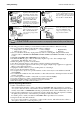
2. PRINTER SETUP ENGLISH VERSION EO1-33057 2.5 Loading the Ribbon 2.5 Loading the Ribbon WARNING! 1. Do not touch any moving parts. To reduce the risk of fingers, jewellery, clothing, etc., being drawn into the moving parts, be sure to load the ribbon once the printer has stopped moving completely. 2. The print head becomes hot immediately after printing. Allow it to cool before loading the ribbon. 3. To avoid injury, be careful not to trap your fingers while opening or closing the cover.
2. PRINTER SETUP ENGLISH VERSION EO1-33057 2.5 Loading the Ribbon 2.5 Loading the Ribbon (Cont.) 4. Fit the core of the Ribbon Supply Roll into the Ribbon Holders (Supply side), aligning the notch of the ribbon core with the protrusion of the Ribbon Holder. Ribbon Core Notch Ribbon Supply Roll Ribbon Holder (Supply Side) Fit the protrusion into the notch. Ribbon Supply Roll 5.
2. PRINTER SETUP ENGLISH VERSION EO1-33057 2.5 Loading the Ribbon 2.5 Loading the Ribbon (Cont.) 1. 2. 3. 4. 5. NOTES: Be sure to remove any slack in the ribbon when printing. Printing with a wrinkled ribbon will lower the print quality. When a ribbon end is detected, “RIBBON ERROR” message will appear on the display and the ERROR LED will illuminate. When disposing of the ribbons, please follow the local rules. For the specification of available ribbon, refer to Section 7.2 Ribbon.
2. PRINTER SETUP ENGLISH VERSION EO1-33057 2.6 Connecting the Printer to Your Host Computer 2.6 Connecting the Printer to Your Host Computer CAUTION! Do not directly connect the LAN cable which is wired outside of a building to the LAN port provided on this product, as the LAN port on this product is intended for indoor connection. To connect such LAN cable to the product, be sure to use any communication equipment, like a router, a hub, or a modem which is located within the same building as the product.
2. PRINTER SETUP ENGLISH VERSION EO1-33057 2.7 Turning the Printer ON 2.7 Turning the Printer ON CAUTION! When the printer is connected to your host computer it is good practice to turn the printer ON before turning on your host computer and turn OFF your host computer before turning off the printer. 1. To turn ON the printer power, press the Power Switch as shown in the diagram below. Note that ( | ) is the power ON side of the switch. Use the power switch to turn the printer On/Off.
2. PRINTER SETUP ENGLISH VERSION EO1-33057 2.8 Setting an Operating Environment 2.8 Setting an Operating Environment LCD Message Display FEED key RESTART key PAUSE key Depending on the settings of your host computer or an interface to be used, it may be necessary to change the printer parameter settings. Follow the procedures described below to change the printer parameter settings in the System Mode to correspond to your environment.
2. PRINTER SETUP ENGLISH VERSION EO1-33057 2.8 Setting an Operating Environment 2.8.1 Parameter Setting While “<2>PARAMETER SET” is displayed on the LCD Message Display, press the [PAUSE] key to enter the Parameter Setting Mode. The Parameter Setting Mode contains the following sub menus. Each time the [PAUSE] key is pressed, the sub menus are displayed sequentially.
2. PRINTER SETUP ENGLISH VERSION EO1-33057 2.8 Setting an Operating Environment 2.8.1 Parameter Setting (Cont.) NOTE: Be careful if the printer is turned off without pressing the [PAUSE] key, the selected value does not become effective. (1) Character Code Selection This parameter is to choose a character code used for printing. Printed characters differ depending on a chosen character code and font.
2. PRINTER SETUP ENGLISH VERSION EO1-33057 2.8 Setting an Operating Environment 2.8.1 Parameter Setting (Cont.) (3) Baud Rate Selection This parameter is to choose a baud rate of the RS-232C interface. When the printer communicates with a host computer by serial interface, be sure to match the setting with the host. When “<2>PARAMETER SET” appears, press the [PAUSE] key until the following display appears. <2>PARAMETER SET SPEED 9600bps Use the [FEED] or [RESTART] key to select a desired option.
2. PRINTER SETUP ENGLISH VERSION EO1-33057 2.8 Setting an Operating Environment 2.8.1 Parameter Setting (Cont.) NOTES: 1. When using the hardware flow control, the control signals and data must be in pairs between the printer and the PC. Printer Host TD → RD RD ← TD RTS → CTS CTS ← RTS DSR → DTR DTR ← DSR Refer to the RS-232C connector’s pin layout in APPENDIX 2. Check if the printer and the PC is properly connectable with your cable 2.
2. PRINTER SETUP ENGLISH VERSION EO1-33057 2.8 Setting an Operating Environment 2.8.1 Parameter Setting (Cont.) (8) LCD Language Selection This parameter is to choose a language in which the LCD message is displayed. When “<2>PARAMETER SET” appears, press the [PAUSE] key until the following display appears. <2>PARAMETER SET LCD ENGLISH Use the [FEED] or [RESTART] key to select a desired option.
2. PRINTER SETUP ENGLISH VERSION EO1-33057 2.8 Setting an Operating Environment 2.8.1 Parameter Setting (Cont.) When ON is selected, pressing the [PAUSE] key will result that the LCD Message Display shows the stop position fine adjustment value setting screen. <2>PARAMETER SET POSITION +0.0mm [RESTART] [FEED] POSITION +5.0mm POSITION +0.0mm POSITION -5.0mm [FEED] key: Pressing the [FEED] key one time causes a –0.1mm change, up to –5.0 mm.
2. PRINTER SETUP ENGLISH VERSION EO1-33057 2.8 Setting an Operating Environment 2.8.1 Parameter Setting (Cont.) NOTES: 1. The ribbon saving function is activated when there is a 20-mm or more non-print area in the media feed direction. 2. Ribbon saving is enabled up to 4 areas per media. 3. To use the ribbon saving function for more than one area in a label/tag, there should be at least an 8-mm print area between nonprint areas where the ribbon saving is performed.
2. PRINTER SETUP ENGLISH VERSION EO1-33057 2.8 Setting an Operating Environment 2.8.1 Parameter Setting (Cont.) When “CODE MANUAL” is selected and the [PAUSE] key is pressed, the LCD display will show the setting screen of CONTROL CODE1 to CONTROL CODE3 as follows.
2. PRINTER SETUP ENGLISH VERSION EO1-33057 2.8 Setting an Operating Environment 2.8.1 Parameter Setting (Cont.) (14) Strip Wait Status Selection This parameter is to choose when the printer sends a strip wait status (05H) to a host in response to a status request command. When “<2>PARAMETER SET” appears, press the [PAUSE] key until the following display appears. <2>PARAMETER SET PEEL OFF STS OFF Use the [FEED] or [RESTART] key to select a desired option.
2. PRINTER SETUP ENGLISH VERSION EO1-33057 2.8 Setting an Operating Environment 2.8.1 Parameter Setting (Cont.) NOTE: Kanji code selection is not supported by the QM model as the Kanji ROMs are not installed. (16) KANJI Code Selection This parameter is to choose a KANJI code. When “<2>PARAMETER SET” appears, press the [PAUSE] key until the following display appears. <2>PARAMETER SET KANJI CODE TYPE1 Use the [FEED] or [RESTART] key to select a desired option.
2. PRINTER SETUP ENGLISH VERSION EO1-33057 2.8 Setting an Operating Environment 2.8.1 Parameter Setting (Cont.) NOTES: 1. It is recommended that this function should be activated when high quality printing such as bar codes printing is required. Otherwise, choose OFF. 2. When a broken element is found, the printer stops, displaying “HEAD ERROR”.
2. PRINTER SETUP ENGLISH VERSION EO1-33057 2.8 Setting an Operating Environment 2.8.1 Parameter Setting (Cont.) NOTE: When “WEB PRINTER ON” is selected, the status of the printer connected in a network can be checked through the Web browser. (20) Web Printer Function Selection This parameter is to choose whether to use the printer as a web printer. When “<2>PARAMETER SET” appears, press the [PAUSE] key until the following display appears.
2. PRINTER SETUP ENGLISH VERSION EO1-33057 2.8 Setting an Operating Environment 2.8.1 Parameter Setting (Cont.) (22) Input Prime Selection This parameter is to choose whether to enable a reset operation when INIT signal is ON. Normally, when the printer receives a reset request signal (nInit signal) from the host via Centronics interface, the printer will be reset and turn to the idle state. When the INPUT PRIME parameter is set to OFF, the printer is reset but does not turn to idle.
2. PRINTER SETUP ENGLISH VERSION EO1-33057 2.8 Setting an Operating Environment 2.8.1 Parameter Setting (Cont.) NOTE: If the printer and the PC are connected by USB, plug & play will be automatically enabled, regardless of the setting of this parameter. (24) Plug & Play Selection This parameter is to choose whether to enable a Plug & Play function. When “<2>PARAMETER SET” appears, press the [PAUSE] key until the following display appears.
2. PRINTER SETUP ENGLISH VERSION EO1-33057 2.8 Setting an Operating Environment 2.8.1 Parameter Setting (Cont.) (26) Pre-Strip Selection This parameter is to choose whether to activate the Pre Strip function. When this parameter is set to ON (Available), the top edge of a label is separated (pre-stripped) from the backing paper before the label is printed.
2. PRINTER SETUP ENGLISH VERSION EO1-33057 2.8 Setting an Operating Environment 2.8.1 Parameter Setting (Cont.) (28) Maxi Code Specification Selection This parameter is to choose a Maxi code specification. When “<2>PARAMETER SET” appears, press the [PAUSE] key until the following display appears. <2>PARAMETER SET MAXI CODE TYPE1 Use the [FEED] or [RESTART] key to select a desired option.
2. PRINTER SETUP ENGLISH VERSION EO1-33057 2.8 Setting an Operating Environment 2.8.2 Dump Mode Setting While “<4>DUMP MODE” is displayed on the LCD Message Display, press the [PAUSE] key to enter the Dump Mode. In the Dump Mode, data in the receive buffer are printed. Data are expressed in hexadecimal values. This operation allows the user to verify programming commands or debug the program. When “<4>DUMP MODE” appears, press the [PAUSE] key.
2. PRINTER SETUP ENGLISH VERSION EO1-33057 2.8 Setting an Operating Environment 2.8.2 Dump Mode Setting (Cont.) Print Conditions • Printing width: 3.9 inches (100 mm) • Sensor selection: None • Print speed: 4”/sec. • Printing mode: Depends on the selection in use. • 16 bytes/line • Data is printed in the order from the new one to the old one. • Data specified by the receive buffer write pointer will be printed in boldface.
2. PRINTER SETUP ENGLISH VERSION EO1-33057 2.8 Setting an Operating Environment 2.8.3 BASIC Expansion Mode While “<5>EXPAND MDOE” is displayed on the LCD Message Display, press the [PAUSE] key to enter the BASIC Expansion Mode. NOTE: For the BASIC enable setting mode, refer to the B-SX6T/SX8T Series Key Operation Specification stored in the CD-ROM. In the BASIC Expansion Mode, it is possible to execute the BASIC expansion mode program under the following conditions.
2. PRINTER SETUP ENGLISH VERSION EO1-33057 2.8 Setting an Operating Environment 2.8.4 Automatic Calibration While “<6>AUTO CALIB” is displayed on the LCD Message Display, press the [PAUSE] key to enter the Automatic Calibration Mode. In the Automatic Calibration Mode, whether to activate the automatic calibration at a power on time or not is selectable.
2. PRINTER SETUP ENGLISH VERSION EO1-33057 2.8 Setting an Operating Environment 2.8.5 LAN Setting While “<7>LAN” is displayed on the LCD Message Display, press the [PAUSE] key to enter the LAN Setting Mode. In the LAN Setting Mode, whether to enable the LAN communication and SNMP or not is selectable. When “<7>LAN” appears, press the [PAUSE] key. <7>LAN ON SNMP ON Use the [FEED] or [RESTART] key to select a desired option. [RESTART] OFF ON SNMP ON [FEED] ON SNMP OFF LAN is disabled.
2. PRINTER SETUP ENGLISH VERSION EO1-33057 2.8 Setting an Operating Environment 2.8.6 Real Time Clock Setting While “<8>RTC SET” is displayed on the LCD Message Display, press the [PAUSE] key to enter the Real Time Clock Setting Mode. NOTE: The Real Time Clock Setting is effective only when an optional Real Time Clock, B-SA704-RTC-QM-R, is installed. The Real Time Clock Setting Mode contains the following sub menus. Each time the [PAUSE] key is pressed, the sub menus are displayed sequentially.
2. PRINTER SETUP ENGLISH VERSION EO1-33057 2.8 Setting an Operating Environment 2.8.6 Real Time Clock Setting (3) Low Battery Check Setting This parameter is to choose whether to activate the low battery check (Cont.) function or not. NOTE: 1. Be sure to load the battery and set the low battery check function to ON whenever the real time clock is used. If the battery is not loaded or the battery voltage is low, the real time clock data is erased at the power off time. 2.
2. PRINTER SETUP ENGLISH VERSION EO1-33057 2.8 Setting an Operating Environment 2.8.7 IP Address Setting (TCP/IP) Power OFF When the printer is connected to a PC through TCP/IP by using a LAN cable, it is necessary to set an IP address in the System Mode for system administrators. The System Mode for system administrators consists of the following menus. While holding down the [FEED] and [PAUSE] keys, turn on the printer. <1>DIAG. Vx.x [FEED] <5>SENSOR ADJ.
2. PRINTER SETUP ENGLISH VERSION EO1-33057 2.8 Setting an Operating Environment 2.8.7 IP Address Setting (TCP/IP) (Cont.) In this section, how to set the IP address is described. First, you need to access the System Mode for system administrators. 1. While holding down the [FEED] and [PAUSE] keys, turn on the printer. 2. When “<1>DIAG” appears on the LCD Message Display, release the [FEED] and [PAUSE] keys. Now, the printer is in the System Mode for system administrators. 3.
2. PRINTER SETUP ENGLISH VERSION EO1-33057 2.8 Setting an Operating Environment 2.8.7 IP Address Setting (TCP/IP) (Cont.) (1) Printer IP Address This parameter is to set an IP address. <7>IP ADDRESS PRINTER IP ADRES NOTES: 1. Set each 3-digit value by using the [RESTART] or [FEED] key. [RESTART] key: Increment [FEED] key: Decrement Range: 0 to 255 2. Press the [PAUSE] key to move the cursor to the next 3-digit value. 3.
2. PRINTER SETUP ENGLISH VERSION EO1-33057 2.8 Setting an Operating Environment 2.8.7 IP Address Setting (TCP/IP) (Cont.) (3) Subnet Mask This parameter is to set a Subnet Mask. <7>IP ADDRESS SUBNET MASK NOTE: After the last 3-digit value is set, press the [PAUSE] key to go to Socket Port Setting. [PAUSE] <7>IP ADDRESS 255 . 255 . 255 . 000 [PAUSE] <7>IP ADDRESS 255 . 255 . 255 . 000 [PAUSE] <7>IP ADDRESS 255 . 255 . 255 . 000 [PAUSE] <7>IP ADDRESS 255 . 255 . 255 .
2. PRINTER SETUP ENGLISH VERSION EO1-33057 2.8 Setting an Operating Environment 2.8.7 IP Address Setting (TCP/IP) (Cont.) NOTE: Pressing the [PAUSE] key while “DHCP ON” is displayed allows you to set a DHCP client ID. 5) DHCP This parameter is to enable DHCP. <7>IP ADDRESS DHCP [PAUSE] <7>IP ADDRESS DHCP OFF [RESTART] or [FEED] <7>IP ADDRESS DHCP ON [PAUSE] <7>IP ADDRESS DHCP CLIENT ID (6) DHCP Client ID This parameter is to set a DHCP client ID. 1. 2. 3. 4.
2. PRINTER SETUP ENGLISH VERSION EO1-33057 2.8 Setting an Operating Environment 2.8.7 IP Address Setting (TCP/IP) (Cont.) (7) DHCP Host Name This parameter is to set a DHCP host name <7>IP ADDRESS DHCP HOST NAME NOTE: After the 16th byte of the DHCP host name is set, press the [PAUSE] key. At this time, the display will turn to “<7>IP ADDRESS”. [PAUSE] MODE ASCII Enter a character or a value for each of 1st byte to 16th byte sequentially using the [FEED] or [RESTART] key.
2. PRINTER SETUP ENGLISH VERSION EO1-33057 2.9 Installing the Printer Drivers 2.9 Installing the Printer Drivers 2.9.1 Introduction This manual describes how to install the TOSHIBA printer driver for the TOSHIBA bar code printer on your Windows host computer; install and delete the printer driver, the procedure for adding the LAN port, cautions and limitations. The examples provided here illustrate the procedure for installing the printer driver version V7.0 for the B-SA4T series. 2.9.
2. PRINTER SETUP ENGLISH VERSION EO1-33057 2.9 Installing the Printer Drivers 2.9.3 Installing the Printer Driver The installation procedure differs depending on the interface connected to the printer and the operation system you are using. Please install the printer driver by performing the appropriate procedure. If the previous version of the printer driver has been installed on your host computer , be sure to uninstall it before you install this printer driver. (Refer to Section 2.9.
2. PRINTER SETUP ENGLISH VERSION EO1-33057 2.9 Installing the Printer Drivers Windows 98/Me (1) Select “Settings” – “Printers” from the “Start” menu to open the printer folder. (2) Double-click on the “Add Printer” icon. The Add Printer Wizard runs. Click on the [Next] button. (3) Select “Local printer”, then click on the [Next] button. The screen listing “Manufacturers and Printers” is displayed. (4) Click on the [Have Disk…] button. The “Install From Disk” dialog box is displayed.
2. PRINTER SETUP ENGLISH VERSION EO1-33057 2.9 Installing the Printer Drivers (6) The screen to select the existing installed printer driver or use the new one, is displayed. Select “Replace existing driver”, then click on the [Next] button. If you install the printer driver for the first time, this screen is not displayed. (7) Select the port to be used for printing from the “Available ports” list, then click on the [Next] button.
2. PRINTER SETUP ENGLISH VERSION EO1-33057 2.9 Installing the Printer Drivers Windows 2000/XP (1) Log on to your host computer as a member who has full control access privilege concerning the printer settings. (2) Select “Settings” – “Printers” from the “Start” menu to open the printer folder. (3) Double-click on the “Add Printer” icon. The Add Printer Wizard runs. Click on the [Next] button. (4) Select “Local printer”.
2. PRINTER SETUP ENGLISH VERSION EO1-33057 2.9 Installing the Printer Drivers (9) The “Use Existing Driver” screen is displayed. Select “Replace existing driver”, then click on the [Next] button. If you install the printer driver for the first time, this screen is not displayed. (10) Change the printer name if necessary, and select whether or not you use the printer as the default printer (“Yes” or “No”). Click on the [Next] button.
2. PRINTER SETUP ENGLISH VERSION EO1-33057 2.9 Installing the Printer Drivers (2) USB INTERFACE Installation starts by the operating system’s plug-and-play function. Windows 98/Me (1) Turn the printer ON, then connect it to your host computer with the USB cable. The “New Hardware Found” dialog box is displayed, and “USB Device” is detected. (2) After a while, the “Add New Hardware Wizard” dialog box is displayed. Select “Specify the location of the driver (Advanced)”, then click on the [Next] button.
2. PRINTER SETUP ENGLISH VERSION EO1-33057 2.9 Installing the Printer Drivers (3) Select “Search for the best driver for your device. (Recommended)”. Mark the “Specify a location” checkbox, then click on the [Browse] button. Specify “\driver” folder, then click on the [Next] button. (4) Check to see that the “USB Printing Support” driver is detected, then click on the [Next] button.
2. PRINTER SETUP ENGLISH VERSION EO1-33057 2.9 Installing the Printer Drivers (5) When the screen which indicates the USB Printing Support driver has been installed, is displayed, click on the [Finish] button. (6) After a while, “TEC B-SA4T” is detected as a new hardware. (7) The “Add New Hardware Wizard” dialog box is displayed. Select “Specify the location of the driver (Advanced)”, then click on the [Next] button.
2. PRINTER SETUP ENGLISH VERSION EO1-33057 2.9 Installing the Printer Drivers (8) Select “Search for the best driver for your device. (Recommended)”. Mark the “Specify a location” checkbox, then click on the [Browse] button. Specify “\driver” folder, then click on the [Next] button. (9) Check to see that the “TEC B-SA4T” driver is detected, then click on the [Next] button.
2. PRINTER SETUP ENGLISH VERSION EO1-33057 2.9 Installing the Printer Drivers (10) Change the printer name if necessary, and select whether or not you use the printer as the default printer (“Yes” or “No”). Click on the [Finish] button. (11) When the screen, which indicates TEC B-SA4T has been installed, is displayed, click on the [Finish] button. (12) When installation is completed, the new printer icon is added in the “Printers” folder.
2. PRINTER SETUP ENGLISH VERSION EO1-33057 2.9 Installing the Printer Drivers Windows 2000/XP NOTE: When plug-and-play printer installation in progress is stopped, be sure to delete the printer detected and displayed on the “Device Manager” tab of the “System Properties” dialog box. (1) Log on to your host computer as a member who has full control access privilege concerning the printer settings. (2) Turn the printer ON, then connect it to your host computer with the USB cable.
2. PRINTER SETUP ENGLISH VERSION EO1-33057 2.9 Installing the Printer Drivers (6) Select “Install from a list or specific location (Advanced)”, then click on the [Next] button. (7) Select “Search for the best driver in these locations”. Mark the “Include this location in the search” checkbox, then click on the [Browse] button. Specify the “\driver” folder in the CD-ROM, then click on the [Next] button.
2. PRINTER SETUP ENGLISH VERSION EO1-33057 2.9 Installing the Printer Drivers (8) When the dialog box below is displayed, click on the [Continue Anyway] button. (9) When the “Completing the Found New Hardware Wizard” screen is displayed, click on the [Finish] button. (10) When installation is completed, the new printer icon is added in the “Printers” folder.
2. PRINTER SETUP ENGLISH VERSION EO1-33057 2.9 Installing the Printer Drivers 2.9.4 Uninstalling the Printer Driver NOTE: Before uninstalling the printer driver, be sure to complete all of printing, the status monitor, and properties settings. Windows 98/ME (1) Select “Settings” – “Printers” from the “Start” menu to open the printer folder. (2) Right-click on the printer driver icon to be deleted, then select “Delete”. The confirmation message is displayed. (3) Click on the [Yes] button to delete.
2. PRINTER SETUP ENGLISH VERSION EO1-33057 2.9 Installing the Printer Drivers 2.9.5 Adding/Deleting a LAN Port To use the LAN interface, first, you have to make the following settings in “<7> IP ADDRESS” in the system mode of the printer. (Refer to TOSHIBA TEC support representative.) • Set the printer IP address (“PRINTER IP ADRES”), the gateway IP address (“GATEWAY IP ADRES”), and subnet mask (“SUBNET MASK”). • Set the port number (“SOCKET PORT”).
2. PRINTER SETUP ENGLISH VERSION EO1-33057 2.9 Installing the Printer Drivers Windows 2000/XP (1) Right-click on the printer icon. Select “Properties” to open the printer “Properties” dialog box. (2) Select the “Ports” tab, and click on the [Add Port…] button. The “Printer Ports” dialog box is displayed. (3) Select “Seagull Scientific TCP/IP Port” from the “Available Printer Ports” list, then click on the [OK] button.
2. PRINTER SETUP ENGLISH VERSION EO1-33057 2.9 Installing the Printer Drivers 2.9.6 Cautions (1) Printer Driver Upgrades • To upgrade the printer driver to this version, uninstall the previous version of the printer driver, before installing this printer driver. • Be sure to restart your host computer, after you upgrade the printer driver. • When your operating system is Windows 98, or Windows Me, be sure to restart your host computer, after you uninstall the previous version of the printer driver.
2. PRINTER SETUP ENGLISH VERSION EO1-33057 2.9 Installing the Printer Drivers 2.9.7 Using the Printer Driver For how to use the Printer Driver, please refer to the Help for Windows Printer Drivers screen. 1) Open the Properties screen of the Printer Driver. 2) Clicking on the About tab causes the following screen to appear. Click on the [Help] button. About tab [Help] button 3) The Help for Windows Printer Drivers screen appears. This screen will provide how to use the printer driver.
2. PRINTER SETUP ENGLISH VERSION EO1-33057 2.10 Print Test 2.10 Print Test After your operating environment has been set, perform a print test. 1. Perform a print test by using the Printer Driver or an Issue Command. The printer driver’s Properties screen allows you to set the communication conditions, media size, and other printing conditions in accordance with your operating environment. For details, refer to the Help for the Windows Printer Drivers screen.
2. PRINTER SETUP ENGLISH VERSION EO1-33057 2.10 Print Test 2.10 Print Test (Cont.) When using an optional Cutter Module or Strip Module It is necessary to set the issue mode, cut/strip position, etc. for the Printer Driver or TPCL (TEC Printer Command Language) in accordance with your printing condition. For details of the TPCL, refer to the B-SX6T/SX8T Series External Equipment Interface Specification stored in the CD-ROM.
2. PRINTER SETUP ENGLISH VERSION EO1-33057 2.11 Position and Print Tone Fine Adjustment 2.11 Position and Print Tone Fine Adjustment This section describes how to fine adjust a print start position, cut/strip position, reverse feed amount, print tone, and ribbon motor torque. When a fine adjustment is required, such as print start position, print tone, etc, follow the procedure below. 1. Turn on the printer and confirm that “ONLINE” appears on the LCD Message Display. 2.
2. PRINTER SETUP ENGLISH VERSION EO1-33057 2.11 Position and Print Tone Fine Adjustment 2.11 Position and Print Tone Fine Adjustment (Cont.) Print Start Position Fine Adjustment <3>ADJUST SET FEED ADJ.+10.0mm FEED ADJ.+50.0mm NOTES: Choose a desired value by using the [RESTART] or [FEED] key. Pressing the [FEED] key one time causes a –0.1mm change, up to –50.0 mm. Pressing the [RESTART] key one time causes a +0.1mm change, up to +50.0 mm. [RESTART] FEED ADJ.+49.9mm FEED ADJ.+0.1mm FEED ADJ.+0.
2. PRINTER SETUP ENGLISH VERSION EO1-33057 2.11 Position and Print Tone Fine Adjustment 2.11 Position and Print Tone Fine Adjustment (Cont.) NOTES: Choose a desired value by using the [RESTART] or [FEED] key. Pressing the [FEED] key one time causes a –0.1mm change, up to –50.0 mm. Pressing the [RESTART] key one time causes a +0.1mm change, up to +50.0 mm. Cut/Strip Position Fine Adjustment <3>ADJUST SET CUT ADJ. +10.0mm CUT ADJ.+50.0mm [RESTART] CUT ADJ.+49.9mm CUT ADJ.+0.1mm CUT ADJ.+0.0mm CUT ADJ.
2. PRINTER SETUP ENGLISH VERSION EO1-33057 2.11 Position and Print Tone Fine Adjustment • Example of Strip Position Fine Adjustment When setting +3.0 mm Compared with “+0.0mm” position, the stop position after printing is shifted forward. Print Head Label Platen Strip Plate Backing Paper Stop position after printing 3mm When setting +0.0 mm Stop position after printing 3mm When setting –3.0 mm Compared with “+0.0mm” position, the stop position after printing is shifted backward.
2. PRINTER SETUP ENGLISH VERSION EO1-33057 2.11 Position and Print Tone Fine Adjustment 2.11 Position and Print Tone Fine Adjustment (Cont.) NOTES: Choose a desired value by using the [RESTART] or [FEED] key. Pressing the [FEED] key one time causes a –0.1mm change, up to –9.9 mm. Pressing the [RESTART] key one time causes a +0.1mm change, up to +9.9 mm. Reverse Feed Amount Fine Adjustment <3>ADJUST SET BACK ADJ. +5.0mm BACK ADJ.+9.9mm [RESTART] BACK ADJ.+9.8 mm BACK ADJ.+0.1mm BACK ADJ.+0.
2. PRINTER SETUP ENGLISH VERSION EO1-33057 2.11 Position and Print Tone Fine Adjustment 2.11 Position and Print Tone Fine Adjustment (Cont.) NOTES: Choose a desired value by using the [RESTART] or [FEED] key. Pressing the [FEED] key one time causes a –0.1mm change, up to –99.9 mm. Pressing the [RESTART] key one time causes a +0.1mm change, up to +99.9 mm. X Coordinate Fine Adjustment <3>ADJUST SET X ADJUST +5.0mm X ADJUST +99.9mm [RESTART] X ADJUST +99.8mm X ADJUST +0.1mm X ADJUST +0.0mm X ADJUST -0.
2. PRINTER SETUP ENGLISH VERSION EO1-33057 2.11 Position and Print Tone Fine Adjustment 2.11 Position and Print Tone Fine Adjustment (Cont.) Print Tone Fine Adjustment Thermal Transfer Print <3>ADJUST SET TONE ADJ. +3 NOTES: Choose a desired value by using the [RESTART] or [FEED] key. Pressing the [FEED] key one time causes a –1 tone change, up to –10 tones. Pressing the [RESTART] key one time causes a +1 tone change, up to +10 tones. TONE ADJ. +10 [RESTART] TONE ADJ. +9 TONE ADJ.
2. PRINTER SETUP ENGLISH VERSION EO1-33057 2.11 Position and Print Tone Fine Adjustment 2.11 Position and Print Tone Fine Adjustment (Cont.) Ribbon Motor Voltage Fine Adjustment When the ribbon is slack or wrinkled and printing is affected, fine adjust the ribbon motor torque by using the following procedure. Take-up Motor (RBN ADJ ) NOTES: Choose a desired value by using the [RESTART] or [FEED] key. Pressing the [FEED] key one time causes a –1 step change, up to –15 steps.
2.PRINTER SETUP ENGLISH VERSION EO1-33057 2.12 Threshold Setting 2.12 Threshold Setting To maintain a constant print position the printer uses the media sensor to detect a print start position according to the difference of voltage between a print area and a gap or black mark. When the media is pre-printed, the darker (or more dense) inks can interfere with this process causing paper jam errors. To get around this problem, first, try an automatic threshold setting.
2.PRINTER SETUP ENGLISH VERSION EO1-33057 2.12 Threshold Setting 2.12 Threshold Setting (Cont.) Manual threshold setting procedure If a paper jam error still occurs even after an automatic threshold setting has been performed, manually set the threshold voltage. To make a threshold value manually set in this section effective, select the Transmissive Sensor (when using manual threshold value) or Reflective Sensor (when using manual threshold value) within software commands or the printer driver. 1.
2.PRINTER SETUP ENGLISH VERSION EO1-33057 2.12 Threshold Setting 2.12 Threshold Setting (Cont.) When using the Black Mark Sensor (1) While “<5>SENSOR ADJ.” is displayed, press the [PAUSE] key until the message appears. The displayed value is a real-time voltage being detected by the Black Mark Sensor. <5>SENSOR ADJ. [PEFLECT] 3.5V Voltage at a black mark Midpoint (Threshold voltage) Voltage at a print area <5>SENSOR ADJ. [REFLECT] 3.5V <5>SENSOR ADJ. [REFLECT] 4.8V* <5>SENSOR ADJ. [TRANS.] 2.
2.PRINTER SETUP ENGLISH VERSION EO1-33057 2.12 Threshold Setting 2.12 Threshold Setting (Cont.) Storing a “No Media Level” Voltage The following is how to set a “No media level” voltage that is used to detect a paper end. If a “NO PAPER” is displayed even if the media has not run out yet, this voltage needs to be set again. (1) Remove any media from the Black Mark Sensor/Feed Gap Sensor. (2) A real-time voltages being detected by the Black Mark Sensor and Feed Gap Sensor are displayed. <5>SENSOR ADJ.
2.PRINTER SETUP ENGLISH VERSION EO1-33057 2.12 Threshold Setting 2.12 Threshold Setting (Cont.) (3) Press the [PAUSE] key until the target sensor type is displayed. <3>ADJUST SET THRESHOLD1.0V Black Mark Sensor [PAUSE] <3> ADJUST SET THRESHOLD1.4V Feed Gap Sensor (4) Set a threshold voltage (calculated in Sensor Adjustment Menu) by using the [FEED] or [RESTART] key, as shown below.
3. ON LINE OPERATION ENGLISH VERSION EO1-33057 3.1 Operation Panel 3. ON LINE OPERATION This chapter describes usage of the keys on the Operation Panel in On Line mode. When the printer is in On Line mode and connected to a host computer, the normal operation of printing images on labels or tags can be accomplished. 3.1 Operation Panel The figure below illustrates the Operation Panel and key functions.
3. ON LINE OPERATION ENGLISH VERSION EO1-33057 3.2 Operation 3.2 Operation When the printer is turned on, the “ON LINE” message appears on the LCD Message Display. It is shown during standby or normal printing. 1. The printer is turned on, standing by, or printing. ON LINE B-SX8T V1.0A 2. If any error occurs during printing, an error message appears. The printer stops printing automatically. (The number on the right side shows the remaining number of media to be printed.
4. MAINTENANCE ENGLISH VERSION EO1-33057 4.1 Cleaning 4. MAINTENANCE 1. 2. 3. 4. WARNING! Be sure to disconnect the power cord before performing maintenance. Failure to do this may cause an electric shock. To avoid injury, be careful not to pinch your fingers while opening or closing the cover and print head block. The print head becomes hot immediately after printing. Allow it to cool before performing any maintenance. Do not pour water directly onto the printer.
4. MAINTENANCE ENGLISH VERSION EO1-33057 4.1 Cleaning 4.1.1 Print Head/Platen (Cont.) 7. Wipe the Platen with a soft cloth slightly moistened with absolute ethyl alcohol Platen 4.1.2 Pinch Roller 1. 2. 3. 4. 5. Turn off the power and unplug the printer. Set the Head Lever to the “OPEN” position. Open the Top Cover and Right Side Cover. Open the Head Lock Plate. Turn the Pinch Roller Lever clockwise to release the Pinch Roller.
4. MAINTENANCE ENGLISH VERSION EO1-33057 4.1 Cleaning 4.1.2 Pinch Roller (Cont.) CAUTION! When re-installing the Pinch Roller Ass’y on the printer, remove the slack of the Ribbon End Sensor Harness as far as possible by pushing it into the opening (indicated by the arrow). Failure to do this may cause the harness to be caught by the Ribbon End Sensor Plate, resulting in a printer failure. 9. Take out the Pinch Roller Ass’y from the printer. Pinch Roller Ass’y 10.
4. MAINTENANCE ENGLISH VERSION EO1-33057 4.1 Cleaning 4.1.2 Pinch Roller (Cont.) 12. Attach the Ribbon End Sensor Plate to the printer. (1) Engage the notches on the both sides of the Ribbon End Sensor Plate with the Positioning Pins of the printer. Slot Ribbon End Sensor Plate Notch Positioning Pin Positioning Pin (2) Fit the tip of the Pinch Roller Plates into the slot in the Ribbon End Sensor.
4. MAINTENANCE ENGLISH VERSION EO1-33057 4.1 Cleaning 4.1.3 Under the Media Guides 1. Turn off the power and unplug the printer.. NOTE: Be careful not to lose the removed screws. 2. 3. 4. 5. 6. 7. Set the Head Lever to the “OPEN” position Open the Top Cover and Right Side Cover. Open the Head Lock Plate. Turn the Pinch Roller Lever clockwise to release the Pinch Roller. Remove the ribbon and media from the printer. Remove the screws to detach the Media Guide. Media Guide Screw Media Guide Screw 8.
4. MAINTENANCE ENGLISH VERSION EO1-33057 4.1 Cleaning 4.1.4 Covers and Panels 1. 2. 3. 4. Wipe the covers and panels with a dry soft cloth or a cloth slightly moistened with mild detergent solution. CAUTION! DO NOT POUR WATER directly onto the printer. DO NOT APPLY cleaner or detergent directly onto any cover or panel. NEVER USE THINNER OR OTHER VOLATILE SOLVENT on the plastic covers.
4. MAINTENANCE ENGLISH VERSION EO1-33057 4.1 Cleaning 4.1.5 Optional Cutter Module 1. Loosen the two screws and remove the Cutter Cover. WARNING! 1. Be sure to turn the power off before cleaning the cutter unit. 2. As the cutter blade is sharp, care should be taken not to injure yourself when cleaning. As the bottom of the Cutter Cover is fitted onto the Cutter Attachment Screw, slightly lift and detach the Cutter Cover. Screw Cutter Cover Cutter Attachment Screw 2.
4. MAINTENANCE ENGLISH VERSION EO1-33057 4.1 Cleaning 4.1.5 Optional Cutter Module 4. Clean the Cutter Blade with a cotton swab moistened with absolute ethyl alcohol. (Cont.) Cutter Blade 5. Reassemble in the reverse order of removal. Secure the Media Guide by the hook.
4. MAINTENANCE ENGLISH VERSION EO1-33057 4.1 Cleaning 4.1.6 Optional Strip Module 1. Press down the Backing Paper Release Bar to open the Strip Unit. WARNING! Care must be taken not to pinch your fingers or hands. Release Bar 2. Remove jammed media or backing paper, if any. 3. Wipe the Backing Paper Holder and the Strip Roller with a soft cloth slightly moistened with absolute ethyl alcohol.
5. TROUBLESHOOTING ENGLISH VERSION EO1-33057 5.1 Error Messages 5. TROUBLESHOOTING This chapter lists the error messages, possible problems, and their solutions. WARNING! If a problem cannot be solved by taking the actions described in this chapter, do not attempt to repair the printer. Turn off and unplug the printer, then contact an authorised TOSHIBA TEC service representative for assistance. 5.1 Error Messages NOTES: 1.
5. TROUBLESHOOTING ENGLISH VERSION EO1-33057 5.1 Error Messages 5.1 Error Messages (Cont.) Error Messages CUTTER ERROR **** Problems/Cause The media is jammed in the cutter. (When an optional cutter module is installed.) NO PAPER **** 1. The media has run out. 2. The media is not loaded properly. NO RIBBON **** 3. The media is slack. The ribbon has run out. RIBBON ERROR **** The ribbon is not fed properly. EXCESS HEAD TEMP The Print Head has overheated.
5. TROUBLESHOOTING ENGLISH VERSION EO1-33057 5.2 Possible Problems 5.1 Error Messages (Cont.) Error Messages RFID ERROR SYNTAX ERROR POWER FAILURE LOW BATTERY Other error messages Problems/Cause Solutions The printer cannot communicate with the Turn the printer off, and then on again. RFID module. While the printer is in the Download Turn the printer off, and then on again. mode for upgrading the firmware, it receives an improper command, for example, a Issue Command.
5. TROUBLESHOOTING ENGLISH VERSION EO1-33057 5.2 Possible Problems 5.2 Possible Problems (Cont.) Possible Problems Nothing is printed on the media. Causes 1. The media is not loaded properly. 2. The ribbon is not loaded properly. 3. The ribbon and media are not matched. The printed image is blurred. 1. The ribbon and media are not matched. 2. The Print Head is not clean. The optional cutter module does not cut. 1. The Cutter Unit is not closed properly. 2. The media is jammed in the Cutter. 3.
5. TROUBLESHOOTING ENGLISH VERSION EO1-33057 5.3 Removing Jammed Media 5.3 Removing Jammed Media CAUTION! Do not use any tool that may damage the Print Head. NOTE: If you get frequent jams in the cutter, contact a TOSHIBA TEC authorised service representative. This section describes in detail how to remove jammed media from the printer. 1. 2. 3. 4. 5. Turn off and unplug the printer. Set the Head Lever to the “OPEN” position. Open the Top Cover and Right Side Cover. Open the Head Lock Plate.
5. TROUBLESHOOTING ENGLISH VERSION EO1-33057 5.3 Removing Jammed Media 5.3 Removing Jammed Media (Cont.) 8. Release the Media Sensor Harness from the last Cable Clamp attached at the end of the Media Sensor Plate. Then, remove the Media Guide Plate from the printer. Cable Clamp Media Guide Plate Media Sensor Harness 9. Remove jammed media from the media path.
6. PRINTER SPECIFICATIONS ENGLISH VERSION EO1-33057 6. PRINTER SPECIFICATIONS 6. PRINTER SPECIFICATIONS This section describes the printer specifications. Model B-SX8T-TS12-QM-R Item Dimension (W × D × H) 416 mm × 289 mm × 395 mm (16.4” × 11.4” × 15.6”) Weight 55 lb (25 kg) (Media and ribbon are not included.
6. PRINTER SPECIFICATIONS ENGLISH VERSION EO1-33057 6.
7. SUPPLY SPECIFICATIONS ENGLISH VERSION EO1-33057 7.1 Media 7. SUPPLY SPECIFICATIONS 7.1 Media Please make sure that the media being used is approved by TOSHIBA TEC. The warranty does not apply when a problem is caused by using media that is not approved by TOSHIBA TEC. For information regarding TOSHIBA TEC approved media, please contact a TOSHIBA TEC authorised service representative. 7.1.1 Media Type Two types of media can be loaded for this thermal transfer and direct thermal printer: label or tag.
7. SUPPLY SPECIFICATIONS ENGLISH VERSION EO1-33057 7.1 Media NOTES: 1. To ensure print quality and print head life use only TOSHIBA TEC specified media. 2. The ratio of a label length to a gap length must be a minimum of 3 to 1 (3:1). 3. Backing paper must be wider than a label; the distance between the edge of the backing paper and that of a label should be at least 1.5 mm. 4. When using a label stock in cut mode, be sure to cut the gaps.
7. SUPPLY SPECIFICATIONS ENGLISH VERSION EO1-33057 7.1 Media 7.1.3 Detection Area of the Reflective Sensor The detection range of the Reflective Sensor of the movable sensor is 70 mm from the media edge. The Reflective Sensor of the fixed sensor is positioned at the centre of media. The reflection factor of the Black Mark must be 10% or lower with a waveform length of 950 nm. The Reflective Sensor should be aligned with the centre of the Black Mark.
7. SUPPLY SPECIFICATIONS ENGLISH VERSION EO1-33057 7.2 Ribbon 7.2 Ribbon Please make sure that the ribbon being used is approved by TOSHIBA TEC. The warranty does not apply to any problem caused by using non-approved ribbons. For information regarding TOSHIBA TEC approved ribbon, please contact a TOSHIBA TEC service representative. Type Width Length Outside Diameter Spool type 115 – 224 mm 115 – 160 mm (Printing speed: 8 inches/sec.) 300 m (within ∅72 mm) ∅72 mm (max.) NOTES: 1.
7. SUPPLY SPECIFICATIONS ENGLISH VERSION EO1-33057 7.4 Care/Handling of Media and Ribbon (2) Ribbon type Ribbon type Smear-less ribbon (Wax resin ribbon) Scratch and solvent resistance ribbon Description Good match for coated paper. The printed image will resist water and light rubbing. Very good match for plastic films (synthetic paper, PET, polyimide, etc.) Scratch and solvent resistance Heat resistance with PET and polyimide.
APPENDIX 1 MESSAGES AND LEDS ENGLISH VERSION EO1-33057 APPENDIX 1 MESSAGES AND LEDS APPENDIX 1 MESSAGES AND LEDS Appendix 1 describes the LCD messages displayed on the operation panel. Symbols in the message 1: : The LED is illuminated. ~: The LED is flashing. z: The LED is unlit. 2: ****: the number of unprinted media.
APPENDIX 1 MESSAGES AND LEDS ENGLISH VERSION EO1-33057 APPENDIX 1 MESSAGES AND LEDS LED Indication No.
APPENDIX 1 MESSAGES AND LEDS ENGLISH VERSION EO1-33057 APPENDIX 1 MESSAGES AND LEDS NOTE: Description of Command Error • If a command error is found in a command received, 16 bytes of the command error, starting from the command code, will be displayed. (However, [LF] and [NUL] will not be displayed.) Example 1 [ESC] T20 G30 [LF] [NUL] Command error The following message appears. T20G30 B-SX8T V1.0A Example 2 [ESC] XR; 0200, 0300, 0450, 1200, 1, [LF] [NUL] Command error The following message appears.
APPENDIX 2 INTERFACE ENGLISH VERSION EO1-33057 APPENDIX 2 INTERFACE APPENDIX 2 INTERFACE NOTE: To prevent radiation and reception of electrical noise, the interface cables must meet the following requirements: • In case of a parallel interface cable or serial interface cable, fully shielded and fitted with metal or metallised connector housings. • Keep as short as possible. • Should not be bundled tightly with power cords. • Should not be tied to power line conduits.
APPENDIX 2 INTERFACE ENGLISH VERSION EO1-33057 APPENDIX 2 INTERFACE Connector: PIN No.
APPENDIX 2 INTERFACE ENGLISH VERSION EO1-33057 APPENDIX 2 INTERFACE USB interface Standard: Transfer type: Transfer rate: Class: Control mode: Number of ports: Power source: Connector: Conforming to V2.0 Full speed Control transfer, Bulk transfer Full speed (12M bps) Printer class Status with the receive buffer free space information 1 Self power Type B Pin No. 1 2 3 4 Signal VCC DD+ GND Series B Plug LAN Standard: Number of ports: Connector: LED status: IEEE802.
APPENDIX 2 INTERFACE ENGLISH VERSION EO1-33057 APPENDIX 2 INTERFACE Serial interface (Option: B-SA704-RS-QM-R) Type: Communication mode: Transmission speed: Synchronization: Start bit: Stop bit Data length: Parity: Error detection: Protocol: Data input code: Receive buffer: Connector: RS-232C Full duplex 2400 bps, 4800 bps, 9600 bps, 19200 bps, 38400 bps, 115200 bps Start-stop synchronization 1 bit 1 bit, 2 bit 7 bit, 8 bit None, EVEN, ODD Parity error, Framing error, Overrun error Unprocedure communicat
APPENDIX 2 INTERFACE ENGLISH VERSION EO1-33057 APPENDIX 2 INTERFACE Wireless LAN (Option: B-SA704-WLAN-QM-R) Standard: Protocol: Security protocol: Antenna: Parameter setting: Default IP address: Default subnet mask: Conforming to IEEE802.11a, IEEE802.11b, and IEEE802.
APPENDIX 2 INTERFACE ENGLISH VERSION EO1-33057 APPENDIX 2 INTERFACE Expansion I/O Interface (Option: B-SA704-IO-QM-R) Input Signal Output Signal Connector (External Device Side) Connector (Printer Side) IN0 to IN5 OUT0 to OUT6 FCN-781P024-G/P or equivalent FCN-685J0024 or equivalent Pin Signal I/O Pin Signal I/O 1 IN0 Input FEED Function 13 OUT6 Output 2 IN1 Input PRINT 14 N.C. ----- 3 IN2 Input PAUSE 15 COM1 Common (Power) 4 IN3 Input 16 N.C. ----- 5 IN4 Input 17 N.
APPENDIX 3 POWER CORD ENGLISH VERSION EO1-33057 APPENDIX 3 POWER CORD APPENDIX 3 POWER CORD When purchasing the power cord: Since the power cord set is not enclosed in this unit, please purchase an approved one that meets the following standard from your authorized TOSHIBA TEC representative.
APPENDIX 4 PRINT SAMPLES ENGLISH VERSION EO1-33057 APPENDIX 4 PRINT SAMPLES APPENDIX 4 PRINT SAMPLES The following are the image samples of the fonts, bar codes, and two-dimensional codes provided for the BSX8T series as standard. The size of each font may be different from the actual one. Font type and size can be specified by a command. For details, please refer to the B-SX8T Series External Equipment Interface Specification stored in the CD-ROM.
APPENDIX 4 PRINT SAMPLES ENGLISH VERSION EO1-33057 APPENDIX 4 PRINT SAMPLES APPENDIX 4 PRINT SAMPLES (Cont.
APPENDIX 4 PRINT SAMPLES ENGLISH VERSION EO1-33057 APPENDIX 4 PRINT SAMPLES APPENDIX 4 PRINT SAMPLES (Cont.
APPENDIX 4 PRINT SAMPLES ENGLISH VERSION EO1-33057 APPENDIX 4 PRINT SAMPLES APPENDIX 4 PRINT SAMPLES (Cont.
APPENDIX 5 GLOSSARIES ENGLISH VERSION EO1-33057 APPENDIX 5 GLOSSARIES APPENDIX 5 GLOSSARIES Bar code Feed gap sensor A code which represents alphanumeric characters by using a series of black and white stripes in different widths. Bar codes are used in various industrial fields: Manufacturing, Hospitals, Libraries, Retail, Transportation, Warehousing, etc. Reading bar codes is a fast and accurate means of capturing data while keyboard entry tends to be slow and inaccurate.
APPENDIX 5 GLOSSARIES ENGLISH VERSION EO1-33057 APPENDIX 5 GLOSSARIES Print speed Thermal direct printing The speed at which printing occurs. This speed is expressed in units of ips (inches per second). A printing method using no ribbon, but thermal media which reacts to heat. The thermal print head heats the thermal media directly, causing print image to be printed on the media. Resolution The degree of detail to which an image can be duplicated. The minimum unit of divided image is called a pixel.
INDEX ENGLISH VERSION EO1-33057 INDEX INDEX A L Auto print head check 2-30 Automatic threshold setting 2-78 Label 2-4, 2-13, 7-1, 7-2, 7-4, A5-1 LCD message display 1-3, 1-4, 2-19, 3-1, 6-1 LCD language 2-24 B Bar code 6-2, A4-3, A5-1 Batch mode 2-10, 7-1, A5-1 Black mark 2-9, 7-1, 7-3, A5-1 Black mark length 7-1 Black mark sensor 2-7, 2-8, 2-9, 2-80, A5-1 M Manual threshold setting 2-79, 2-81 Media 2-4, 7-1, 7-4, 7-5 Movable sensor 2-7, 2-31, 7-2 O C Centronics 1-3, 2-17, 2-30, 2-32, 6-2, A2-1 Cut
INDEX ENGLISH VERSION EO1-33057 INDEX S Serial interface 1-1, 1-3, 2-17, 6-2, A2-4 Socket port 2-46 Strip mode 2-11, 7-1, A5-2 Strip module 1-1, 1-5, 2-11, 4-9, 6-2, A5-2 Strip position 2-72, 2-73 Subnet mask 2-46 System mode 2-19 T Tag 2-4, 7-1, A5-2 Thermal direct 2-76, 6-1, A5-2 Thermal transfer 2-76, 6-1, A5-2 U USB interface 1-1, 1-3, 2-17, 2-33, 6-2, A2-3, A52 W Web printer 2-31, A5-2 Wireless LAN 1-1, 1-3, 1-5, 2-17, 6-2, A2-5 X X coordinate 2-75
M EO1-33057D