Uninterruptible Power System (UPS) G8000 SERIES INSTALLATION and OPERATION MANUAL 480/480 V 100/150/225/300 kW Document: 57056-004 May 2008 © Copyright 2008 Toshiba International Corporation All rights reserved.
Uninterruptible Power System (UPS) G8000 SERIES INSTALLATION and OPERATION MANUAL 480/480 V 100/150/225/300 kW Document: 57056-004 May 2008 © Copyright 2008 Toshiba International Corporation All rights reserved.
The Toshiba products listed in this document are intended for usage in general electronics applications (computer, personal equipment, office equipment, measuring equipment, industrial robotics, domestic appliances, etc.).
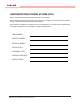
UNINTERRUPTIBLE POWER SYSTEM (UPS) Please complete the following information and retain for your records. Unless otherwise specified, the warranty period for the UPS or UPS part is 12 months from the shipment date (see Toshiba International Corporation bill of lading). Unless otherwise specified, the warranty period for a UPS battery is 36 months from the shipment date (see Toshiba International Corporation Bill of Lading for shipping date).
Purpose This manual provides information on how to safely install and operate your Toshiba International Corporation power electronics product. This manual includes a section of general safety instructions that describes the warning labels and symbols that are used throughout the manual. Read the manual completely before installing, operating, or performing maintenance on this equipment.
Table of Contents 1 Introduction...........................................................................................................................1 2 General Safety Instructions.................................................................................................2 2.1 Symbols........................................................................................................................2 2.2 Signal Words........................................................................
12 13 14 15 ii 11.4 External Breakers........................................................................................................36 11.5 Grounding Wire...........................................................................................................36 11.6 Control Wires..............................................................................................................38 11.7 Grounding Configuration....................................................................
1 Introduction This manual provides information on how to safely operate your G8000 Series Uninterruptible Power System (UPS). This manual includes a section of general safety instructions that describes the warning labels and symbols that are used throughout the manual. Read the manual completely before installing, operating, or performing maintenance on this equipment. Qualified personnel should read this manual carefully before transporting, installing and wiring the UPS.
2 General Safety Instructions DO NOT attempt to transport, install, operate, maintain or dispose of this equipment until you have read and understood all of the product safety information provided in this manual. 2.1 Symbols The symbols listed below are used throughout this manual. When symbols are used in this manual they will include important safety information that must be carefully followed. Safety Alert Symbol indicates that a potential personal injury hazard exists.
2.2 Signal Words The signal words listed below are used throughout this manual. When the words DANGER, WARNING, CAUTION and ATTENTION are used in this manual they will include important safety information that must be carefully followed. DANGER warning caution caution attention 2.3 The word DANGER in capital letters preceded by the safety alert symbol indicates that an imminently hazardous situation exists, if not avoided, will result in death or serious injury to personnel.
• Be trained in rendering first aid. For further information on workplace safety visit www.osha.gov. 2.4 Factory Authorized Personnel Factory authorized personnel have been factory trained and certified to install, service, and repair the UPS. Contact the Toshiba Customer Support Center for assistance in locating the factory authorized personnel nearest you.
4 Safety Precautions The Toshiba products listed in this document are intended for usage in general electronics applications (computer, personal equipment, office equipment, measuring equipment, industrial robotics, domestic appliances, etc.). These Toshiba products are neither intended nor warranted for use in equipment that, if a malfunction or failure occurs, may result in loss of human life or bodily injury (collectively referred to as “Unintended Usage”).
4.2 General Maintenance warning DO NOT remove the rear/side panels, or any sheet metla not designed to be removed. Removing rear/side panels may result in electric shock, burns, personal injuries or UPS failure. Keep the area arround the UPS clean. Use a vacuum cleaner to clean the UPS. Only factory authorized personnel sould perform internal general maintenance on the UPS.
caution DO NOT transport, move, store, or place the UPS on its side. Forces due to heavy components inside may damage the UPS. Avoid vibration or shock exceeding 0.5G. Failing to observe this precaution may cause damage to the UPS. DO NOT allow the UPS to suffer shock or impact when unpacking. Tools used to remove packaging materials may cause damage to the UPS. DO NOT push or pull on the sides of the packaging.or the UPS to move it.
4.4 Inspection/Storage Inspection Upon receipt of the UPS, an inspection for shipping damage should be performed. Use caution when removing the unit from the pallet. Refer to labels or documentation attached to packing material. Unpacking Check the unit for loose, broken, bent or otherwise damaged parts. If damage has occurred during shipping, keep all original crating and packing materials for return to the shipping agent.
5 Installation Precautions caution Install the UPS in a controlled environment. Improper storage and installation environment may deteriorate insulation, shorten component life and cause malfunctions. See Table 5.1 - UPS Installation Environment Standards DO NOT tilt the UPS more than 10° from upright position. Tilting the UPS more than 10° may cause crushing, trapping or other personal injuries and cause physical damage to internal components. warning Keep the SPECIFIED CLEARANCE around the UPS.
DO NOT block air vents. Blocking the vents will increase the internal temperatures and may result in UPS failure or fire. DO NOT install the UPS where water may fall on it. Water may cause electrical shock, personal injury or UPS failure. DO NOT use floor wax that contains silicon in the UPS storage area and/or nearby rooms. Floor wax that contains silicon may cause static electricity. warning The UPS should be installed per local and/or national electric codes by qualified personnel.
TABLE 5.1 - UPS INSTALLATION ENVIRONMENT STANDARDS Item Environment standard Installation Location Indoors Minimum operating temperature: 32 °F (0 °C). Maximum operating temperature: 86 °F (30 °C) at 1.0 PF (UPS with/without battery system). Ambient Temperature Maximum operating temperature: 90 °F (32 °C) at 0.8 PF (UPS with battery system). Maximum operating temperature: 104 °F (40 °C) at 0.8 PF (UPS only). Average 24-hour operating temperature: 86 °F (30 °C) at 1.0 PF and 41 – 95 °F (5 – 35 °C) at 0.
7) The UPS generates and can radiate radio-frequency energy during operation. Although RFI noise filters are installed inside of the unit, there is no guarantee that the UPS will not influence some sensitive devices that are operating near by. If such interference is experienced, the UPS should be installed further away from the affected equipment and/or powered from a different source than that of the installed equipment.
5.1 Wiring/Connection WARNING Perform wiring and connections with correct polarity. Be careful when connecting the UPS to the battery system. A wrong connection may cause damage to the UPS, battery, or charger. Connect ONLY one (1) ground wire to the earth ground terminal. A missing ground wire may cause an electrical shock hazard. Connecting to more than one ground may cause a ground loop. See Chapter 8 - UPS Wiring DO NOT force, bend, or pull wires. DO NOT damage wire insulation.
6 Warning Labels Below are representative warning labels and their location on the UPS. Exterior Handling labels shown in section 4.3, Transporting/Unpacking, are in the manual packet, and attached to the UPS shipping covering and shipping pallet. ATTENTION Make sure all the warning labels are installed in the appropriate locations. If a label is missing or illegible, contact Toshiba Customer Support Center or an authorized representative.
(D) 40830 (C) 58708 FOR 300KVA USE COPPER CONDUCTORS ONLY ! REFER TO INSTRUCTION MANUAL FOR WIRE SIZE AND TIGHTENING TORQUE 1 58708 U 2 3 4 V W - 5 6 7 + U V 8 9 10 W N U 11 12 V W 480 V 400 V 480 V 480 V A C INPUT BATTERY BYPASS INPUT AC OUTPUT WA R N I N G CRITICAL FUSE SIZING Incorrect fuse replacement size may result in fire or inadequate equipment protection. Replace only with same type and rating of fuse.
FIGURE 6.3 – 150/225 kVA UPS WARNING LABELS FIGURE 6.
7 Weight and Dimensions Table 7.1 lists the unit and shipping weights for G8000 UPS models illustrated in Figures 7.1 – 7.3. TABLE 7.1 G8000 UPS UNIT AND SHIPPING WEIGHTS Model Unit Shipping 100 kVA 1740 lb. (789 kg) 1790 lb. (812 kg) 150 kVA 2467 lb. (1119 kg) 2556 lb. (1159 kg) 225 kVA 2980 lb. (1352 kg) 3069 lb. (1392 kg) 300 kVA 4575 lb. (2075 kg) 4725 lb. (2143 kg) “8A” Switch TerminaL BloCKs Ground bus FIGURE 7.
79.2 “8A” Switch TerminaL BloCKs Ground bus FIGURE 7.2 - 150/225 kVA UPS EXTERIOR DIMENSIONS (INCHES) Ground bus TerminaL BloCKs 82.5 “8A” Switch FIGURE 7.
8 Transporting warning When transporting the UPS by crane, follow the SPECIFIED WORK PROCEDURE. The suspension wire angle should be less than 60°. The UPS falling or overturning may cause crushing, trapping or other personal injuries. DO NOT tilt the UPS more than 10° from upright position. Tilting the UPS more than 10° may cause crushing, trapping or other personal injuries. caution DO NOT transport, move, store, or place the UPS on its side.
8.1 8.1Transporting ByBy Crane Transporting Crane Cables should have sufficient ratings and be of the same length. Make sure the suspension cables are Cables should have sufficient ratings and the be angle of theless same Makecables. sure the suspension cables are hooked at eyebolts. See Figure 8.1. Keep thanlength. 60° between hooked at eyebolts. See Figure 8.1. Keep the angle less than 60° between cables. refer to Chapter 7 - Weight and Dimension for UpS cabinet weight.
8.2 Transporting By Forklift Refer to Chapter 7 - Weight and Dimensions. Verify forklift maximum load capacity and ensure that the forks are long enough to properly support the UPS. Insert the forks into the space shown in Figure 8.6. Spaces for the forks are provided underneath the UPS. DO NOT swing or tilt UPS when lifting and/or transporting. Minimize the impact when lowering the UPS to the floor.
9 Storage/Operating Environment Observe the following when storing the UPS. • • • • • • • • • Store UPS indoors. Maximum storage time for the UPS between powered operation cycles is three years. If the UPS has been stored for a period exceeding 36 months, contact your factory authorized represnetative of guidance in starting the unit. Temperature fluctuations should be minimized. The optimal storage temperature range is 68 – 77 °F (20 – 25° C).
3) The UPS should not be used with a load that has a rated input that is greater than the rated output of the UPS. 4) If using the UPS to provide power to motors that require high starting current or with motors that require a long starting time, call Toshiba support for guidance in over sizing the UPS for lock rotor current. 5) DO NOT insert metal objects or combustible materials in the ventilation slots of the UPS. 6) DO NOT place, hang, or paste any objects on the exterior surfaces of the UPS.
9.2 Maintenance Precautions All internal maintenance sould be performed by factory authorized personnel. 1) Turn off, lockout, and tagout ALL power sources before connecting the power wiring to the equipment or when performing maintenance. 2) Hardwire type UPS units are not equipped with an over-current protection device, nor do they have an output disconnect for the AC output. A user-installed circuit breaker should be provided between the UPS output and the load input.
Caution DO NOT dispose of the batteries in a fire. The batteries may explode. DO NOT open or mutilate the batteries. Released electrolyte is harmful to the eyes and skin and could also be toxic. danger A battery can present a risk of electrical shock and high short circuit current. 9.3 Disposal Please contact your local or state environmental agency for details on disposal of electrical components and packaging in your particular area.
10 Installation warning Keep the SPECIFIED CLEARANCE around the UPS. Inadequate space around the UPS makes it difficult to perform maintenance/inspections, lead to insufficient ventilation, and/or will cause malfunctions. See Figure 10.1 - UPS Clearance DO NOT tilt the UPS more than 10° from upright position. Tilting the UPS more than 10° may cause crushing, trapping or other personal injuries. Install anchor bolts to secure the UPS to the installation floor.
10.1 Unpacking Unpack the UPS indoors on a paved floor. The UPS should be as close as possible to its final storage location. Overhead traveling cranes should be used to unpack any G8000 Series UPS. If an overhead traveling crane is not available, allow enough space for forklift operations to unpack the UPS crate. Then remove the crate. Points to observe 10.2 • Retain all small articles during unpacking and installation.
10.3 Anchor Bolts 10.3 Anchor Bolts Install the anchor bolts to secure the UpS on the floor. See Figure 10.2 for anchor bolt installation detail. Install the anchor bolts to secure UPSThere on the floor. See(5/8”) Figure 10.2 forholes anchor bolt installation detail. Use 12mm (1/2”) diameter anchorthe bolts. are 16mm diameter provided in the UpS base. Use 12mm (1/2”) diameter anchor bolts. There are 16mm (5/8”) diameter holes provided in the UPS base. See Figure 10.
11 UPS Wiring 11FigureUPS Wiring 11.1 illustrates the external wiring of the G8000 UpS. See corresponding section to each wiring term. Note: Always consult your local and NEC electrical codes for wiring, cabling, and circuit protection device requirements. power cable connection at terminal blocks/buses and external breaker provision for the AC input/output, bypass Input and DC input. Figure 11.1 illustrates the external wiring of the G8000 UPS.
11.1 100 kVA Terminal Blocks and Power Cables 11.1 Terminal Power Cables Note: Always consultBlocks your site and specific, local, state, and NEC electrical codes for wiring, cabling, and circuit protection device requirements. The terminal blocks for the 100/150/225kVA UpS are shown in Figure 11.2. The terminal blocks are The terminal blocks the 100 kVAUpS. UPS are shown in Figure 11.2.
11.2 150, 225, and 300 kVA Buss Strip Terminals and Power Cables Note: Always consult your site specific, local, state, and NEC electrical codes for wiring, cabling, and circuit protection device requirements. The 150, 225, and 300 kVA UPS units have buss strip power terminals. Figure 11.3 is a typical buss strip for a 150/225 kVA UPS. 1.75 in. (45 mm) 3 in. (77 mm) 0.5 in. Dia. (1.27 mm) 1.97 in. (50 mm) 1.77 in. (45 mm) 5.3 in. (135 mm) FIGURE 11.3 - TERMINAL BUS Detail Figure 11.
For UPS’ equipped with buss strip terminals for the A/C INPUT, BYPASS INPUT, A/C OUTPUT and BATTERY connections, Toshiba recommends using the compression lugs listed in Table 11.2, or their equivalent, for cable terminations to be mounted on the bus strips. See Table 11.3 – Table 11.5 for recommended cable sizes for the 150, 225, and 300 kVA UPS. table 11.
table 11.4 Recommended cable size and fastener torque for 225 kVA unit Block Number Cable Size 1 Two AWG 2/0 or larger Recommended Fastener Torque ** 540 in.-lb. (6.2 kg-m) 2 Two AWG 2/0 or larger 540 in.-lb. (6.2 kg-m) 3 Two AWG 2/0 or larger 540 in.-lb. (6.2 kg-m) 4 Two AWG 2/0 or larger 540 in.-lb. (6.2 kg-m) 5 Two AWG 2/0 or larger 540 in.-lb. (6.2 kg-m) 6 Two AWG 2/0 or larger 540 in.-lb. (6.2 kg-m) 7 Two AWG 2/0 or larger 540 in.-lb. (6.2 kg-m) 8 Two AWG 2/0 or larger 540 in.
11.3 UPS Power Cable Knockout Plates The cable knockout plates are provided at the bottom of each 100/150/225kVA UpS. The recommended hole locations areplates illustrated in Figureat 11.3 and 11.4.of the 100 kVA UPS, and at the top and bottom of the Cable knockout are are provided bottom The cable knockout plates providedthe at the bottom of each 100/150/225kVA UpS. The recommended 150/225 kVA UPS. (Older models of 11.
Figure 11.6 shows the four (4) cable knockout plates provided at the top of the 300kVA UpS. Six (7) holes be the punched during The dashed rectangle indicates the kVA UpSUPS. opening behind Figure 11.9must shows four (4) cableinstallation. knockout plates provided at the top of the 300 Seven (7) the knockout plates. holes must be punched during installation. The dashed rectangle indicates the UPS opening behind the knockout plates. plate #1 plate #1 plate #4 plate #4 plate #2 2“ Dia.
11.4 External Breakers The G8000 UPS units are not equipped with circuit breakers. Qualified personnel should provide the external breakers for the AC input/output, bypass input and DC input. See Figure 11.1 – External Wiring Diagram, for the circuit position of the breakers. Table 11.6 shows the G8000 UPS minimum external breaker rating for each capacity. The bypass input and the AC output require 3-pole breakers. Table 11.6 EXTERNAL BREAKER RATING 11.
G8000 - 100 kVA Ground bus 10 mm or 7/16 in. Bolt 12 mm or 1/2 in. Terminal AWG 2 (38 mm) ground wire Feed-through opening To facility earth ground G8000 - 150/225 kVA Facility earth ground. Alternate ground wire routing through top knockout plate. Ground bus Note: Use either the top or the bottom access for the ground wire to connect to the ground buss, but use only one ground wire.. 10 mm or 7/16 in. Bolt 12 mm or 1/2 in.
11.6 Control Wires The control wires terminal layouts at TB1 (terminal bus 1) are shown below in Table 11.8. Table 11.8 EXTERNAL CONNECTIONS No.
The UPS battery cabinet and bypass breaker should be wired as shown below in Figure 11.11. Power Source Jumper wire if battery OH is not applied TC To Bypass Input Bypass Breaker 10 11 12 13 Power Source for trip coil 14 15 16 17 Overheat B-Contact 18 19 To DC Input 20 21 22 Auxillary Acontact TB1 UPS Cabinet Ext. EPO (Customer) N.O. Contacts Battery Cabinet FIGURE 11.
11.7 Grounding Configuration This section describes the grounding configuration to be used with various AC service entrance configurations. Inadequate grounding will cause problems at start-up. Connections for the ground line and the neutral line must be made appropriately according to the system configuration. 11.7.1 Recommended configuration (for 4 wire input with Input Neutral grounded) Figure 11.12 shows recommended grounding configuration when the input neutral is grounded.
Input Source 11.7.2 < UpS Cabinet > Grounding Configuration (without input neutral) 3Ǿ 3Ǿ When the input source is wye-connected, the neutral line out to the bypass input should be left open. The n n UPS is grounded by connecting the neutral terminal to the ground bus with the internal jumper cable. See 3Ǿ 3Ǿ 3Ǿ Figure 11.14. 3Ǿ To the load n The jumper cable should stay in place. See Figuren 11.13 for the jumper cable location.
remains in place Input Source < UpS Cabinet > 3Ǿ 11.7.4 3Ǿ n Grounding Configuration (with corner-grounded delta-input) 3Ǿ 3Ǿ 3Ǿ 3Ǿ n n To the If one phase of delta-input source is grounded (B-phase for example), the ground bus in the UPSload cabinet G G G G should NOT be connected to the neutral terminal of UPS output. Jumper Cable The jumper cable should be removed see Figure 11.13 for the remains jumperincable place location.
12 UPS Specifications 12.1 General Specification Specification Remarks UL1778-2001 UL, cUL Terms Conforming Standard Ambient Temperature PF = 1.0: 32 – 86 °F (0 – 30 °C) PF = 0.8: 86 – 104 °F (30 – 40 °C) Relative Humidity 30% – 90% Non-condensing < 3,280 ft. (< 1,000 m) Contact Toshiba Technical Support for installation above 3280 ft. (1000 m) 68 dB (100/150/225 kVA), 72 dB (300 kVA) 39 in. (1m) away from front 3 MΩ With 500V-Megger AC 2 kV – 1 min. Main Circuit AC 1.5 kV – 1 min.
12.2 Mechanical Specification (cont.) Nominal Capacity 150 kW 225 kW Cabinet Protection Conformity Exterior Paint 300 kW IEC298 IP20* Sherwin Williams, HHT2-7055, 079 Beige Texture FRONT: 1/16 in. (1.6 mm) BACK/SIDE/TOP: 3/64 in. (1.2 mm) BOTTOM: 1/8 in. (3.2 mm) Panel Thickness Input/Output Cabling Entrance TOP and BOTTOM TOP Ground/Control Wiring Entrance TOP and BOTTOM TOP W: 55.1 in. (1400 mm) D: 31.8 in. (808 mm) H: 79.2 in. (2012 mm) W: 76.8 in. (1951 mm) D: 31.8 in. (808 mm) H: 79.4 in.
12.3 Electrical Specification warning DO NOT open the front cover. Electric shock, burns or other personal injuries may occur if untrained personnel open the front cover. Nominal Capacity AC Input Rated Capacity* 100 kW 150 kW 225 kW 300 kW 110 kW (120 kW) 165 kW (180 kW) 245 kW (270 kW) 320 kW (320 kW) Input Voltage 480 V ( +10% to -15% ), 3-Phase 3-Wire Input Frequency 60 Hz ±5% Input Power Factor 0.95 – 1.
13 Operator Interface Table 13.1 shows the functions of the operating buttons on the graphic display panel. ATTENTION Press an operating button for at least 0.5 seconds to change UPS modes. Press the reset button for at least 5 seconds to reset the UPS. The UPS may not respond if the button press is too short. Table 13.1 Button AND indicator functions (See fig. 13.1 and 13.2) # Name Function 1 OPERATION LOCK Enables/disables the buttons RUN, STOP, UPS, BYPASS, FLOAT/EQUAL, and RESET.
13.1 Key-Switch and Buttons The key-switch and operating buttons on the graphic display panel are shown in Figure 13.1. See the sections titled “Key-switch” and “Operating buttons” for each function. 5 6 1 2 3 4 9 7 8 EPO 10 FIGURE 13.
13.2 LCD/LED Indicators 11 20 12 21 13 14 22 23 15 16 24 17 25 19 18 FIGURE 13.
13.3 LCD Indicators The operator can scroll through the following LCD display screens using the scroll buttons. tABLE 13.1 - LCD display screens Name Description Normal Display Displays operational status, operational guidance, and measured data. Fault Display Displays detailed data when a fault occurs. Warning Display Displays detailed data when a warning occurs. NORMAL DISPLAY SCROLL UP FAULT DISPLAY SCROLL DOWN WARNIG DISPLAY FIGURE 13.
13.4 Normal Display The Normal Display screen indicates the UPS operational status and provides various screens: an operation guidance screens, mode screens and measured data screens. Table 13.2 shows these screens page by page and illustrates the UPS Normal Display operational status screens. TABLE 13.2 - NORMAL DISPLAY SCREEN EXAMPLES OPERATIONAL STATUS SCREENS BYPASS Shows the UPS status at the top and guidance message or measured data underneath.
TABLE 13.2 - CONTINUED MEASUREMENT SCREENS O/P CURRENT (PEAK) U V W 50[%] 50[%] 50[%] AC INPUT Shows the peak output current peak (%) for each phase. Peak value of output current RMS value for rated current x 1.41 x 100 [%] Shows the AC Input Voltage (line-to-line) and frequency. AC I/P-V 480[V] FREQ. 60.0[Hz] Shows the Bypass Input Voltage (line-to-line voltage) and frequency. BYPASS INPUT BYP I/P-V 480[V] FREQ. 60.
13.5 Fault Display The Fault Display screen displays the fault records until they are reset. The Warning Display screen displays the warning records until they are reset. The fault records will remain in the memory until the reset button is pressed for at least 5 seconds, even after the actual cause of the fault has been resolved. Note that the fault records are not deleted when the UPS is turned off.
13.6 LCD Scroll Scroll through the LCD display screens (see Figure 13.4), in sequence, using the “SCROLL UP” and “SCROLL DOWN” buttons on the graphic display panel. • SCROLL UP - Moves back to the previous screen • SCROLL DOWN - Moves forward to the next screen TABLE 13.4 display screen scroll sequence UPS SUPPLY FAULTS & WARNINGS AC-VO 480[V] AC- I O 50[%] NO FAULT NO WARNING OPERATION MODE NORMAL OPERATION MODE SYNC. (The LCD displays a diagram of the electrical power flow.
14 Operating the UPS This section describes the basic procedures to operate the UPS. Figure 14.1 shows the location and functions of the operating switches to operate the UPS. WARNING If the UPS produces smoke or smells strange, immediately turn off all AC and DC input circuit breakers. Continued operation may result in fire. Contact Toshiba or Authorized representatives. DO NOT turn off the control power supply switch (8A) during UPS operation. This may result in UPS faults.
14.1 Operation Types The operation types are summarized below. TABLE 14.1 OPERATION TYPES 14.2 Operation Description Complete Shutdown Turn off the control power supply. Shut down the UPS completely. Float / Equalize Charge Changing the battery recharge mode between float charge and equalize charge. Protection Charge Automatic recharge mode transition from protection charge to float charge. Startup Starting up and operating the UPS. Stop Stop the inverter and chopper/charger.
14.3 Startup Procedures The procedure to start the UPS is shown in Steps 1-5. STEP 1 LED Key - LED Off - LED On - LED Flash SYSTEM INITIALIZE Turn on the control power supply switch. (Figure 14.1) and ensure the operation lock is set to OPERATION. (Figure 13.1 - 1) UPS AC INPUT CONVERTER INVERTER FLOAT CHARGE AC SWITCH EQUAL CHARGE BATTERIES DISCHARGE AC OUTPUT BYPASS BYPASS INPUT STEP 2 BYPASS Wait for a few seconds.
Step 4-5 continues the procedure to start the UPS. LED Key - LED Off - LED On - LED Flash STEP 4 BYPASS Turn on the DC Input Breaker (72B) on the external battery cabinet. MOVE 72B TO ‘ON’ POSITION BATTERIES LED is “ON”. UPS AC INPUT INVERTER CONVERTER FLOAT CHARGE AC SWITCH EQUAL CHARGE BATTERIES DISCHARGE AC OUTPUT BYPASS BYPASS INPUT UPS SUPPLY STEP 5 AC - Vo 480 V AC - Io 50% *Press the “UPS” button for at least 0.5 seconds. This completes UPS startup procedure BYPASS LED is “OFF”.
14.4 Switch Power Supply (UPS→Bypass) The procedure to transfer between the UPS supply and the bypass supply is shown in Steps 1-3 LED Key - LED Off - LED On - LED Flash STEP 1 UPS SUPPLY Check AC INPUT LED and BYPASS LED are on to make sure power is being delivered to the UPS. AC - Vo 480 v AC - Io 50% UPS AC INPUT CONVERTER INVERTER FLOAT CHARGE AC SWITCH EQUAL CHARGE BATTERIES DISCHARGE BYPASS BYPASS INPUT STEP 2 AC OUTPUT BYPASS Press the “BYPASS” button for at least 0.5 seconds.
14.5 Stop The procedure to stop the UPS is shown in Steps 1-3. LED Key - LED Off - LED On - LED Flash BYPASS STEP 1 AC - Vo 480 V AC - Io 50% PRESS ‘UPS’ SWITCH Transfer to Bypass supply as described in Switch Power Supply. UPS LED is “OFF”. BYPASS LED is “ON”.
14.6 Complete Shutdown The procedure to turn off the control power and shut down the UPS completely is shown in Steps 1-6. STEP 1 Transfer to Bypass supply as described in Switch Power Supply. UPS LED is “OFF”. BYPASS LED is “ON”. BYPASS DC-V 0 [V] BATT-V 0 [V] BATT-I 0 [A] STEP 2 Turn off the DC input breaker, and, press the “STOP” button for at least 0.5 sec. BATTERIES LED is “OFF”. INVERTER LED flashes then “OFF”. FLOAT CHARGE LED and CONVERTER LED are “OFF”.
14.7 Changing Between Float Charge and Equalize Charge The procedure to change the recharge mode between float charge and equalize charge is shown in Steps 1-3. See the Note below for an explanation of Float and Equalize charge modes. LED Key - LED Off - LED On - LED Flash STEP 1 UPS SUPPLY Make sure that the FLOAT CHARGE LED is “ON”.
14.8 Changing to Float Charge from Protection Charge (If applicable) The manual procedure to change from protection charge to float charge is shown in Step 1-3.This operation applies to batteries after they have experienced over temperature condition. See the Note below for an explanation of float charge and protection charge. STEP 1 LED Key - LED Off - LED On - LED Flash UPS SUPPLY Make sure that the EQUAL CHARGE LED is “ON”.
14.9 Emergency Power Off (EPO) Press the EPO switch for immediate shutdown of all power through the UPS. The signal from the EPO is processed as a “hard fault” by the UPS and results in gate-blocks on the transistors and opens all the internal contactors. To Reset the UPS after triggering the EPO, do the following: 1. Shut Down the UPS as described in section 14.6. 2. Restart the UPS as described in section 14.3.
15.2 Faults and Warnings Data Screen This screen appears when a trip error is detected. Up to 10 screens of fault data can be displayed. Figure 15.1 and Table 15.2 show a sample screen and describe the data shown in the screen. FAULTS & WARNINGS 1 UPS OVERLOAD 09-09-06 08:05:30 ↓ANOTHER ITEM 1 2 3 4 FIGURE 15.1 - SAMPLE FAULT DATA SCREEN TABLE 15.2 - FAULT AND WARNING DATA SCREEN DESCRIPTIONS # Name Description 1 Number The number of the message in the order that it was detected (1 - 10).
15.3 LCD Fault & Warning Displays When a fault occurs, a screen is shown as in Figure 15.2. When a warning occurs, a screen is shown as in Figure 15.3. Select the desired fault or warning data to be displayed using the scroll buttons. BYPASS FAULT STOP FAULTS & WARNINGS 1 FUSE BLOWN 09-09-06 08:05:30 FIGURE 15.2 - fault DISPLAY UPS SUPPLY AC-VO 480[V] AC- I O 50[%] FAULTS & WARNINGS 1 UPS OVERLOAD 09-09-06 08:05:30 FIGURE 15.
15.4 Fault Messages Figure 15.4 show the locations for fault detection. Tables 15.3 through 15.7 gives details for the fault and warning messages referred to in section “Fault Data Screen.” The “item” code associated with each fault or warning message may be used to determine the physical location of the fault or warning by referring to Figure 15.4. The UPS unit may be shipped with different protective configurations from the standard shown in Figure 15.4, if specified by the customer.
TABLE 15.5 - WARNING - 2 (STOP AND RESTART) Item LCD Message Indication Description 27I AC O/P UV AC output voltage is low. 30U UNIT FAULT IGBT Stack Failure. 45 DC OV Over-voltage in DC circuit. 49 AC O/P OL Output overload 51I INV. OC Inverter over-current. 59I AC O/P OV AC output voltage is high. 76C BATT. OC Over-current in Battery section. TABLE 15.6 - WARNING (OPERATION CONTROL) Item LCD Message Indication Description 27C BYPASS UV Bypass input voltage is low.
15.5 LCD Scroll (w/ faults or warnings) This section describes how to scroll through the LCD screens when a fault has occurred (when Fault Data screens exist). Figure 15.5 shows the locations of the buttons to scroll the LCD screens. See Table 15.8 for details of the scroll buttons and how they are used for screen scrolling. 5 6 7 FIGURE 15.5 - POSITION OF SCROLL AND RESET BUTTONS Table 15.8 - Button functions # Name Function 5 SCROLL UP Scrolls to the previous screen.
15.6 Restoring UPS Operation WARNING Contact Toshiba in the event of malfunction or fault. This UPS should be repaired only by factory authorized personnel. Servicing by untrained personnel may extend the fault or result in electric shock or personal injury. Do NOT attempt to modify or relocate the UPS. Electric shock, personal injury or fault may result if unauthorized personnel attempt to modify or relocate the UPS. Be sure to contact toshiba customer service if you need to modify or relocate the UPS.
INDUSTRIAL DIVISION 13131 West Little Your road, Houston, Texas 77041 Tel (713) 466-0277 Fax (713) 466-8773 U.S. (877) 867-8773 Canada (800) 872-2192 Mexico 01/800/527-1204 www.toshiba.com/ind Printed in the U.S.A.