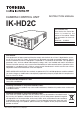
CAMERA CONTROL UNIT INSTRUCTION MANUAL IK-HD2C For Customer Use Enter below the Serial No. which is located on the bottom of the cabinet. Retain this information for future reference. Model No.: IK-HD2C Serial No.: FCC NOTICE This equipment has been tested and found to comply with the limits for a Class A digital device, pursuant to Part 15 of the FCC Rules. These limits are designed to provide reasonable protection against harmful interference when the equipment is operated in a commercial environment.
SAFETY PRECAUTIONS Safety icons This manual contains safety instructions that must be observed in order to avoid potential hazards that could result in personal injuries, damage to your equipment, or loss of data. These safety cautions have been classified according to the seriousness of the risk, and the icons highlight these instructions as follows: Indicates a potentially hazardous situation which, if not avoided, could result in death or serious injury.
Note the following instructions when installing. 5 Do not cover the product with any material. 5 Do not place the product on any inflammable material such as a carpet or blanket. 5 o not place the product in a confined space, as this may cause heat to build up inside the product. Failure to follow the above cautions may result in fire. Do not place the product in direct sunshine and/or high temperature. Temperature build up inside the product may result in fire.
Limitation of Usage The product is not designed for any “critical applications.” “Critical applications” means life support systems, exhaust or smoke extraction applications, medical applications, commercial aviation, mass transit applications, military applications, homeland security applications, nuclear facilities or systems or any other applications where product failure could lead to injury to persons or less of life or catastrophic property damage.
(6) SYNC........................................................................................................................... (6.1) INT screen........................................................................................................... (6.2) Changing EXT. setting ........................................................................................ (7) OPTION....................................................................................................................... (7.
1. CAUTIONS ON USE AND INSTALLATION " Handling the unit. The following descriptions are for a camera head "IK-HD1H" connected to this camera control unit. Do not drop, jolt, or vibrate, as this may result in damage to the unit and cause problems. Treat the camera cables carefully to prevent cable problems, such as breaks in the cable and loose connections. " " If there is an intense light at a location on the screen such as a spot light, a blooming and smearing may occur.
3 ITEMS CONTROLLED BY THE ON SCREEN DISPLAY 㻬㼗㼈㼐 㻤㼙㼄㼌㼏㼄㼅㼏㼈㻃㼖㼈㼏㼈㼆㼗㼌㼒㼑㼖 AUTO, MANUAL, SS -100 – 0 – 100 00 : 10 – 05 : 05 – 10 : 00 1 – 10 – 20 PRESET A, PRESET B, PRESET C, PRESET D, AUTO area PRESET E, USER (USER area is possible to set in 64 zones) OFF, 1/100s, 1/125s, 1/250s, 1/500s, 1/1000s, MANUAL speed 1/3000s, 1/5000s, 1/10000s, 1/30000s, 1/50000s Syncro.
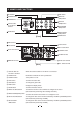
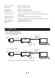
4. NAMES AND FUNCTIONS FILE button DISP button POWER switch MENU UP (SHD) button POWER LED DATA UP (AWB) button Camera cable for “IK-HD1H” terminal DATA DOWN (ABB) button GAIN button MENU DOWN (SHD) button PAGE button [Front] PB/B terminal PR/R terminal Y/G terminal KEY LOCK switch 60I DC IN 12V terminal 1 2 4 3 FORMAT switch HD-SDI terminal 1 2 3 4 5 6 7 8 9 SYNC OUT terminal REMOTE terminal EXT.
䐡 DC IN 12V terminal Accept a DC power input (12V). 䐢 Y/G terminal Outputs Y or G. (BNC connector) 䐣 PB/B terminal Outputs PB or B. (BNC connector) 䐤 PR/R terminal Outputs PR or R. (BNC connector) 䐥 REMOTE terminal To connect to a RS-232C device for remote control function. 䐦 EXT. SYNC terminal Used when the camera output signal is synchronized to an external signal. (BNC connector) 䐧 SYNC OUT terminal Output terminal for synchronization signal.
5 2 Caution on Connection 䝿 Only use optional camera head model # IK-HD1H with this camera controller. The use of another head may cause damage to the control unit and camera head. 䝿 When connecting the camera cables, be sure to turn off the camera control unit and any other equipment connected to it. 䝿 For DC power supply connecting to DC IN 12V terminal, use UL listed and/or CSA approved ungrounded type AC adaptor with the specifications described below.
6 OPERATION A camera head "IK-HD1H" needs to be connected to this camera control unit from this section on. 䐖 Refer to the item “5. CONNECTION”, connect the equipment correctly. 䐗 Turn on the connected equipment and the camera. 䐘 When using the camera for the first time and when replacing the camera cable and the camera head, be sure to perform the ABB adjustment, refer to the item “6.1 Automatic Black Balance”. 䐙 Aim the lens at the object, adjust the lens iris adjustment, focus adjustment, etc.
6 2 White Balance For white balance adjustment of this unit, ATW (Automatic Tracking White balance), AWB (Automatic White Balance) and MANUAL (Manual white balance) adjustments are provided. Refer to the items “7.2 (3) WHT BAL (White Balance), 7. MODE SETTING BY THE ON SCREEN DISPLAY”, select the desired mode. Outline Features Notes ATW 䟺 Automatic Tracking White Balance䟻 䟻 The camera measures the object color temperature and adjusts the white balance automatically.
Display Meaning AWB OK Automatic white balance adjustment finished correctly. AWB NG Automatic white balance adjustment cannot be performed because the video level is too low. Adjust the video level by increasing the illumination or opening the lens iris. LEVEL LOW AWB NG LEVEL HIGH AWB NG C. TEMP LOW Automatic white balance adjustment cannot be performed because the video level is too high. Adjust the video level by decreasing the illumination or closing the lens iris.
6 3 Scene File .:* 7(*3* +.1*7 &6* &:&.1&'1* &7 97*6 2*246.*7 +46 8-.7 93.8 -*7* &6* (-47*3 )*5*3).3, 43 7-448.3, (43).8.437 = 97.3, 8-* $ % '98843 8-* (&2*6& 45*6&8.43 .7 (-&3,*) .22*).&8*1= +642 8-* (966*381= 7*1*(8*) (*3* .1* 84 8-* 3*<8 *+*6 84 8-* .8*2 > # #? 䝿 "-.1* &3= 2*39 .7 ).751&=*) 56*77.3, 8-* $ % '98843 ;.11 ).751&= 8-* 2*39 7*88.3,7 +46 8-* 3*<8 (*3* .
Note: White, red, green, or blue dots may occur when the gain is increased. This is not a malfunction, just certain characteristics of the CCD becoming more visible. 6 5 Shading Correction Due to the lens used or the environmental condition, color shading may occur at the upper and lower edge of the screen. If this happens, the shading correction function can be used to decrease the amount of color shading.
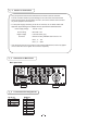
7 MODE SETTING BY THE ON SCREEN DISPLAY Various settings can be controlled on the unit by using the on screen menu displayed on the monitor. The contents once set are memorized in the scene files (A, B, C, D, E) selected, so if the power turns off, it is unnecessary to set again when using the unit next time. When the setting is performed, select the menu of the item to be set. 7 1 Using the Menus When the power turns on, the normal screen showing only the video signal appears.
7 2 Menus 䝿 Select the menu to change the setting by referring to the item “7.1 Using the Menus”. 䝿 When the [MENU UP], [MENU DOWN] buttons are pushed, the “䊲” on the screen moves up and down. Move the “䊲” to the item whose setting you wish to change. 1 SHUTTER䟺Electronic shutter䟻 The electronic shutter has four modes; AUTO, MANUAL, SS(Synchro. Scan). Press the “Page” button to enter the Shutter Page. Use the “Data Up/Down” buttons to select the Shutter Mode.
䟺1䠀 䠀1䟻 䟻 Changing the setting in AUTO mode Move up and down by pushing MENU UP,DOWN Select the desired value by pushing DATA UP,DOWN Shutter mode AUTO, MANUAL, SS Video level adjustment -- 1 SHUTTER -- -100 to 100 Peak and average ratio adjustment MODE LEVEL PEAK AVE SPEED AREA AREA DISPLAY AUTO 0 05 05 10 PRESET A OFF 00 10 to 10 00 Automatic shutter response speed adjustment 1 to 20 Automatic shutter area selection PRESET A, PRESET B, PRESET C, PRESET D, PRESET E, USER Automatic sh
(d) Changing the automatic shutter zone area 䐖 Move the “䊲” to AREA by pushing [MENU UP], [MENU DOWN] buttons. 䐗 Select the measurement light area by pushing [DATA UP], [DATA DOWN] buttons. 䠭DATA UP䠯 PRESET A PRESET B PRESET C PRESET D 䠭DATA DOWN䠯 PRESET E USER The available picture area is shown by the shading correction on the screen that is parted in 64.
䟺1䠀 䠀2䟻 䟻 Changing the setting in MANUAL mode Move up and down by pushing MENU UP,DOWN Select the desired value by pushing DATA UP,DOWN Shutter mode -- 1 SHUTTER -- MODE MANUAL AUTO, MANUAL, SS Shutter speed setting OFF, 1/100s, 1/125s, 1/250s, 1/500s, 1/1000s, 1/3000s, 1/5000s, 1/10000s, 1/30000s, 1/50000s MANUAL 1 10000s < MODE = MANUAL> (a) Changing the shutter speed 䐖 Move the “䊲” to MANU by pushing [MENU UP], [MENU DOWN] buttons.
2 GAIN (Video gain) GAIN has three modes; AUTO, MANUAL, OFF. Move the “䊲 ” to MODE, push the [DATA UP], [DATA DOWN], and select one of the three modes : AUTO, MANUAL, OFF. In the OFF mode, gain is fixed to 0dB.
䟺3䟻 䟻 WHT BAL(White Balance) The WHT BAL has three modes; AWB, ATW, MANUAL. Move the “ 䊲” to MODE, push the [DATA UP], [DATA DOWN], and select one of the three modes : AWB, ATW, MANUAL.
The available picture area is shown by the shading correction on the screen that is divided into 64 parts. PRESET A PRESET B PRESET C PRESET D Custom Selection USER PRESET E (e) Confirming the contents of the zone area selected by AWB 䐖 Set the “䊲” to AREA DISP by pushing [MENU UP], [MENU DOWN] buttons. 䐗 Area screen appears by pushing [DATA UP], [DATA DOWN] buttons. When AREA is set to USER, the setting can be changed on the area menu. When changing the area, refer to the item “7.
(b) Changing B PAINT 䐖 Move the “䊲” to B PAINT by pushing [MENU UP], [MENU DOWN] buttons. 䐗 Select the desired value of blue paint by pushing [DATA UP], [DATA DOWN] buttons. 䠭DATA UP䠯 䟿10 Blue is increased. 0 10 䠭DATA DOWN䠯 Blue is decreased.
䟺4䟻 䟻 PROCESS Move up and down by pushing MENU UP,DOWN Select the desired value by pushing DATA UP,DOWN Gamma correction -- 4 PROCESS -- GAMMA ON/OFF GAMMA DTL GAIN M PED R PED B PED DNR ON, OFF Gamma correction level setting Detail gain setting ON 0 0 0 0 0 OFF -10 to 10 -7 to 7 Master pedestal setting -200 to 200 Red pedestal setting -100 to 100 Blue pedestal setting -100 to 100 Digital noise reduction ON,OFF 䟺4䠀 䠀1䟻 䟻 Changing gamma correction ON/OFF 䐖 Move the “䊲” to GAMMA
䟺4䠀 䠀3䟻 䟻 Changing black gamma correction level 䐖 % % )2* %! + ,. ( "&$ &%%! $ 䐗 % 0 11 !## % ! ( "&$ &%%! $ 䠭 䠯 / 䠭 䠯 - * When OFF is selected in GAMMA ON/OFF selection line, the display BLACK GAMMA turns off automatically. So the black gamma correction level change cannot be changed.
䟺5䟻 䟻 MATRIX(Matrix color correction) Move up and down by pushing MENU UP,DOWN Red hue setting -- 5 MATRIX -- Red gain setting MATRIX ON Green hue setting R R G G B B 0 0 0 0 0 0 Green gain setting Blue hue setting Select the desired value by pushing DATA UP,DOWN HUE GAIN HUE GAIN HUE GAIN Matrix color correction ON, OFF Yellow hue setting Yellow gain setting Ye Ye Cy Cy Mg Mg HUE GAIN HUE GAIN HUE GAIN 0 0 0 0 0 0 Blue gain setting Cyan hue setting Cyan gain setting Magenta hue
䟺6䟻 䟻 SYNC When an external sync signal is input, the display changes from INT (internal sync) to EXT.(external sync) automatically. INT EXT 䟺6䠀 䠀1䟻 䟻 INT screen -- 6 SYNC -- MODE INT 䟺6䠀 䠀2䟻 䟻 Changing EXT.
䟺7䟻 䟻 OPTION Move up and down by pushing MENU UP,DOWN Select the desired value by pushing DATA UP,DOWN OUTPUT -- 7 OPTION -- Y/Pb/Pr, RGB SHADING MODE OUTPUT Y/Pb/Pr SHADING DTL OUT BAUD RATE OSD OUTPUT OFF OFF 9600bps ALL ON SET, MANUAL, OFF Detail signal output ON, OFF RS232C baud rate OSD OUTPUT 9600bps, 19200bps ALL ON, Analog, Digital 䟺7䠀 䠀1䟻 䟻 Changing OUTPUT mode 䐖 Move the “䊲” to OUTPUT by pushing [MENU UP], [MENU DOWN] buttons.
$* )% # $<# + %)' !# " ( ( '!& * ") + %)' !# / / & -- 7 OPTION -- OUTPUT RGB RGB SYNC SHADING DTL OUT BAUD RATE OSD OUTPUT G OFF OFF 9600bps ALL ON 8 9 ((!# 䟿126 ($ 125 ( !" '! # " $)(%)( 232 ) & ( 7400 %' 17200 %' # "$ ! !( " 䟺7䠀 䠀4䟻 䟻 Changing RGB SYNC 䐖 $* ( ,䊲- ($ + %)' !# )(($#' 䐗
䠄8䠅 䠅 Setting USER area 䡡 When USER is selected for the AREA of the automatic shutter or for AWB, the light measurement zones can be changed. 䡡 The USER area is composed of 64 zones with 8 (vertical) x 8 (horizontal) areas, and each area can be set to ON/OFF. 䐟 Set the output to area menu. Set the output to the area menu by referring to the item “7.2 (1.1) (e) Confirming the contents of the measurement light area selected by automatic shutter” and “7.2 (3.
䟺9䟻 䟻 Returning to factory settings The contents set of each scene file can be returned to the factory default status (preset status). (1) Select a scene file to set to the factory default status by pressing the [FILE] button. (2) If the color bar pattern or characters are displayed on the screen, press the [DISP] button to disable the color bar pattern and character display. (3) Push [MENU DOWN] and [DATA DOWN] buttons simultaneously for approx. 1 second. (4) The preset operation starts.
8.
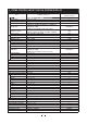
9. SPECIFICATIONS * These conditions are only satisfied when the camera control unit is connected to camera head model # IK-HD1H. Power supply Power consumption Image-acquisition method Image sensor Output pixels Scanning system Scan frequency Sync system Horizontal resolution Vertical resolution Sensitivity Minimum illumination SN ratio Ambient temperature Ambient humidity Weight External dimension Scene file(user memories) White balance Gain Output signal 12V DC㼳10% Approx. 10.
10.
Memo 36
Limited Warranty – TOSHIBA Camera Control Unit The Imaging Systems Division of Toshiba America Information Systems, Inc. ("ISD") makes the following limited warranty with regard to this Camera Control Unit ("Product"). These limited warranties apply to the Original End-User ("You"). One (1) Year Limited Warranty of Labor and Parts ISD warrants that this Product will perform in accordance with specifications for a period of one (1) year from the date of purchase by the Original End-User.