INSTRUCTION MANUAL CAMERA CONTROL UNIT IK-CU44A For Customer Use Enter below the Serial No. which is located on the bottom of the cabinet. Retain this information for future reference. Model No.: IK-CU44A Serial No.: INFORMATION This equipment has been tested and found to comply with the limits for a Class A digital device, pursuant to Part 15 of the FCC Rules.
SAFETY PRECAUTIONS Read the following safety precautions carefully before using this product. These instructions contain valuable information on safe and proper use that will prevent harm and damage to the operator and other persons. Make sure that you fully understand the following details (indications, graphic symbols) before proceeding to the remaining sections in this manual.
• Do not put the product in an unstable, slanting and/or vibrated place. Drop and/or fail of the product may cause injury. • Do not touch the power cord or other connection cables during a thunderstorm. This might cause electric shock. Caution • Note the following instructions when installing. • Do not put an inflammable material on the product. • Do not put the product on an Inflammable material such as carpet or blanket. • Do not block a vent hole.
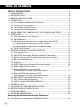
TABLE OF CONTENTS SAFETY PRECAUTIONS ................................................................................. 2 1. 2. 3. 4. 5. 6. 7. 8 9. 10. 11. 12. COMPONENTS ............................................................................................... 5 SPECIFICATIONS ........................................................................................... 5 NAMES AND FUNCTIONS ............................................................................ 6 CONNECTION .....................
1. COMPONENTS (1) Camera control unit .................................................................................. 1 (2) Accessories (a) Instruction manual ............................................................................. 1 2. SPECIFICATIONS Specification with camera head (IK-M44H) connected.
3.
1 CAMERA terminal 2 POWER switch 3 POWER indicator 4 AGC switch 5 WB switch 6 White balance adjust control Connects to the camera head. Turns on and off the camera control unit. Lights up when the power is turned on. Selects the gain mode. (AGC OFF/AGC ON/SENS UP) Selects the white balance mode. (MANU/SET/AUTO) Adjusts the R gain and B gain with the white balance mode set to MANU by the WB switch 5. 7 FUNC button Determines the setting indication contents when the setting menu is displayed on the screen.
4. CONNECTION 4.1 An Example of Standard Connection Monitor Camera control unit VIDEO Lens (Option) Camera head (Option) CAMERA DC IN 12V Camera cable (Option) DC 12V DC power supply 4.2 Cautions on Connection • When connecting or disconnecting the camera cables (for the camera head and camera control unit), always turn off the power switch of the camera control unit first. If not, the camera head may be damaged.
4.3 Connection on Back Panel The figure below shows the back panel connection terminals of the camera control unit. DC IN 12V 1 3 2 4 EXT SYNC S-VIDEO 4 3 2 1 VIDEO REMOTE IRIS FUNC LOCK 3 4 5 9 8 2 1 ON OFF 7 6 6 1 4 3 5 2 4.
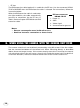
• EE lens The IRIS extension cable (optional) is usable for the EE lens. Use the connector HR10A7P-4P of HIROSE when the IRIS extension cable is selected. For connections, follow the instruction below. When the IRIS extension cable is used under the right condition, the cable automatically converts to connection for the EE lens in Table 1. See the Chapter OPTIONS for the IRIS extension cable. 1. 2. 3. 4.
6. OPERATION Turn on the POWER switch on the camera control unit and adjust the lens iris and focus while observing a picture on the monitor screen. To obtain the best picture quality, perform various settings. 6.1 AGC (Automatic Gain Control) AGC functions “OFF”, “ON” or “UP” can be selected on the screen menu. Generally, the camera is used with the AGC set to OFF, but when increased camera sensitivity is required, it is set to ON. When more sensitivity is required, “UP” is selected.
(1) White balance adjustment in modes other than AUTO (1.1) White balance adjustment in SET mode 1 Set the WB switch to “SET” position. 2 Shoot a white object to fill entire screen and press the UP button ( sec. , ) for about 2 3 When the white balance adjustment completes, the letters “WB SET” blinking at the upper right of the screen changes to “WB OK” and then turns off. If the “WB NG” is displayed, it shows the white balance is out of the adjustment range.
7. MODE SETTING BY ON SCREEN DISPLAY Setting while monitoring the menu on the monitor screen is possible. The following seven items can be set. 1 Scene file 2 Electronic shutter (AUTO/MANUAL), backlight correction 3 Pedestal level 4 Phase matching in external synchronization (horizontal/subcarrier synchronization) 5 White balance, auto electronic shutter, AGC measurement area 6 White balance offset 7 Scene file factory setting Press the FUNC button to display the menu.
7.1 FILE (Scene File) There are two scene files A and B which can be selected according to the shooting state. 1 Move the cursor to “FILE” in the main menu using the UP or DOWN button. FILE SHUTTER PEDESTAL SYNC AREA W B-OFFSET A AUTO 00 INT LINK:1 00 INIT. END 2 Press the FUNC button to display the contents to set FILE, A or B. Move the cursor to A or B using the UP or DOWN button. Press the FUNC button to set the contents. Note: • The scene file is for the menu screen.
(1) Detail setting in AUTO mode (auto electronic shutter) When the FUNC button is pressed after AUTO is selected, the submenu for SHUTTER:AUTO appears. Set details in this screen. LEVEL: BLC: PEAK:AVE: Adjust the auto electronic shutter video level. Larger values indicates brighter level, and vice versa. Data can be set in a range of –30 to +30. Correction for backlight. This can be set when the measurement area is set to one of “1/2”, “1/8” and “SLIT” for AREA in the main menu.
7.3 Pedestal 1 Move the cursor to PEDESTAL using the UP or DOWN button. 2 Press the FUNC button. The cursor moves to the data. Set the data using the UP or DOWN button. The data can be set in a range of –50 to +50. After setting the data, press the FUNC button to return to the main menu. FILE SHUTTER PEDESTAL SYNC AREA W B-OFFSET A AUTO 00 INT LINK:1 00 INIT. END PUSH FUNC TO SELECT FILE SHUTTER PEDESTAL SYNC AREA W B-OFFSET 00 INIT. END PUSH FUNC TO SELECT 7.
3 Move the cursor to a desired item (H-PHS, SCPHS, SC-FINE) using the UP or DOWN button. Press the FUNC button and the data is displayed. Set the data using the UP or DOWN button and press the FUNC button to select the data. To return to the main menu, move the cursor to EXIT and press the FUNC button. Note: • If the internal synchronization is set while the SYNC item (H-PHS, SC-PHS, SC-FINE) is being displayed, the display automatically turns to INT, disabling setting. 7.
2 Press the FUNC button to display data 1 ~ SLIT for LINK. Move the cursor to a desired item of AREA data (1, 1/2, 1/8, SLIT) using the UP or DOWN button. 3 Press the FUNC button to set the data. FILE SHUTTER PEDESTAL SYNC AREA W B-OFFSET INIT. END LINK 1 SEP 1/2 EXIT 1/8 SLIT PUSH FUNC TO SELECT (2) Setting AREA for white balance separately from the AREA setting for AGC and auto electronic shutter 1 Move the cursor to SEP using the UP or DOWN 2 3 4 5 button, and press the FUNC button.
7.6 WB-OFFSET (White Balance Offset) This offsets the white balance in the direction of orange or cyan when the WB switch is set to “SET”. 1 Move the cursor to WB-OFFSET using the UP or DOWN button. FILE SHUTTER PEDESTAL SYNC AREA W B-OFFSET A AUTO 00 INT LINK:1 00 INIT. END 2 Press the FUNC button. The cursor moves to the data item. 3 PUSH FUNC TO SELECT Change the data using the UP or DOWN button.
7.7 INIT. (Scene File Initialization) FILE SHUTTER PEDESTAL SYNC AREA W B-OFFSET This reset settings of the scene file to the factory setting. A AUTO 00 INT LINK:1 00 1 Select a scene file (A or B) to initialize the setting INIT. END in FILE. 2 Move the cursor to INIT. using the UP or DOWN button. PUSH FUNC TO SELECT 3 Press the FUNC button. The selected scene file (A or B) is displayed. NO/YES is displayed. 4 Select NO when not initializing. Select YES and press the FUNC button when initializing.
8. EXTERNAL SYNC When using the camera with external sync, connect a composite video signal (C-VIDEO) to the EXT SYNC terminal on back of the camera control unit. When the camera accepts external sync, it is automatically switched from the internal sync to the external sync. (1) External sync signal input conditions C-VIDEO (75Ω unbalanced) : SYNC section 0.3 ± 0.1V BURST section 0.3 ± 0.1V (2) External sync frequency range Within ±50 ppm in reference to NTSC standard frequency (H frequency 15733.
9. CAUTIONS ON USE AND INSTALLATION ● Carefully handle the units. Do not drop, or give a strong shock or vibration to the camera. This may cause problems. Treat the camera cables carefully to prevent cable problems, such as cable breakdown and loosened connections. ● Do not shoot intense light. If there is an intense light at a location on the screen such as a spot light, a blooming and smearing may occur. When intense light enters, vertical stripes may appear on the screen. This is not a malfunction.
10.
12. EXTERIOR DIMENSIONS Unit : mm [inch] Camera Control Unit 156 [6.14] 85 [3.35] 11 [0.43] AGC 21.5 [0.85] EXT SYNC 21.5 [0.85] S-VIDEO IRIS ON OFF 24.5 [0.96] 24 [0.94] 19 [0.75] 4-M3 pitch 0.5 Threaded hole 3.9 [0.15] 24 114 [4.49] VIDEO REMOTE FUNC LOCK 27 [1.06] 26.5 [1.04] 10 [0.39] φ12 [0.47] FUNC B 63 [2.48] 20 [0.79] WB SET 9 [0.35] R DC IN 12V WB AUTO SET MANU UP ON OFF 3.9 [0.15] 10.5 [0.41] 28 [1.10] POWER ON OFF 20 [0.79] 40 [1.57] CAMERA 7 [0.28] 10.
Servicing Instructions for Service Personnel 13. Connection to Camera Head (IK-M43H/IK-C43H) When connecting to the camera head (IK-M43H/IK-C43H), select the internal switch inside the camera controller following to the procedures below. (2) 1 After turning off the power, remove all the cables connected to the camera controller. (1) 2 Remove three screws on the bottom chassis of the camera control unit to remove the internal unit. (3) 3 Turn off No.
LIMITED WARRANTY Promptly register your product with Toshiba on-line at www.toshiba.com/taisisd. By registering your product you will be eligible for periodic updates, announcements, and special offers. You will have access to extended warranty options, upgrades (as applicable), useful tips, on-line troubleshooting, and the ability to schedule service on-line if necessary. The Imaging Systems Division of Toshiba America Information Systems, Inc. ("ISD") makes the following limited warranties.