NETWORK CAMERA Model: IK-WB01A IK-WB11A Basic User's Guide For information on the latest products and peripheral devices, refer to the following Web page. ■ http://www.toshiba.com/taisisd The above URL is subject to change without prior notice. If the URL changes, refer to theToshiba website (http://www.toshiba.com/taisisd). If necessary, download “Advanced User's Guide” from above Toshiba website. This User's Guide applies to the firmware version 2 ** -2 ** -2 ** -1 ** and the later versions.
Introduction Product Name : NETWORK CAMERA Model Number(s) : IK-WB01A, IK-WB11A FCC Notice "Declaration of Conformity Information" Tested To Comply With FCC Standards FOR HOME OR OFFICE USE Installation/Setup This equipment has been tested and found to comply with the limits for a Class B digital device, pursuant to part 15 of the FCC Rules. These limits are designed to provide reasonable protection against harmful interference in a residential installation.
Introduction Introduction Thank you for purchasing the IK-WB01A/IK-WB11A Network Camera. Before you start using the camera, read this User's Guide carefully to ensure correct usage. Once you have finished reading this User's Guide, keep it in a convenient place for future reference. The design, specifications, software, and User's Guide contents are subject to change without prior notice. IK-WB01A is designed for indoor-use only. You may use IK-WB11A either inside or outside.
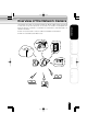
Introduction (Cont.) Accessories Introduction Confirm that all of the following accessories have been supplied with the network camera.
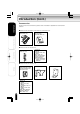
Table of Contents Introduction Introduction ● Introduction ............................................................................................................... 3 ● Table of Contents ................................................................................................... 5 ● IMPORTANT SAFETY INSTRUCTIONS ............................................................ 6 ● Precautions for Use ...............................................................................................
IMPORTANT SAFETY INSTRUCTIONS Introduction When using this camera, always follow basic safety precautions to reduce the risk of fire, electric shock, or personal injury. Installation/Setup 1. Read and understand all the instructions. 2, Keep the User's Guide for future reference. 3. Heed all warnings. 4. Follow all the instructions. 5. Wipe off any dust on the camera lens with a lens-cleaning cloth. 6.
Precautions for Use About the SD Memory Card(IK-WB11A only) Introduction ● There is a limit to the number of rewrites that is possible with the SD memory card. Replacing of the SD memory card when performing periodic maintenance of the camera is recommended. Installation/Setup ● The camera supports the following SD memory cards. Do not use memory cards with other specifications. SD memory card: 8, 16, 32, 64, 128, 256, and 512 MB SD memory cards (3.3 V) supported. Physical interface: Part 1.
About the AC adaptor Introduction Be sure to use only the supplied AC adaptor. Using a different AC adaptor may cause the camera to malfunction, heat up, or catch fire. Before using the AC adaptor, carefully read and observe the Important Safety Instructions (→page 6) and the notes below. ● ● Installation/Setup ● ● ● ● ● ● ● Do not allow the connectors on the AC adaptor to come into contact with any other metal object as this may result in short circuit.
Overview of the Network Camera Introduction The IK-WB01A/IK-WB11A network camera can deliver video images and sound in real time using the Internet or an intranet. The camera is equipped with Ethernet (RJ-45) 10BASE-T/100BASE-TX and wireless LAN IEEE 802.11b network interfaces. IK-WB11A can be used in various indoor and outdoor environments. IK-WB01A should be used indoors only.
Features of the Camera Introduction Installation/Setup Operation Others 10 ● Supports wireless LAN The camera equips the wireless LAN IEEE 802.11b system. This enables you to connect the camera and your computer without using a LAN cable. ● Built-in pan/tilt mechanism A built-in pan (left/right) and tilt (up/down) mechanism enables you to use the Internet browser to change the direction of the camera lens. The camera also comes with Scan, Presets, Auto Patrol and various other monitoring features.
Introduction ● High Sensitivity(IK-WB11A) The camera accomplishes highly sensitive night-time monitoring by using a slow-shutter speed (up to 4 seconds), Simple DAY/NIGHT function, and an auto sensitivity boost function. ● Employs ND(Neutral Density)switching mechanism(IK-WB11A) Outdoor and indoor location monitoring is made possible because of the ND switching mechanism even though the camera has a fixed-iris lens.
Setting Up the Network Camera Environment Requirements for Network Camera Monitoring System Introduction ○ Administrator's personal computer This camera cannot be used by itself. Be sure to connect the camera to a personal computer and network. This User's Guide refers to a personal computer that has been granted all privileges for configuring, operating, monitoring, and other operations as the "administrator's personal computer.
Introduction ○ Appropriate connection devices (hub, router, etc.) and LAN cable for the network system environment ・Not required if you are going to connect the personal computer and network camera directly using a wireless LAN. ・The type of LAN cable depends on the connection method used. For details, refer to "Using LAN Cable" (→ page 24).
Setting up the Network Camera Enviroment (Cont.) Introduction Names of Camera Parts(IK-WB01A) Front Lens (Focal range: 35 cm to infinity) Installation/Setup Lens cover (Transparent sphere) Side Bottom Reset button (→ page 39) Operation ・Reset the settings to the defaults by using a thin, pointed object to press the button for at least 5 seconds. (The AC adaptor must be connected) (The log information is not returned to the default state.
Introduction Names of Camera Parts (IK-WB11A) Front Sun visor (→ page 19) (Accessory) Lens (Focal range: 80 cm to infinity) Installation/Setup Lens cover (Transparent sphere) Reset button (→ page 39) Side Bottom Operation ・Reset the settings to the defaults by using a thin, pointed object to press the button for at least 5 seconds. (The AC adaptor must be connected) (The log information is not returned to the default state.
Installing the Camera (IK-WB01A) Introduction The IK-WB01A is for indoor use only. The following explains the installation procedure. Set the wall attachment to the wall ・Attach each of the four corners to the wall using four wood screws . Installation/Setup Operation Important ● Securely tighten the screws during installation to ensure not to become loosen. Connect the AC adaptor cable and the LAN cable to the camera Others ・For details, refer to "Connecting the Power Cord" (→ page 21) .
Front view Rear view Rear view Front view Rear view Installation/Setup Front Front view Introduction Set the camera to the wall attachment Operation ① Place the camera to the wall attachment at the angle shown in the picture. ② Turn the camera counter-clockwise. ・Make sure that the camera and wall attachment are properly fitting together. ③ Push down the camera perpendicularly.
Installing the Camera (IK-WB11A) Some provided parts are required for installing the camera. Introduction ● Installing the camera indoors ・Rear cover ● Installing the camera outdoors ・Rear cover ・Sun visor ■ Indoor Installation Installation/Setup Install the rear cover to the wall ・Install each of the four corners to the wall using four wood screws. Operation Important ● Securely tighten the screws during installation to ensure not to become loosen.
Introduction Connect the AC adaptor cable and the LAN cable to the camera ・For details, refer to "Connecting the Power Cord" (→ page 21) . ・If you are going to use a wireless LAN, you need to connect the AC adaptor cable only. Installation/Setup Install the camera to the rear cover ・Fix the camera to the rear cover from the sides using four M3 screws. Operation Important ● Others Take care not to trap the AC adaptor cable and LAN cable when attaching the camera to the rear cover.
Installing the Camera (IK-WB11A) (Cont.) Introduction Connect the AC adaptor cable and LAN cable to the camera ・The procedure is the same as that described in "Indoor Installation" Step 3 on page 19. Installation/Setup Attach the camera to the rear cover ・The procedure is the same as that described in "Indoor Installation" Step 4 on page 19. ・Fix the camera to the rear cover from the sides using four M3 screws.
Connecting the Power Cord Introduction Connect the power cord to the AC adaptor Installation/Setup Insert the AC adaptor plug into the camera power terminal Operation ● Others Important There is not much space around the opening of the power terminal, so make sure that the plug is properly inserted. The camera may not work properly if the plug is not inserted properly.
Connecting the Power Cord (Cont.) Introduction As shown in the figure below, use a wire clamp to fix the plug in place ・For the wire clamp, use the self-tapping screw supplied with the camera to hold. ・When the plug is fixed in place, check that it will not become disconnected by a moderate amount of pulling. Installation/Setup Turning on the Power Operation The camera has no main power switch or button. To turn the power on, insert the plug of the power cord into a power outlet.
Connecting the Camera and Personal Computer by Network ■ About the IP Address Introduction To connect to the network, the administrator needs to set the network camera IP address. There are two options to set the IP address. ・ Obtaining an IP address automatically from the DHCP server ・ Entering an IP address manually (→ page 36) ●Obtaining an IP address automatically from the DHCP server Installation/Setup The "DHCP" setting is set to "ON" by default.
Connecting the Camera and Personal Computer by Network (Cont.) Using LAN Cable Introduction The following shows two different network configurations using a LAN cable connection to operate the network camera. ・Crossover connection ・Connection via a hub ● Using a crossover cable to establish a connection (example) Installation/Setup Network camera Personal computer IP address 192.168.0.30 IP address 192.168.0.50 LAN cable (crossover) Crossover cable is not provided with the product.
Using Wireless LAN Introduction The followings show different network configurations using a wireless LAN connection to operate the network camera. ■ When using adhoc method The adhoc method is used for connecting the network camera and a personal computer. Installation/Setup Personal computer Network camera IP address 192.168.0.30 IP address 192.168.0.50 (example IP address) Adhoc method Using a wireless LAN to establish a connection requires the following conditions.
Connecting the Camera and Personal Computer by Network (Cont.) NOTE Introduction Installation/Setup ● Information may be intercepted if you use a wireless LAN connection. Improve security by using WEP key. (→ page 33) ● Communication using a wireless LAN connection is slower compared to that of a wired connection, therefore, less image frames can be delivered.
About Wireless LAN Connection Introduction There are two methods to establish the wireless LAN connection. 1. Cofiguring the wireless network environment for the camera's wireless LAN settings. 2. Cofiguring the camera's wireless LAN settings for the wireless network environment. ● Wireless LAN settings Connection mode ESS-ID Communication channel WEP : : : : Installation/Setup The default settings of the network camera are as follows: ● Network information Camera name : nwcam01 IP address : 192.168.0.
Connecting the Camera and Personal Computer by Network (Cont.) Introduction 4) Make sure of the reply from the personal computer to the network camera Start a command prompt. Type as "ping 192.168.0.30" and press "Enter" key. ● If the "Reply from..." message appears, the wireless connection is correctly established. ・ If a message other than the above appears, reconfirm that the LAN cable is not connected to another device and reconfirm the settings configured in (2) and (3).
Introduction ■ Configuring the camera's wireless LAN settings for the wireless network environment Beforehand, connect the LAN cable (straight cable) to a hub that has the power turned on or connect the LAN cable (crossover cable) to a personal computer that has the power turned on.
Connecting the Camera and Personal Computer by Network (Cont.) 6) Plug in the camera Introduction a) Confirm that the settings are the same as the wireless network environment. ● When any settings are different from the wireless network enviromment, set the same values. b) Disconnect the LAN cable from the camera. c) Unplug the camera once and plug it in again. 7) Confirm the camera connection Installation/Setup a) Ping the IP address set for the camera from a personal computer on the network.
Configuring Settings for Wireless LAN Introduction To establish a wireless connection, it is necessary for the administrator to configure the appropriate wireless LAN settings. The administrator also needs to set the IP address. For details on setting the IP address, refer to "About the IP Address" (→ page 23). Installation/Setup Perform administrator login (→ page 42) to open the Admin menu In the left side of the window, click the toggle (+) of "Network Settings" ・The sub menus appear.
Connecting the Camera and Personal Computer by Network (Cont.) Introduction Configure the communication mode ① Click ▼ for the "COM Mode" setting in the right side of the window. ② Select an item from the pull-down menu. ・If you are going to connect the network camera to the network via a wireless broadband router or access point (AP), select "infrastructure." If you are going to connect the network camera directly to a personal computer, select "adhoc.
NOTE Introduction ● This setting determines the speed of the network camera communicating with other devices on the wireless LAN. The IEEE 802.11b standard supports the communication speeds of 1.0, 2.0, 5.5, and 11 Mbps. However, it is recommended to select "auto." Configure the WEP key Installation/Setup ① Click ▼ for the "WEP Key" setting in the right side of the window. ② Select an item from the pull-down menu.
Using the Camera Search Application "Camera Finder" Introduction The camera search application "Camera Finder" is an application for searching network cameras, that can currently be viewed from the administrator's personal computer or a user's personal computer, and connecting to those cameras. You can use this application by downloading it from Toshiba website. ● Setting up "Camera Finder" Installation/Setup Access the following Toshiba Web page from the Internet URL:http://www.toshiba.
Introduction Click the camera you want to login from the list of cameras ・The chosen camera name and IP address is displayed in the Network camera log-in fields. To login as an administrator Installation/Setup Click the "Administrator" button. ・For details on Adminstrator Login procedure, refer to page 42. To login as a user Click the "User" button. To close the window without logging in Click "Exit" to close "Camera Finder" NOTE Toshiba is not responsible for any damages caused by this software.
Configuring the Network Manually ● Entering an IP address manually Introduction ・Enter an IP address manually if you are not using, or do not want to use the DHCP server. ・If you use a DHCP server, the IP address changes from time to time. Therefore, the IP address you set last time may not be valid next time, and you may not able to access to the camera. To be able to access the camera every time you use, you need to set fixed IP address (setting IP address manually) to the network camera.
Introduction Enter the camera name Installation/Setup Operation Important ● The camera name is displayed along with images in single-view or multi-view screens. If there are multiple cameras, enter a name that will make it easy to identify what the camera is monitoring. Others Set "DHCP" to "OFF" ・The default setting is "ON.
Configuring the Network Manually (Cont.) Introduction Click the save button ・The settings are registered. NOTE ● ● Installation/Setup ● Operation Others 38 Clicking the reset button restores the previous configuration. The network camera has a feature (useful for multi view) that automatically detects, and remember other cameras on the same network. If there are other cameras on the same network, it is recommended to set "Auto Identification of Other Cameras" to "ON" (→ page 51).
Log-in ID and Password Introduction Be sure to change the default login ID and password. You are able to change important information and settings of the camera through the Administrator Login. To have higher security, be sure to change your login ID and the password, and don't forget new login ID and password. Otherwise, you cannot access to the camera. In the case you forget your login ID and password, press "Reset" button (→ page 14, 15) for more than 5 seconds.
Log-in ID and Password (Cont.) Introduction In the Admin menu, click the toggle (+) of "Administrator Functions" ・The sub menus appear. Installation/Setup Operation Click "Changing the Password" ・The settings appear in the right side of the window.
Introduction Enter the login ID and password in the "Current Login ID", "Current Password", "New Login ID", "New Password", and "New Password (Confirm)" fields. Installation/Setup Operation Click the save button ・The new login ID and password are saved in the network camera.
Administrator Operation Introduction The viewing of images, listening sound and operating cameras are not restricted to the administrator. The administrator can use all the functions. However, it is necessary for the administrator to log in through the "Administrator Login" screen, because an administrator who logs in from the "User Login" screen is subject to the same restrictions as users.
Screen Part Names and Functions ● Admin Menu Screen Introduction Camera name Live button Displays images from the camera in single view. Exit button Installation/Setup Closes the settings screen. Do not use X button to close the setting screen. Always use "Exit" button to close the setting screen when you made any setting changes. Operation Main menus Sub menus Reset button Save button Saves the changes. Others Restores the previous configuration.
Screen Part Names and Functions (Cont.) Introduction ● Single View When you close the Single-View window, close the browser directly by button. pressing Camera name Sound button Switches sound on/off. Multi View button Switches the display to multi view. The button is shown only when the multi view function is set "ON". x1.0 Installation/Setup Controller button Displays the controller. Image magnification Indicates the magnification of camera images.
● Administrator Controller Introduction Camera name Close button Closes the controller. Scan button Moves the lens horizontally back and forth once. 1 shot Captures one image from camera. Auto Patrol button Back Light button Installation/Setup Moves the lens automatically at a preset angle. Performs back light compensation. Controller buttons Zoom in button Adjusts the direction of the lens by panning (left/right) and tilting (up/down). The center button moves the lens to the center position.
Screen Part Names and Functions (Cont.) ● Preset controller Introduction Preset name Installation/Setup Go button Moves the lens to the preset camera position. Set button Resisters assigned preset camera positions. Clear button Deletes assigned preset camera positions and names. Name button Changes the name of the specified preset. Operation Preset Available/Unavailable Icon Displays whether the preset is configured. Preset Selection button Specifies preset.
● Record list controller (IK-WB11A) Introduction Time and date of recording Play button Installation/Setup Plays the images recorded at a time when things are normal. You can control the recorded images by using "control buttons for playing recordings". For details, refer to the Advanced User's Guide (See cover page). Displays next 10 recordings. Displays previous 10 recordings. Operation List number Displays List numbers from #1 to #168 (Max.) in 10s.
Setting Items Introduction For more details on the settings, please refer to the Advanced User's Guide at http://www.toshiba.com/taisisd.
2)Motion Sensor IK-WB01A IK-WB11A Function ― ON/OFF Sensitivity ― HIGH, MIDDLE, LOW Size ― Detection Range ― LARGE, MEDIUM, SMALL Set from screen ranges of 8X8 squares (See Advanced User's Guide) Associate to P/T ― OFF, Preset, Auto Patrol Preset No ― 1 to 10 Resume Function ― ON/OFF Resume Time ― 10, 30, 60 seconds Introduction Item Installation/Setup Operation ※ Depending on what the camera is monitoring, the sensor may not work properly.
Setting Items (Cont.) 2)Normal Recording (Only Possible when SD Memory Card Inserted) Introduction Item IK-WB01A IK-WB11A Function ― ON/OFF Recording Cycle* ― 1, 2, 5, 10, 30, 60, 120, Timer Association ― 180 seconds ON/OFF Installation/Setup * Image can be recorded with 1 second-recording cycle when picture sizes are 160 × 120, 320 × 240, 640 × 480: 2 seconds-recorded cycle when picture sizes are 800 × 600 , 1280 × 960.
■ Network Settings Introduction 1.Network Connection Settings 1)General Settings Item IK-WB01A Camera Name Enter up to 32 single-byte Enter up to 32 single-byte characters Auto Identification of ON/OFF IK-WB11A characters ON/OFF Other Cameras ON/OFF ON/OFF IP Address Enter the static IP Enter the static IP address address Subnet Mask Enter the subnet mask Enter the subnet mask Default Gateway Enter the default gateway Enter the default gateway Installation/Setup DHCP 2)DNS Settings It
Setting Items (Cont.
7)Conditions for Sending Mail when Internal Battery Runs Out Of Power IK-WB01A IK-WB11A Send Mail When Internal ON/OFF ON/OFF Out Of Power Enter up to 256 single- Enter up to 256 single- Message Body byte characters byte characters Introduction Item Battery Runs out 8)Conditions for Sending Mail When IP Address Is Changed IK-WB01A IK-WB11A Send Mail When IP ON/OFF ON/OFF The IP address is The IP address is changed. changed.
Setting Items (Cont.
2)FTP Server Setup IK-WB01A IK-WB11A Server Name Enter the server name Enter the server name IP Address Enter the IP address Enter the IP address Login ID Enter the User ID Enter the User ID Login Password Enter the password Enter the password Login Password Reenter the password Reenter the password FTP Port Number 21 21 FTP Mode PORT/PASV PORT/PASV Connection to FTP Stay connected/ Stay connected/ Server Re-connect Re-connect Introduction Item (Confirm) Installation/Setup
Setting Items (Cont.
2.Setting the Time Item IK-WB01A Time Zone GMT-12:00∼GMT+12:00 GMT-12:00∼GMT+12:00 Introduction 1)Time Zone IK-WB11A 2)Changing the Time Manually IK-WB01A IK-WB11A Date Select a date from the Select a date from the date boxes date boxes Select a time from the Select a time from the time boxes time boxes Time Installation/Setup Item 3)Changing the Time Using an NTP Server Setting Item IK-WB01A IK-WB11A Function ON/OFF ON/OFF NTP Server Host Enter the host name Enter the host na
Setting Items (Cont.) ■ Log Management Introduction 1.Forwarding Settings Item IK-WB01A IK-WB11A Forward Log to ON/OFF ON/OFF Enter the server name Enter the server name Enter the IP address Enter the IP address Another Server Name of Destination Server IP Address of Installation/Setup Destination Server 2.Browse and Delete Settings Item IK-WB01A Log List The list of logs is displayed The list of logs is displayed * Clicking the Operation Others 58 clear button deletes the logs.
Specifications Others Designes as specifications may change without prior notice for better 59 improvement. Operation ● Installation/Setup *1: The sound may not be clear depending on the conditions of the lines. *2: The image output is for checking the image during installation. Images and sounds are not deliverd, and recording function will not work during installation. *3: The ND filter makes possible to monitor either outdoor or indoor location by controlling light intensity.
MEMO
MEMO 61
TOSHIBA AMERICA INFORMATION SYSTEMS. INC Imaging System Division 9740 Irvine Boulevard, Irvine California 92618-1697 PhoneNumber: (800)288-1354 V2.
LIMITED WARRANTY NETWORK CAMERA The Imaging Systems Division of Toshiba America information Systems, Inc. ("ISD") makes the following limited warranties with regard to this NETWORK Camera ("Product"). These limited warranties extend to the Original End-User ("You[r]"). One (1) Year Limited Warranty of Labor and Parts ISD warrants that this Product will perform in accordance with specifications for a period of one (1) year from the date of purchase by Original End-User.