
Electromagnetic Flowmeter for Partially-filled Pipes Instruction Manual


TIC-LF502A
6
■
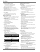
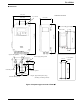
External Connections
Figure 6. LF502/LF232*F flowmeter Wiring Diagram
■
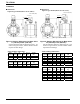
Wiring Precautions
(1) Be sure to use thick walled steel conduit (22
mm) for signal and excitation cable wiring
between the detector and converter. The
conduit screw is R (PT)1/2. Use flexible
conduits at the cable outlets of the detector as
needed.
(2) Make the grounding wire as short as possible.
Do not use a common ground shared with
other equipment where earth current may flow.
An independent earth ground is recommended.
(3) The meter may affect its accuracy when the
electric potential of measurement fluid is
unstable condition.
• Make the piping of the upstream side and
downstream side the same material.
• When the material of next pipes are conductive
like metal, use a 5.5mm
2
or larger core cable for
grounding of detector and wire it at 2 places as
follows.
• Between Grounding terminal at detector body
and Grounding ring at upstream side.
• Between Grounding terminal at detector body
and Grounding ring at downstream side.
• When the material of next pipes are
non-conductive like plastic, use a 5.5mm
2
or
larger core cable for grounding of detector and
wire 1 place as follows.
• Between Grounding terminal at detector
body and Grounding (100 ohm or less).
(4) DO1 to DO4 and DI1 to DI2 use the same
common terminal (COM). This COM can not
connect to other instruments that have their
own ground terminal (Power supply for
connecting to DI or DO, etc...). Need to wire
separately.
Power supply
Current output (4 to 20mA)
Terminal box
Digital input 1 (opt.)
(20 to 30 Vdc)
Digital input 2 (opt.)
Excitation cable
(3-wire hard-rubber sheathed cable)
Digital output
Digital output 2 (opt.)
Digital output 3 (opt.)
Digital output 4 (opt.)
Ⅳ wire
5.5mm
2
or more
Signal cable
(2-wire shielded hard-rubber sheathed cable)
Output cable
(CVV-S)
Power supply
(
CVV
)
Digital I/O cable
(CVV-S)
Thick walled steel conduit
Detector
Grounded with 100Ω o
r
less ground resistance