6F8A0870 ELECTROMAGNETIC FLOWMETER MODEL DETECTOR LF414 INSTRUCTION MANUAL NOTES Before using the equipment, please read this manual carefully and understand the contents, and then use the equipment correctly. • NEVER attempt to operate the equipment in any ways that are not described in this instruction manual. • After reading this manual, store it with care in a place where it can be referred to whenever needed.
6F8A0870 NOTICE We thank you very much for your purchase of our LF414 series electromagnetic flowmeter detector. Integral type LF414/LF600F, LF414/LF610F, LF414/LF620F Separate type detector LF414 This instruction manual describes the notes on using an electromagnetic flowmeter detector, installation, configuration and maintenance. It is intended for the personnel in charge of installation, operation and maintenance.
6F8A0870 SAFETY PRECAUTIONS Safety signs and labels affixed to the product and/or described in this manual give important information for using the product safely. They help prevent damage to property and obviate hazards for persons using the product. Make yourself familiar with signal words and symbols used for safety signs and labels. Then read the safety precautions that follow to prevent an accident involving personal injury, death or damage to property.
6F8A0870 SAFETY PRECAUTIONS Safety Precautions for Installation and Wiring WARNING Do not disconnect while circuit is live unless location is known to be nonhazardous. Live part of electric circuit or a high temperature department can cause explosion. DON’T Do not modify or disassemble the enclosure. Strength degradation and defects of enclosure can cause explosion. DON’T Do not use parts of other products. Protective performance degradation for hazardous location can cause explosion.
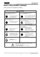
6F8A0870 SAFETY PRECAUTIONS (continued) Safety Precautions for Installation and Wiring CAUTION Install a switch and fuse to isolate the LF414/LF600F, LF414/LF610F, LF414/LF620F and LF414 from mains power. Power supply from mains power can cause electric shock or circuit break-down. Use an appropriate device to carry and install the LF414/LF600F,LF414/LF610F, LF414/LF620F and LF414. Turn off mains power before conducting wiring work.
6F8A0870 SAFETY PRECAUTIONS (continued) Safety Precautions for Maintenance and Inspection CAUTION Do not conduct wiring work with wet hands. Wet hands may result in electric shock. Do not conduct wiring work when power is applied. Wiring while power is applied can cause electric shock. DON’T DON’T Do not use a fuse other than the one specified. DON’T Using a fuse other than the one specified can cause system failure, damage or malfunction.
6F8A0870 Handling Precautions To obtain the optimum performance from the LF600F, LF610F, LF620F, LF602F, LF612F and LF622F converter for years of continuous operation, observe the following precautions. (1) Do not store or install the flowmeter in: ・Places where there is direct sunlight. ・Places where there is snow and ice Infrared switches may not function correctly. ・Places where excessive vibration or mechanical shock occurs. ・Places where high temperature or high humidity conditions obtain.
6F8A0870 Handling Precautions (continued) (5) If the inside of the converter and detector's terminal box are wetted or humidified, it may cause insulation deterioration, which can result in fault or noise occurrence. So do not conduct wiring in the open air on rainy days. Also, be careful not to wet down the converter and detector's terminal box even in the case of indoor wiring, and complete wiring work in a short period of time.
6F8A0870 Table of Contents SAFETY PRECAUTIONS ····················································································· 2 Handling Precautions ······························································································ 6 1. Product Inspection and Storage ······································································ 9 1.1 Product Inspection ······················································································· 9 1.
6F8A0870 1. Product Inspection and Storage 1.1 Product Inspection LF414 series electromagnetic flowmeter is shipped in a cardboard container filled with shock-absorbing materials. Open the package carefully and check as follows: Make sure the following items are included in the package.
6F8A0870 2. Overview The LF414/LF600F, LF414/LF610F, LF414/LF620F and LF414 electromagnetic flowmeter can be use in the following hazardous (classified) locations. ClassⅠ, Division 2, Groups A, B, C and D, ClassⅡ, Division 2, Groups E, F and G ClassⅢ This product is a converter used for electromagnetic flowmeters that measure the volumetric flow rate of conductive fluid using Faraday's law of electromagnetic induction.
6F8A0870 3. Names of Parts IMPORTANT The apparatus should not be provided with the cable connections. Please prepare yourself for the cable connections which could be used in Division2 hazardous locations. 3.1 Appearance 3.1.1 Appearance of LF414/LF600F, LF414/LF610F Integral (1) Meter size of 1/2 inch (15mm) For the detail of the converter, check the LF600F, LF610F converter's instruction manual.
6F8A0870 (2) Meter size of 1inch (25mm) For the detail of the converter, check the LF600F, LF610F converter's instruction manual. Ground terminal for converter Flow direction arrow Detector Ground terminal for detector Grounding ring Window for electrode Figure 3.1.
6F8A0870 (3) Meter size of 1 1/2 to 4 inch (40 to 100mm) For the detail of the converter, check the LF600F , LF610F converter's instruction manual. Terminal block cover Ground terminal for converter Flow direction arrow Ground terminal for detector Detector Grounding ring Figure 3.1.
6F8A0870 (4) Meter size of 6 and 8 inch (150 and 200mm) For the detail of the converter, check the LF600F, LF610F converter's instruction manual. Terminal block cover Flow direction arrow Ground terminal for converter Ground terminal for detector Grounding ring Detector Figure 3.1.4 Appearance of LF414/LF600F, LF610F Meter size 6 and 8 inch(150 and 200mm) − 14 − Lifting Lugs *Only 8 inch (200mm) provided.
6F8A0870 3.1.2 Appearance of LF414/LF620F Integral (1) Meter size of 1/2 inch (15mm) For the detail of the converter, check the LF620F converter's instruction manual. Ground terminal for converter Flow direction arrow Detector Ground terminal for detector Grounding ring Window for electrode Figure 3.1.
6F8A0870 (2) Meter size of 1inch (25mm) For the detail of the converter, check the LF620F converter's instruction manual. Ground terminal for converter Flow direction arrow Ground terminal for detector Detector Grounding ring Window for electrode Figure 3.1.
6F8A0870 (3) Meter size of 1 1/2 to 4 inch (40 to 100mm) For the detail of the converter, check the LF620F converter's instruction manual. Ground terminal for converter Flow direction arrow Ground terminal for detector Detector Grounding ring Figure 3.1.
6F8A0870 (4) Meter size of 6 and 8 inch (150 and 200mm) For the detail of the converter, check the LF620F converter's instruction manual. Ground terminal for converter Lifting Lugs *Only 8 inch (200mm) provided. Ground terminal for detector Flow direction arrow Grounding ring Detector Figure 3.1.
6F8A0870 3.1.3 Appearance of LF414 Separate (1) Meter size of 1/2 inch (15mm) Excitation cable 3/4 - 14 NPT Terminal Box Cover Signal cable 3/4 - 14 NPT Terminal Box Flow direction arrow Detector Ground terminal for detector Grounding ring Window for electrode Figure 3.1.
6F8A0870 (2) Meter size of 1inch (25mm) for Excitation cable 3/4 - 14 NPT for Signal cable 3/4 - 14 NPT Terminal Box Cover Terminal Box Flow direction arrow Detector Ground terminal for detector Grounding ring Window for electrode Figure 3.1.
6F8A0870 (3) Meter size of 1 1/2 to 4 inch (40 to 100mm) Excitation cable 3/4 - 14 NPT Signal cable 3/4 - 14 NPT Terminal Box Cover Terminal Box Flow direction arrow Detector Ground terminal for detector Grounding ring Figure 3.1.
6F8A0870 (4) Meter size of 6 and 8 inch (150 and 200mm) Excitation cable 3/4 - 14 NPT Signal cable 3/4 - 14 NPT Terminal Box Cover Terminal Box Flow direction arrow 矢印銘板 Ground terminal for detector Grounding ring Detector Figure 3.1.12 Appearance of LF414 Meter size 6 and 8 inch(150 and 200mm) − 22 − Lifting lugs *Only 8 inch (200mm) provided.
6F8A0870 3.2 Construction of the terminal blocks 3.2.1 Terminal Block Construction of LF414/LF600F, LF414/LF610F and LF414/LF620F Type Integral For details of the converter, check the LF600F, LF610F and LF620F converter's instruction manual. 3.2.2 Terminal Block Construction of LF414 Type Separate Signal cable terminal Figure 3.
6F8A0870 4. Installation Safety Precautions for Installation WARNING Do not live active circuits under environment of explosive atmospheres. Live part of electric circuit or a high temperature department can cause explosion. DON’T Do not use parts of other products. Protective performance degradation for hazardous location can cause explosion. DON’T Do not active live circuits While assembly of all components is not over.
6F8A0870 4.1 Notes on Selecting the Installation Location 1. 2. 3. Avoid places within the immediate proximity of equipment producing electrical interference (such as motors, transformers, radio transmitters, electrolytic cells, or other equipment causing electromagnetic or electrostatic interference). Avoid places where excessive pipe vibration occurs. Avoid places where fluid is pumped in a pulsating manner. Avoid places where there is direct sunlight.
6F8A0870 (2) Preventing an Empty Pipe Condition Fix the relevant pipes installed on both sides of the detector by attaching fittings, etc. to support the pipe. By supporting the pipes, not only the pipe vibration is reduced but also the damage to the pipes by the electromagnetic flowmeter's weight and the fluid mass (see Figures 4.2 and 4.3). Pipe support fittings Pipe support fittings Figure 4.2 Example of Pipe Fixing Procedure Figure 4.
6F8A0870 4.2.2 Installation Procedure To mount the LF414, place it between the upstream and downstream pipe flanges and tighten it with flange bolts and nuts. See Figure 4.4 and follow the procedure below: 1. 2. 3. 4. 5. 6. Insert two lower mounting bolts through the clearance holes in the upstream (or downstream) pipe flange. Install a packing next to the upstream (or downstream) flange face and the other packing next to the downstream (or upstream) pipe flange.
6F8A0870 Table 4.1 Bolt length and Nut tightening torque Meter size ASME B 16.5 class 150 ASME B 16.5 class 300 Through Bolts Through Bolts Tightening Tightening torque torque Dia- Length DiaLength P.C.S P.C.
6F8A0870 4.3 Piping Connections (1a) Ideal Upstream Straight Pipe Length Installation Requirements If various joints are used upstream of the detector outlet, the straight pipe length as shown in Table 4.2 is required. Table 4.2 Required straight pipe length on the upstream side L=5D L=10D (5) Other valves (not fully opened) (1) 90°bent L L (2) Tee L (3) Diffuser L (4) Fully opened sluice valve L L: Required straight pipe length—straight pipe length plus half length of the detector.
6F8A0870 (2) Pipe Orientation The detector may be installed in horizontal, vertical or sloping pipe runs as shown in Figure 4.5. However, except for horizontal installation, fluid should flow from lower to upper directions. If no air bubble, vertical down flow application are acceptable under pressured piping conditions. See Figure 4.5. Flow direction (b) Detector (a) Horizontal pipe installation (b) Vertical pipe installation (c) Sloping pipe installation (c) (a) Ground surface Figure 4.
6F8A0870 (3) Flow Direction Install the detector in accordance with the flow direction arrow on the detector. See Figure 4.7. Flow direction arrow Figure 4.7 Flow direction arrow on the detector (4) Preventing an Empty Pipe Condition Design an upright pipe run (Figure 4.8) or sufficient head pressure (Fig. 4.9) at the downstream detector outlet if there is a possibility of the detector pipe becoming emptied. Vertical pipe run Detector Figure 4.
6F8A0870 4.4 Grounding CAUTION Do not wire cables and replace parts when power is supplied. DON’T Do not work on piping and wiring with wet hands. Wet hands may result in electric shock. Wiring work and replacing parts in the power-on state may cause electric shock. DON’T (1) Grounding of the LF414/LF620F type Integral Ground as shown in Figure 4.10. Make the grounding wire as short as possible. Use grounding wire material of IV wire 5.5mm2 or more.
6F8A0870 (2) Grounding of the LF414 type Separate Ground the external grounding terminal of the detector and the FG terminal of the converter (or external grounding terminal of the converter) securely (grounding resistance 100Ω or lower). Use grounding wire material of IV wire 5.5mm2 or more. Do not share a grounding wire with other instruments where grounding current may flow. (An independent grounding is preferable.
6F8A0870 5.Wiring Safety Precautions for Wiring WARNING DO NOT DISCONNECT WHILE CIRCUIT IS LIVE UNLESS LOCATION IS KNOWN TO BE NONHAZARDOUS. Live part of electric circuit or a high temperature department can cause explosion. DON’T Do not active live circuits While assembly of all components is not over. Protective performance degradation for hazardous location can cause explosion.
6F8A0870 CAUTION Install a switch and fuse to isolate the LF414/LF600F, LF414/LF610F, LF414/LF620F and LF414 from mains power. Power supply from mains power can cause electric shock or circuit break-down. Turn off mains power before conducting wiring work. Do not work on piping and wiring with wet hands. Ground the LF600F, LF610 and LF620 independently from power equipment. (100 ohm or less ground resistance) Operating this product without grounding can cause electric shock or malfunction.
6F8A0870 Notes on wiring CAUTION (1) Select the cable runs away from electrical equipment (motors, transformers, or radio transmitters) which causes electromagnetic or electrostatic interference. (2) Deterioration of flowmeter circuit insulation occurs if the converter interior or cable ends get wet or humidified. This in turn causes malfunction of flowmeter or noise problems. Avoid a rainy day if the flowmeter is to be installed outdoors. Even indoors, prevent water from splashing over the flowmeter.
6F8A0870 5.2 External Device Connections and Grounding For the notes on connecting, wiring and installation of the combined converter, check the model number of the combined converter and read the instruction manual of the relevant converter. 5.3 Notes on Wiring 5.3.1 Notes on Instrumentation-Converter Wiring To avoid 2-point grounding, ground the shield of output cable basically at the receiving side. Use a grounding wire of IV wire 5.5mm2 or more. The size of the external grounding terminal screws is M4.
6F8A0870 5.4 Wiring 5.4.1 Terminal Treatment of Cables Follow the procedures below to treat the terminals (at the converter side) of various cables and install the cables to the terminal block. Use appropriate cables based on the description in Section 5.1 "Cables." Crimp a round type insulated crimp-type terminal to the end of the cables. (1) Power cable, current output cable, digital I/O cables The necessary cables should be ordered from the person responsible for the installation.
6F8A0870 (3) Connecting the input signal cable Separate Strip the sheath from the end of each conductor of a 2-core individually shielded cable as shown in Figure 5.4. Twist those shields and cover them with a thermal contraction tube or vinyl tube not to make contact with the case or core wires. Then attach an M3.5 crimping terminal with insulated sleeve as shown in Figure 5.3.
6F8A0870 5.4.2 Cable Connection Connect and install the terminal-treated cables to the terminal block. *Connect the cables to the terminal block securely. A loose connection may cause incorrect measurement. After connecting a cable, try to pull it to check whether it has been connected securely. Referring to combined converter's manuals of "Connections and Grounding", connect each cable to the terminal block. Tighten the screws of the terminal block tightly to ensure a secure connection.
6F8A0870 6. Operation CAUTION Do not touch the terminal board when power is supplied. Touching the terminal board when power is supplied can cause electric shock. DON’T Do not touch the main body when high temperature fluid is being measured. The fluid raises the main body temperature and can cause burns. DON’T Preparatory check Follow the procedure described below to prepare before starting the flow measurement (described with regard to the entire flowmeter).
6F8A0870 7. Maintenance and Troubleshooting Safety precaution for Maintenance and Troubleshooting WARNING Do not disconnect while circuit is live unless location is known to be nonhazardous. Live part of electric circuit or a high temperature department can cause explosion. DON’T Do not modify or disassemble the enclosure. Strength degradation and defects of enclosure can cause explosion. DON’T Do not use parts of other products.
6F8A0870 7.1 Maintenance Cleaning Adhesion might be created in the detectore over a long period of time when used on certain materials. Try to confirm whether to cause the adhesion in the detector pipe when the phenomenon is seen, and and an abnormality (ex. decreasing indication, etc.) is confirmed. Please clean with a soft brush etc. and remove any unnecessary build up inside the meter.
6F8A0870 7.2 Troubleshooting If a problem occurs while using the LF414/LF600F, LF414/LF610F, LF414/LF620F and LF414, follow the flowcharts described below. You may find a way to solve the problem. The flowcharts are based on three symptoms (1) to (3). If you cannot solve the problem, contact your nearest Toshiba representative. 7.2.1 Flow rate is not indicated START Are power supplies correct for each device? NO Use the correct power supply for each device.
6F8A0870 7.2.2 Flow rate indicated is not correct START Is the flow range correctly set? NO Set correctly. Refer to combined converter's manual. NO Perform the zero adjustment. YES Is zero point correctly set? Refer to combined converter's manual. YES Is the excitation current value as stated on the flow direction tag? NO Set correctly. Refer to combined converter's manual. YES Is the inside wall of detector YES pipe contaminated? Clean the inside of the detector pipe.
6F8A0870 7.2.3 Flow rate indication is not stable START Is power supply voltage within the specified range? NO Use a power supply within the specified range. NO Connect each cable securely to the terminal board. NO Ground the flowmeter with a copper braid or wire(5.5 mm² minimum) to a good earth ground.
6F8A0870 8. Principle of Operation The operating principle of the electromagnetic flowmeter is based on Faraday's Law of electromagnetic induction and it is designed to measure the volumetric flow rate of fluid. An insulated pipe of diameter D is placed vertically to the direction of a magnetic field with flux density B (see Figure 8.1).
6F8A0870 9. Specifications The flowmeter specifications and the type specification code used when ordering the flowmeter are described in this chapter. 9.1Specifications Meter size: 1/2, 1, 1 1/2, 2, 3, 4, 6, 8 inch (15, 25, 40, 50, 80, 100, 150, 200mm) Measurement range in terms of flow velocity: 0 – 1.0 ft/s to 0 – 32.8 ft/s ( 0 – 0.3 m/s to 0 – 10 m/s). 0 – 0.3 ft/s to 0 – 1.0 ft/s (0 – 0.1 m/s to 0 – 0.3 m/s) range is available optionally.
6F8A0870 Coating: No coating (for meter sizes 1” to 4” (25 to 100 mm)), Phthalic acid resin coating, pearl-gray colored (standard for meter size 1/2”, 6”, 8” (15,150, 200mm)) Structure: IP67 and NEMA 4X Watertight ( Standard ) Separate Cable connection port: Separate Cable length: 3/4-14NPT male screw for both signal cable and exciting cable Allowable cable length between the converter and the detector varies with the electrical conductivity of fluid. See Figure 9.
6F8A0870 Flow and calibration velocity range: It calibration by standard Range shown in the table below when Range is not specified. It calibration when there is specification by flowing quantity Range in which the customer is specified. Is this specification Range flowing quantity of Table 9.1. Please confirm becoming in the upper bound value from the flow velocity chart. Table 9.
6F8A0870 To select the meter size: See Table 9.2 to find meter sizes within the velocity of 0.3 to 32.8 ft/s (0.1 to 10m/s) for a specified full-scale (measuring range high limit) flow. Select one that has its full-scale velocity between 3.0 and 10 ft/s (1 and 3m/s). Note: Make sure the full-scale flow rate used for the final planning stage stays within 32.8 ft/s (10m/s) in terms of flow velocity. Table 9.2 Flow velocity vs. flow volume Unit: gal/min Size (inch) 1/2'' 1'' 1 1/2'' 2'' 3'' 4'' 6'' 8'' 0.
6F8A0870 9.2 Type Specification Code Table 9.
6F8A0870 Table 9.4 Type Specification Code (Exciting Cable and Signal Cable) Model Specification Code 1 2 3 4 5 6 7 8 AC C A B A 0 0 0 0 0 0 0 0 0 0 0 0 0 0 0 0 0 0 0 0 0 0 0 0 0 0 0 0 1 1 2 2 3 3 4 4 5 6 1 2 3 4 5 6 7 8 9 0 5 0 5 0 5 0 5 0 0 3 0 0 Description Dedicated preformed cable Nominal cross-sectional area of Exciting cable (Note 1) 1.25 mm² 2 mm² Nominal cross-sectional area of Signal cable (Note 2) 0.75 mm² Cable length 1m 2m 3m 4m 5m From 1 to 10 meters (3.3 to 32.
6F8A0870 10. Outline Dimensions 10.
6F8A0870 (3) Meter size of 1 1/2 to 8 inch (40 to 200mm) Meter size inch (mm) 1-1/2 (40) 2 (50) 3 (80) 4 (100) 6 (150) 8 (200) Overall lengeth L1 3.94 (100) 4.33 (110) 4.33 (110) 4.72 (120) 9.06 (230) 11.81 (300) Hight (L2) 10.39 (264) 11.02 (280) 12.05 (306) 13.31 (338) 16.02 (407) 18.03 (458) − 55 Unit : inch (mm) Diamete of flange Weight lb (kg) φD1 3.35 (85) approx 14 (6) 4.02 (102) approx 16 (7) 5.00 (127) approx 18 (8) 6.26 (159) approx 22 (10) 8.50 (216) approx 49 (22) 10.
6F8A0870 10.
6F8A0870 (3) Meter size of 1 1/2 to 8 inch (40 to 200mm) Unit : inch (mm) Meter size inch (mm) 1-1/2 (40) 2 (50) 3 (80) 4 (100) 6 (150) 8 (200) Overall lengeth L1 3.94 (100) 4.33 (110) 4.33 (110) 4.72 (120) 9.06 (230) 11.81 (300) Hight (L2) 9.80 (249) 10.43 (265) 11.46 (291) 12.72 (323) 15.43 (392) 17.44 (443) − 57 Diamete of flange φD1 3.35 (85) 4.02 (102) 5.00 (127) 6.26 (159) 8.50 (216) 10.
6F8A0870 10.
6F8A0870 (3) Meter size of 1 1/2 to 8 inch (40 to 200mm) Unit : inch (mm) Meter size inch (mm) 1-1/2 (40) 2 (50) 3 (80) 4 (100) 6 (150) 8 (200) Overall lengeth Hight L1 (L2) 3.94 (100) 7.48 (190.5) 4.33 (110) 8.15 (207.1) 4.33 (110) 9.13 (232.5) 4.72 (120) 10.39 (264.5) 9.06 (230) 13.15 (334.0) 11.81 (300) 15.16 (385.0) − 59 Diamete of flange φD1 3.35 (85) 4.02 (102) 5.00 (127) 6.26 (159) 8.50 (216) 10.
6F8A0870 Appendix 1 1-1 A system block diagram for LF414/LF600F, LF414/LF610F − 60 −
6F8A0870 1-2 A system block diagram for LF414/LF620F − 61 −
6F8A0870 2-1 A system block diagram for LF414 − 62 −
6F8A0870 Write down the address and phone number of the distributor from which you purchased this product, the product code, SER.NO. and so on. Distributor Address Name Phone number Product code ( ) − LF SER.NO.
FCF50017