INSTALLATION MANUAL MANUEL DINSTALLATION INSTALLATIONS-HANDBUCH MANUALE DI INSTALLAZIONE MANUAL DE INSTALACIÓN MANUAL DE INSTALAÇÃO INSTALLATIE HANDLEIDING ÅÃ×ÅÉÑÉÄÉÏ ÅÃÊÁÔÁÓÔÁÓÇÓ SUPER MODULAR MULTI SYSTEM AIR CONDITIONER SMMS CLIMATISEUR SMMS KLIMAGERÄT SMMS CONDIZIONATORE D'ARIA SMMS APARATO DE AIRE ACONDICIONADO SMMS AR CONDICIONADO SMMS AIRCONDITIONER SMMS ÊËÉÌÁÔÉÓÔÉÊÏ SMMS Indoor Unit Unité intérieure Raumeinheit Unità interna Unidad interior Unidade interior Binnenunit ÅóùôåñéêÞ mïíÜäá For commerc
ADOPTION OF NEW REFRIGERANT This Air Conditioner is a new type which adopts a new refrigerant HFC (R410A) instead of the conventional refrigerant R22 in order to prevent destruction of the ozone layer. UTILISATION DU NOUVEAU REFRIGERANT Ce climatiseur est d’un type inédit qui utilise le nouveau réfrigérant HFC (R410A) au lieu du réfrigérant traditionnel R22, afin d’éviter la destruction de la couche d’ozone. EINFÜHRUNG EINES NEUEN KÜHLMITTELS Dies ist ein neuartiges Klimagerät.
INHALT Zubehör und bauseits bereitzustellende Teile ............................................ 49 1 SICHERHEITSVORKEHRUNGEN ........................................................ 50 2 AUSWAHL DES AUFSTELLUNGSORTES .......................................... 51 3 INSTALLATION DER RAUMEINHEIT ................................................... 53 4 HERAUSTRENNEN EINER ÖFFNUNG UND MONTAGE DER INSTALLATIONSPLATTE .....................................................................
Accessory parts and parts to be procured locally H Accessory parts Part No. Part name (Q'ty) 1 Part No. Part name (Q'ty) 3 Installation plate × 1 2 Name Part name (Q'ty) 5 Mounting screw Ø4 × 25 l x 6 Battery × 2 4 Wireless remote controller × 1 Part No. 6 Remote controller holder × 1 Pan head wood screw Ø3.
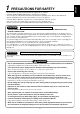
PRECAUTIONS FOR SAFETY • • • • Ensure that all Local, National and International regulations are satisfied. Read this “PRECAUTIONS FOR SAFETY” carefully before Installation. The precautions described below include the important items regarding safety. Observe them without fail. After the installation work, perform a trial operation to check for any problem. Follow the Owner’s Manual to explain how to use and maintain the unit to the customer.
1 PRECAUTIONS FOR SAFETY • Install the air conditioner securely in a location where the base can sustain the weight adequately. • Perform the specified installation work to guard against an earthquake. If the air conditioner is not installed appropriately, accidents may occur due to the falling unit. • If refrigerant gas has leaked during the installation work, ventilate the room immediately. If the leaked refrigerant gas comes in contact with fire, noxious gas may generate.
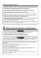
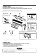
Installation space Reserve space required to install the indoor unit and for service work. Keep 100mm or more for clearance between top plate of the indoor unit and the ceiling surface. Installation diagram of Indoor and outdoor units • With the remote controller cover open, load the batteries supplied correctly, observeing their polarity.
2 SELECTION OF INSTALLATION PLACE Remote controller • A place where there are no obstacles such as a curtain that may block the signal from the indoor unit. • Do not install the remote controller in a place exposed to direct sunlight or close to a heating source, such as a stove. • Keep the remote controller at least 1m apart from the nearest TV set or stereo equipment. (This is necessary to prevent image distur-bances or noise interference.
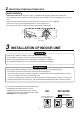
4 CUTTING A HOLE AND MOUNTING INSTALLATION PLATE Cutting a hole In case of installing the refrigerant pipes from the rear: 1. Decide the hole position for piping at 100mm from the arrow mark ( ) on the installation plate and drill a hole with Ø65mm at a slight downward slant toward outdoor side. Pipe hole 65 mm The center of the pipe hole is above the arrow. 100 mm NOTE • When drilling a wall that contains a metal lath, wire lath or metal plate, be sure to use a pipe hole brim ring sold separately.
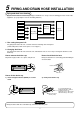
5 PIPING AND DRAIN HOSE INSTALLATION Piping and drain hose forming * Apply thermal-insulation for both refrigerant pipe and drain hose surely so that no dewing generates inside of the equipment. (Use polyethylene foam for insulating material.) Rear right Rear left Changing drain hose Bottom left Piping preparation Left Bottom right Die-cutting front panel slit Right 1. Die- cutting front panel slit For piping work at the left side, cut off the left slit for notching of the front panel.
In case of right or left piping • After scribing slits of the front panel with a knife or a marking-off pin, cut them with a pair of nippers or an equivalent tool. Slit In case of bottom right or bottom left piping • After scribing slits of the front panel with a knife or a marking- off pin, cut them with a pair of nippers or an equivalent tool. Slit Left- hand connection with piping (To the fore front of flare) Bend the connecting pipe so that it is laid within 43mm above the wall surface.
6 INDOOR UNIT FIXING 1. Pass the pipe through the hole in the wall, and hook the indoor unit on the installation plate at the upper hooks. 2. Swing the indoor unit to right and left to confirm that it is firmly hooked up on the installation plate. 3. While pressing the indoor unit onto the wall, hook it at the lower part on the installation plate. Pull the indoor unit toward you to confirm that it is firmly hooked up on the installation plate.
8 REFRIGERANT PIPING WARNING • If refrigerant gas has leaked during the installation work, ventilate the room immediately. • If the leaked refrigerant gas comes in contact with fire, noxious gas may generate. • After the installation work, confirm that refrigerant gas does not leak. • If refrigerant gas leaks into the room and flows near a fire source, such as a cooking range, noxious gas may generate. REQUIREMENT When the refrigerant pipe is long, set the support brackets to fix the pipe with 2.
8 REFRIGERANT PIPING • Projection margin in flaring : B (Unit : mm) B Airtight test/Air purge, etc. For airtight test, air purge, addition of refrigerant, and gas leak check, follow the Installation Manual attached to the outdoor unit. Rigid (Clutch type) Outer diam. of copper pipe Conventional tool used R410A tool used R410A R22 R410A R22 6.4 0 to 0.5 (Same as left) 1.0 to 1.5 0.5 to 1.0 9.5 0 to 0.5 (Same as left) 1.0 to 1.5 0.5 to 1.0 12.7 0 to 0.5 (Same as left) 1.0 to 1.5 0.
9 ELECTRIC WORK WARNING 1. Using the specified wires, ensure to connect the wires, and fix wires securely so that the external strength of the wires do not transmit to the connecting part of the terminals. Incomplete connection or fixation may cause a fire, etc. 2. Be sure to connect earth wire. (Grounding work) Do not connect the earth wire to gas pipe, city water pipe, lightning rod, or the earth wire of telephone. Incomplete grounding causes an electric shock. 3.
9 ELECTRIC WORK Indoor unit power supply (*1) • For the power supply of the indoor unit, prepare the exclusive power supply separated from that of the outdoor unit. • Arrange the power supply, earth leakage breaker, and main switch of the indoor unit connected to the same outdoor unit so that they are commonly used. • Power supply cord specification : Cable 3-core 2.5mm², in conformity with Design 60245 IEC 57.
• Tighten the screws of the terminal block, and fix the cables with cord clamp attached to the electric parts box. (Do not apply tension to the connecting section of the terminal block.
9 ELECTRIC WORK Remote controller wiring • Strip off approx. 14mm cover of the wire to be connected. • Twist wire of the remote controller to be connected with wire of the remote controller unit (or sensor), and press-fit them with a wire joint. (Wire joints (White: 2 pieces) are included in the accessory of the main remote controller (sold separately) or wireless remote controller kit (sold separately).
10 APPLICABLE CONTROLS NOTIFICATION When using the equipment at the first time, it will take a lot of time that the remote controller accepts an operation after power was on. However, it is not a trouble. • Automatic address • While automatic addressing, the operation cannot be performed on the remote controller. • For automatic addressing, Max. 10 minutes (generally, approx. 5 minutes) are required. • When power will be turned on after finish of automatic addressing; • It will require Max.
10 APPLICABLE CONTROLS Change of lighting time of filter sign Adjustment of air direction According to the installation condition, the lighting time of the filter sign (Notification of filter cleaning) can be changed. Follow to the basic operation procedure (1 → 2 → 3 → 4 → 5 → 6 ). • For the item code in Procedure 3 , specify [01]. • For the [Set data] in Procedure 4 , select the setup data of filter sign lighting time from the following table.
11 TEST RUN Before test operation WARNING • Before turning on the power supply, carry out the following items. To protect the compressor at 1) Using 500V-megger, check there is 1MΩ or more between the starting time, keep power-ON terminal block of the power supply and the earth. If 1MΩ or less condition before 12 hours or more. is detected, do not run the unit. 2) Check that all the valves of the outdoor unit are fully opened.
11 TEST RUN In case of wireless remote controller (Forced test operation is performed in a different way.) REQUIREMENT 1. For the operation procedure, be sure to follow the Owner’s Manual. 2. Finish the forced cooling operation in a short time because it applies excessive strength to the air conditioner. 3. A test operation of forced heating is unavailable. Perform a test operation by heating operation using the switches of the remote controller.
12 TROUBLESHOOTING Confirmation and check When a trouble occurred in the air conditioner, the check code and the indoor unit No. appear on the display part of the remote controller. The check code is only displayed during the operation. If the display disappears, operate the air conditioner according to the following “Confirmation of error history” for confirmation. CODE No. UNIT No. R.C. Check code No. Indoor unit No.
12 TROUBLESHOOTING Check method On the remote controller (Main remote controller, Central control remote controller) and the interface P.C. board of the outdoor unit (I/F), a check display LCD (Remote controller) or 7-segment display (on the outdoor interface P.C. board) to display the operation is provided. Therefore the operation status can be known. Using this self-diagnosis function, a trouble or position with error of the air conditioner can be found as shown in the table below.
Main remote controller display Check code Wireless remote controller Outdoor 7-segment display Sensor block display of receiving unit Auxiliary code Operation Timer Ready l l l l Compressor break down F10 — — F12 F12 — F13 F13 01: Comp. 1 side 02: Comp. 2 side F15 F15 — F16 F16 — F23 F23 — F24 F24 — F29 — — F31 F31 — H01 H01 01: Comp. 1 side 02: Comp. 2 side l H02 H02 01: Comp. 1 side 02: Comp.
12 TROUBLESHOOTING Check code Main remote controller display Wireless remote controller Sensor block display of receiving unit Outdoor 7-segment display Check code name Judging device Auxiliary code Operation Timer Ready Flash P01 — — l ¤ ALT Indoor fan motor error P03 P03 — ALT Discharge temp. TD1 error P04 P04 01: Comp. 1 side 02: Comp.
New check code 1. Difference between the new check code and the current system The displaying method of the check code changes in this model and after. Check code in current system New check code Used characters Hexadecimal notation, 2 digits Alphabet + Decimal notation, 2 digits Characteristics of code classification Few classification of communication/incorrect setup system Many classification of communication/incorrect setup system Block display Indoor P.C. board, Outdoor P.C.
WARNINGS ON REFRIGERANT LEAKAGE Important Check of Concentration Limit The room in which the air conditioner is to be installed requires a design that in the event of refrigerant gas leaking out, its concentration will not exceed a set limit. The refrigerant R410A which is used in the air conditioner is safe, without the toxicity or combustibility of ammonia, and is not restricted by laws to be imposed which protect the ozone layer.
CONFIRMATION OF INDOOR UNIT SETUP Prior to delivery to the customers, check the address and setup of the indoor unit, which has been installed in this time and fill the check sheet (Table below). Deta of four units can be entered in this check sheet. Copy this sheet according to the No. of the indoor units. If the installed system is a group control system, use this sheet by entering each line system into each installation manual attached to the other indoor units.