FILE NO. A06-002 SERVICE MANUAL MMU-AP0071MH MMU-AP0091MH MMU-AP0121MH MMU-AP0151MH MMU-AP0181MH • This Service Manual describes contents of the Compact 4-Way Air Discharge Cassette indoor unit. For the outdoor unit, refer to the Manual with FILE No. A03-009, A05-004, A05-015. PRINTED IN JAPAN, Apr.
CONTENTS SAFETY CAUTION ............................................................................................ 3 1. CONSTRUCTION VIEWS (EXTERNAL VIEWS) ........................................ 8 2. WIRING DIAGRAM ..................................................................................... 9 3. PARTS RATING ........................................................................................ 10 4. REFRIGERATING CYCLE DIAGRAM ...................................................... 34 5.
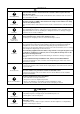
SAFETY CAUTION The important contents concerned to the safety are described on the product itself and on this Service Manual. Please read this Service Manual after understanding the described items thoroughly in the following contents, and keep them. WARNING Check earth wires. Before troubleshooting or repair work, check the earth wire is connected to the earth terminals of the main unit, otherwise an electric shock is caused when a leak occurs.
WARNING Assembly/Cabling Insulator check Ventilation After repair work, surely assemble the disassembled parts, and connect and lead the removed cables as before. Perform the work so that the cabinet or panel does not catch the inner cables. If incorrect assembly or incorrect cable connection was done, a disaster such as a leak or fire is caused at user’s side.
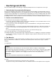
• New Refrigerant (R410A) This air conditioner adopts a new HFC type refrigerant (R410A) which does not deplete the ozone layer. 1. Safety Caution Concerned to New Refrigerant The pressure of R410A is high 1.6 times of that of the former refrigerant (R22). Accompanied with change of refrigerant, the refrigerating oil has been also changed.
4. Tools (1) Required Tools for R410A Mixing of different types of oil may cause a trouble such as generation of sludge, clogging of capillary, etc. Accordingly, the tools to be used are classified into the following three types.
5. Recharge of Refrigerant When recharge of the refrigerant is required, charge the new refrigerant with the specified amount in the procedure as described below. Recover the refrigerant and check there is no refrigerant in the equipment. When the pressure has lowered until indication of the compound gauge pointed -0.1MPa (–76cmHg), open fully the handle Low and turn off the power of vacuum pump.
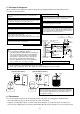
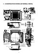
1. CONSTRUCTION VIEWS (EXTERNAL VIEWS) 200 595 to 660 Ceiling open dimension 1000 or more 15 or more 1000 or more Space required for installation and servicing Drain-up standing-up size Stand-up 850 or less Indoor unit Bottom face of ceiling Note) As ABS is used for the drain discharge port of the main unit, the vinyl chloride paste cannot be used. Use the flexible hose (Band fix) included in the package. 4 207 175 149 200 Check port ( 450) 2.
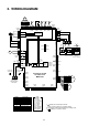
2. WIRING DIAGRAM PMV 6 4 3 1 2 5 6 4 3 1 2 5 TC1 1 2 3 4 5 6 1 2 3 4 5 6 1 3 1 2 3 1 3 1 2 3 CN82 (BLU) CN100 (BRW) CN34 (RED) CN333 (WHI) 5 5 TA FS 1 2 1 2 TCJ 1 2 1 2 TC2 1 2 1 2 CN309 (YEL) 3 1 CN41 (BLU) BLK 3 3 2 BLK 1 1 CN104 CN102 CN101 (YEL) (RED) (BLK) Motor drive circuit 3 3 CN40 (BLU) 1 1 5 2 2 5 1 1 CN334 (WHI) 5 5 4 4 3 2 1 1 U1 U2 CN68 (BLU) 1 1 CN71 1 (CHK) 2 CN72 1 (DISP) 2 WHI CN80 (GRN) RY303 3 3 3 Fuse T3.15A 250V ~ Fuse T6.
3. PARTS RATING 3-1.
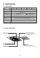
3-3. Parts Name of Remote Controller Display section CODE No. SET DATA SETTING TEST In the display example, all indicators are displayed for the explanation. In reality only, the selected contents are indicated. • When turning on the leak breaker at the first time, [SET DATA] flashes on the display part of the remote controller. While this display is flashing, the model is being automatically confirmed.
Operation section Push each button to select a desired operation. This remote controller can operate the maximum 8 indoor units. • The details of the operation needs to be set up once, afterward, the air conditioner can be used by pushing ON / OFF button only. 1 7 TEMP. 10 2 5 FILTER RESET TEST ON / OFF TIMER SET FAN MODE TIME SWING/FIX VENT SET CL UNIT 8 9 4 6 3 1 2 3 4 5 6 7 8 Air volume select button Selects the desired air volume mode.
3-4. Correct Usage When you use the air conditioner for the first time or when you change the SET DATA value, follow the procedure below. From the next time, the operation displayed on the remote controller will start by pushing the ON / OFF button only. Preparation Turn on the main power switch and/or the leakage breaker. • When the power supply is turned on, a partition line is displayed on the display part of the remote controller.
3-5. Automatic Operation (Super Heat Recovery Type Only) When you set the air conditioner in mode or switch over from AUTO operation because of some settings change, it will automatically select either cooling, heating, or fan only operation depending on the indoor temperature. TEMP. ON / OFF 3 TIMER SET FAN MODE TIME SWING/FIX VENT FILTER RESET TEST SET CL 1 2 UNIT Start 1 2 3 ON / OFF button Push this button to start the air conditioner. Mode select button (MODE) Select Auto.
3-6. TIMER Operation A type of timer operation can be selected from the following three types. OFF timer : The operation stops when the time of timer has reached the set time. Repeat OFF timer : Every time, the operation stops after the set time has passed. ON timer : The operation starts when the time of timer has reached the set time. Timer operation TEMP. 1 FILTER RESET TEST ON / OFF TIMER SET FAN MODE TIME SWING/FIX VENT SET CL 2 UNIT 34 1 2 3 Push TIMER SET button.
3-7. Adjustment of Wind Direction • While the air conditioner stops, the horizontal flap (Up/Down air direction adjustment plate) automatically directs upward. • While the air conditioner is in ready status for heating, the horizontal flap (Up/Down air direction adjustment plate) directs upward. The swinging operation starts after heating ready status has been cleared, but “SWING ” is displayed on the remote controller even if the status is ready to heating.
3-8. Information Confirmation before operation Protective device (High pressure switch) • Turn on the power switch 12 hours before starting the operation. • Make sure whether earth wire is connected. • Make sure the air filter is connected to the indoor unit. This device stops automatically an operation when excessive force is applied on the air conditioner. If the protective device works, the operation stops and the operation lamp flashes.
3-9. Air Conditioner Operations and Performance 3 minutes protection function 3-minutes protection function prevents the air conditioner from starting for initial 3 minutes after the main power switch/circuit breaker is turned on for re-starting the air conditioner. Power failure Power failure during operation will stop the unit completely. • To restart the operation, push the START/STOP button on the remote controller.
3-10. When the Following Symptoms are Found Check the points described below before asking repair servicing. Check again. Symptom Outdoor unit • White misty cold air or water is out. • Sometimes, noise “Pushu !” is heard. • Fan of the outdoor unit stops automatically and performs defrost operation. • Solenoid valve works when defrost operation starts or finishes. Indoor unit • “Swish” sound is heard sometimes.
Accessory parts and Parts to be procured locally H Accessory parts Q’ty Shape Installation Manual 1 This manual Heat insulating pipe 2 Installation pattern 1 Part name Usage (Ensure hand over to customer) For heat insulation of the pipe connecting section —— For checking of ceiling opening and the main unit position For positioning of the ceiling position (To be used with the installation pattern) Installation gauge 2 Pattern fixing screw 4 Heat insulator 1 For heat insulation of drain co
1 PRECAUTIONS FOR SAFETY • Install the air conditioner securely in a location where the base can sustain the weight of the unit adequately. • Perform the specified installation work to guard against an earthquake. Installation space Ensure there is sufficient space to install the unit and to perform maintenance work as and when required. Keep 15mm or more for clearance between top plate of the indoor unit and the ceiling surface.
SELECTION OF INSTALLATION PLACE Dimensional view In case of wireless type 200 200 200 Stand-up 850 or less Ceiling Note) As ABS is used for the drain discharge port of the main unit, the vinyl chloride paste cannot be used. Use the flexible hose (Band fix) included in the package. 120 • Wired remote controller (RBC-AMT31E) 16 368.5 235 Ø162 320.
3 INSTALLATION OF INDOOR UNIT Ceiling opening and installation of hanging bolts Installation of indoor unit • Evaluate and determine the piping and wiring requirements inside the ceiling prior to the hanging of the unit. • After installation place of the indoor unit has been determined, create opening in ceiling and install the hanging bolts. • For the ceiling opening size and pitch for hanging bolts refer to the dimensional drawing and the supplied installation pattern.
DRAIN PIPING WORK Pipe material/Insulator and size • Install the drain piping so that the water drains effectively. Connection of drain pipe The following materials for piping work and insulation are to be procured locally. Hard vinyl chloride pipe socket for VP25 • Apply heat insulation to prevent dew condensation from forming. Pipe material • Incorrectly installed pipe work may result in a water leak. Insulator Hard vinyl chloride pipe VP25 (Outer diameter Ø32 mm) REQUIREMENT 1.
4 5 DRAIN PIPING WORK REFRIGERANT PIPING WARNING Thermal insulating process • After checking of the draining, using the supplied thermal insulation fit to the flexible hose leaving no clearance at the connecting port of the indoor unit. • Fit locally procured thermal insulation to the drain pipe leaving no clearance between the supplied insulation. Flexible hose Hose band • If refrigerant gas leaks during the installation work, ventilate the room immediately.
5 6 REFRIGERANT PIPING • Projection margin in flaring : B (Unit : mm) B Outer diam. of copper pipe Conventional tool used R410A tool used R410A R22 R410A R22 6.4 0 to 0.5 (Same as left) 1.0 to 1.5 0.5 to 1.0 9.5 0 to 0.5 (Same as left) 1.0 to 1.5 0.5 to 1.0 12.7 0 to 0.5 (Same as left) 1.0 to 1.5 0.5 to 1.0 15.9 0 to 0.5 (Same as left) 1.0 to 1.5 0.5 to 1.0 WARNING Airtight test/Air purge, etc.
ELECTRIC WORK Power supply specifications Cable connection Power supply wiring and communication wiring are to be procured locally. For the power supply specification, follow the table below. Ensure power supply is adequate. An insufficient power supply could result in unit failure. For specification of the power capacity of the outdoor unit and the power supply wires, refer to the Installation Manual supplied with the outdoor unit.
6 7 ELECTRIC WORK APPLICABLE CONTROLS NOTIFICATION Remote controller wiring • Strip approximately 14 mm of insulation off of the connecting wires. • As the remote controller wire has no polarity, there is no problem if connections to indoor unit terminal blocks A and B are reversed.
7 APPLICABLE CONTROLS In case of installation to high ceiling Change of lighting time of filter sign When the unit is to be installed at a height that exceeds the standard value, adjustment to the air volume is necessary. • For the “Setup data” in Procedure 2 , select from the “Installable ceiling height list”.
8 TEST RUN Before test operation In case of wireless remote controller WARNING • Before turning on the power supply, carry out the following procedures. 1) Using 500V-megger, check there is 1MΩ or more between the terminal block of the power supply and the earth. If 1MΩ or less is detected, do not run the unit. 2) Check that all the valves of the outdoor unit are fully opened. To protect the compressor at startup. Ensure the power supply is left on for 12 or more hours before operation.
9 TROUBLESHOOTING Confirmation and check Check method When a fault occurs in the air conditioner, the check code and the indoor unit No. will appear on the display part of the remote controller. The check code will only be displayed while the unit is in operation. If the display disappears, operate the air conditioner according to the following “Confirmation of error history” for confirmation. On the remote controller (Main remote controller, Central control remote controller) and the interface P.C.
9 TROUBLESHOOTING Wireless remote controller ¤ ¤ ¤ ¤ ¤ ¤ ¤ ¤ ¤ ¤ ¤ ¤ ¤ ¤ ¤ ¤ ¤ ¤ ¤ ¤ ¤ ¤ ¤ ¤ ¤ ¤ l l l ¤ ¤ ¤ ¤ ¤ ¤ ¤ ¤ ¤ ¤ l ¡ ¡ ¡ ¤ ¤ ¤ ¤ ¤ ¤ ¤ ¤ ¤ ¤ 01: IPDU1 error 02: IPDU2 error 03: IPDU3 error 04: Fan IPDU error 05: IPDU1 + Fan IPDU error 06: IPDU2 + Fan IPDU error 07: All IPDU error ¤ ¡ ¤ Detected indoor address ¤ — — F02 — — F03 — — F04 F04 — F05 F05 — F06 F06 — F07 F07 — F08 F08 — F10 — — F12 F12 — F13 F13 F15 F15 — F16 F16 — 01: Comp.
9 10 TROUBLESHOOTING MAINTENANCE Prior to maintenance, ensure the power supply is turned off. New check code CAUTION 1. Difference between the new check code and the current system The displaying method of the check code will change from this model onwards. New check code Do not handle the buttons with wet hands as this will cause the risk of electric shock.
4. REFRIGERATING CYCLE DIAGRAM Liquid side Gas side Strainer Capillary tube Air heat exchanger at indoor side Pulse Motor Valve (PMV) Strainer Sensor (TCJ) Sensor (TC2) Fan Sensor (TC1) Sensor (TA) Temp.
5. CONTROL OUTLINE 5-1. Control Specifications No. Item Outline of specifications Remarks 1 Power supply is reset. 1. Distinction of outdoor unit When the power supply is reset, the outdoor units are distinguished, and control is exchanged according to the distinctive results. 2. Check code clear When the power supply is reset, the check code is also reset once.
No. 6 Outline of specifications Item Prevention of cold air discharge 1. In all heating operation, the upper limit of the fan tap is set by one with higher temperature of TC2 sensor and TCJ sensor. • When B zone has continued for 6 minutes, the operation shifts to C zone. • In defrost time, the control point is set to +6°C. (˚C) 32 E C 28 26 20 B 16 Freeze prevention control (Low temp. release) • In D and E zones, priority is given to remote controller air speed setup. • In A “ ” is displayed.
No. Item Outline of specifications Remarks 8 Recovery control for cooling refrigerant and oil 1. The indoor unit which stops operation, thermostat is OFF, or operates in FAN mode opens PMV of the indoor unit by the specified opening degree when cooling refrigerant or oil recovery signal is received from the outdoor unit. 2. Drain pump of Compact 4-way Air Discharge Cassette type operates during recovery control mode. • Recovery operation is usually executed every 2 hours.
No. Item 15 “ ” and “ ” display (Operation and heating stand-by) Remarks Outline of specifications .......... Display on remote controller 1. • “P05” is one of displays of power wire missing. • “P05” of power cable is detected. • “COOL/DRY” operation cannot be performed because the other indoor unit is under “HEAT” operation. • “HEAT” operation cannot be performed because COOL priority is set (Outdoor I/F P.C.
6. APPLIED CONTROL 6-1. Setup of Selecting Function in Indoor Unit (Be sure to Execute Setup by a Wired Remote Controller) Execute the setup operation while the unit stops. TEMP. 3 5 6 FILTER RESET TEST ON / OFF TIMER SET FAN MODE TIME SWING/FIX VENT SET CL 4 UNIT 1 1 Push SET , 2 CL , and TEST buttons simultaneously for 4 seconds or more. The firstly displayed unit No. indicates the header indoor unit address in the group control.
Table: Function selecting item numbers (DN) (Items necessary to perform the applied control at the local site are described.) Item DN Description 01 Filter display delay timer 0000 : None 0002 : 2500H 0004 : 10000H 02 Dirty state of filter 0000 : Standard 0001 : High degree of dirt (Half of standard time) 0000 : Standard 03 Central control address 0001 : No.1 unit 0099 : Unfixed 0064 : No.
TYPE Indoor unit capacity Item code [10] Item code [11] Setup data Type Abbreviated Model name 0014 Compact 4-way Air Discharge Cassette MMU-AP XXX MH Setup data Model 0001 007 0003 009 0005 012 0007 015 0009 018 6-2. Applied Control in Indoor Unit n Remote location ON/OFF control box (TCB-IFCB-4E) [Wiring and setup] • Use the exclusive connector for connection with the indoor control P.C. board.
n Ventilating fan control from remote controller [Function] • The start/stop operation can be operated from the wired remote controller when air to air heat exchanger or ventilating fan is installed in the system. • The fan can be operated even if the indoor unit is not operating. • Use a fan which can receive the no-voltage A contact as an outside input signal. • In a group control, the units are collectively operated and they can not be individually operated.
n Leaving-ON prevention control [Function] • This function controls the indoor units individually. It is connected with cable to the control P.C. board of the indoor unit. • In a group control, it is connected with cable to the indoor unit (Control P.C. board), and the item code - is set to the connected indoor unit. • It is used when the start operation from outside if unnecessary but the stop operation is necessary.
7. TROUBLESHOOTING 7-1. Troubleshooting Summary 1. Before troubleshooting 1) Applied models Q S-MMS Multi type models Indoor unit: MMX-APXXX, Outdoor unit: MMY-MAPXXXHT8, MMY-MAPXXXT7 R Super Heat Recovery Multi type models Indoor unit: MMX-APXXX, Outdoor unit: MMY-MAPXXXFT8 S Mini-S-MMS Multi type models Indoor unit: MMX-APXXX, Outdoor unit: MCY-MAPXXXHT, MCY-MAPXXXHT2D 2) Required tools / measuring devices • Screwdrivers (Philips, Minus), spanner, radio pinchers, nipper, push pin for reset switch, etc.
7-2. Check Method On the remote controller (Main remote controller, Central control remote controller) and the interface P.C. board of the outdoor unit, a check display LCD (Remote controller) or 7-segment display (on the outdoor interface P.C. board) to display the operation is provided. Therefore the operation status can be known. Using this self-diagnosis function, a trouble or position with trouble of the air conditioner can be found as shown in the table below.
Check code Main remote controller display Wireless remote controller Sensor block display of receiving unit Outdoor 7-segment display Auxiliary code F01 — — F02 — — F03 — — F04 F04 — F05 F05 — F06 F06 — F07 F07 — F08 F08 — F10 — — F12 F12 — 01: Comp. 1 side 02: Comp.
Check code Main remote controller display Wireless remote controller P01 — P03 P03 Auxiliary code Operation — l P04 P04 P05 P05 01: Phase-missing detection 02: Phase error P07 P07 01: Comp. 1 side 02: Comp.
The check code 1. The TCC LINK check code The displaying method of the check code. TCC Link Used characters Alphabet + Decimal notation, 2 digits |→ Characteristics of code classification Many classification of communication/ incorrect setup system Block display Communication/Incorrect setup (4 ways), Indoor protection, Outdoor protection, Sensor, Compressor protection, etc.
7-3. Troubleshooting by Check Display on Remote Controller In case of wired remote controller (RBC-AMT31E) 1. Confirmation and check CODE No. When a trouble occurred on the air conditioner, the check code and the indoor unit No. are displayed on the display section of the remote controller. The check code is displayed while the air conditioner operates. If the display disappeared, operate the air conditioner and check the error based upon the following “Confirmation of error history”. UNIT No. R.C.
In case of central remote controller (TCB-SC642TLE) ZONE ALL ZONE GROUP CODE No. 1234 SET DATA SETTING R.C. UNIT No. TEST No. GROUP SELECT ZONE CL SET 1. Confirmation and check When a trouble occurred on the air conditioner, the check code and the indoor unit No. are displayed on the display section of the remote controller. The check code is displayed while the air conditioner operates.
7-4. Check Code and Check Position Displayed on the Remote Controller and Outdoor Unit (7-Segment Display of Interface) Check code Outdoor 7-segment display Main remote controller Check code Auxiliary code Detected position Check code name Status Error detection condition Check item (position) 51 E01 — — Remote controller Communication error between Corresponding Communication interrupted between indoor and remote controller unit only stops. indoor P.C.
Check code Main Outdoor 7-segment display remote Auxiliary code controller Check code Detected position Check code name Status Check item (position) Error detection condition 52 E12 E12 01: Indoor/outdoor communication 02: Between outdoors communication I/F Automatic address start error All stop • When indoor automatic address started, other refrigerant circuit system was setting automatic address. • When outdoor automatic address started, indoor automatic address was executed.
Check code Detected position Check code name Status I/F IPDU communication error All stop 53 Main remote controller Check code E31 E31 F01 — — Indoor unit Indoor TCJ sensor error Corresponding • Resistance value of sensor is infinite or zero. • Check connection/cabling of TCJ sensor connector. unit only stops. (Open/Short) • Check characteristics of TCJ sensor resistance value. • Check indoor P.C. board error.
Check code Main remote controller Outdoor 7-segment display Check code Auxiliary code F13 F13 01: Compressor 1 side 02: Compressor 2 side F15 F15 — F16 F16 F23 Detected position Status Error detection condition Check item (position) 54 TH sensor error All stop • Resistance value of sensor is infinite or zero (Open/Short). • IGBT built-in temp sensor error → Exchange IPDU P.C. board.
Check code Outdoor 7-segment display Main remote controller Check code Auxiliary code H03 H03 01: Compressor 1 side Detected position Check code name Status IPDU Current detection circuit system error All stop While header compressor stopped, current flowed • Check cabling of current detection circuit system. more than the specified current and was detected. • Check outdoor P.C. board (IPDU) error.
Check code Main remote controller Outdoor 7-segment display Check code Auxiliary code H07 H07 — Detected position Check code name Status Error detection condition I/F Protection for oil level drop detection All stop The operating compressor detected oil shortage continuously for 2 hours. Check item (position) • Check full opening of service valve of balance pipe. • Check connection and installation of TK1, TK2, TK3, and TK4 sensors.
Check code Main Outdoor 7-segment display remote Auxiliary code controller Check code H16 H16 01: TK1 oil circuit system error Detected position Check code name Status Error detection condition I/F Oil level detective circuit system error All stop Temperature change of TK1 could not be detected though compressor 1 started the operation.
Check code Main remote controller Check code L06 L06 L07 — L08 L08 Detected position Check code name Status I/F Duplicated indoor units with priority (Displayed on the unit other than indoor unit with priority) All stop — Indoor Group line in individual indoor unit. Corresponding At least one indoor unit connected unit only stops. to a group existed in the individual indoor units. • Check indoor address. — Indoor Indoor group / address unset Corresponding Address was not yet set up.
Check code Outdoor 7-segment display Detected position Status Error detection condition Main remote controller Check code Auxiliary code P01 — — Indoor P03 P03 — I/F Discharge temp TD1 error All stop Discharge temp (TD1) exceeded 115°C. • • • • • • • • • • • P04 P04 01: Compressor 1 side 02: Compressor 2 side I/F Actuation of high-pressure SW All stop High-pressure SW actuated.
Check code Main Outdoor 7-segment display remote Auxiliary code controller Check code Detected position Check code name Status Check item (position) Error detection condition P07 P07 01: Compressor 1 side 02: Compressor 2 side IPDU I/F Heat sink overheat error All stop IGBT built-in temp sensor (TH) was overheated. • • • • • Check power voltage. Check outdoor fan system error. Check clogging of heat sink cooling duct. Check fixation between IGBT and heat sink. (Check screwing and contact.
Check code Main Outdoor 7-segment display remote Auxiliary code controller Check code Detected position Check code name Status Check item (position) Error detection condition P17 — I/F Discharge temp TD2 error All stop Discharge temperature (TD2) exceeded 115°C. P19 P19 Detected outdoor unit No. I/F 4-way valve operation error All stop When abnormal refrigerating cycle • Error of 4-way valve error. data was detected in heating • Check coil error and connector connection of 4-way valve.
Check code Outdoor 7-segment display Main remote controller Check code Auxiliary code P22 P22 0: IGBT shortage Detected position Check code name FAN-IPDU Outdoor fan IPDU error Status All stop Error detection condition (Auxiliary code: 0) Check item (position) • Check fan motor. (Interphase short-circuit) 1: Position detection circuit error • Short-circuit current was detected at start time. • Check fan IPDU error.
Error detected by TCC-LINK central control device Check code Outdoor 7-segment display Display on central control device Check code C05 — Detected position Check code name TCC-LINK TCC-LINK central control device transmission error Status Error detection condition Check item (position) Auxiliary code Operation Signal is not transmit from continued. central control device. • Check central control device error. • Check communication line error of central control device.
Cautions when servicing for compressor 1. Removing wires of both compressors check output of the inverter as described below. How to check inverter output 1. Turn off the power supply. 2. Remove the compressor lead cables from the compressors. (Be sure to remove lead cables of both compressors.) 3. Turn on the power supply and start cooling or heating operation.
7-5. Diagnosis Procedure for Each Check Code Check code Check code name [E01] Cause of operation Communication error between 1. Remote controller inter-unit cable error indoor and remote controller 2. Indoor power error (Detected at remote controller side) 3. Indoor P.C. board error 4. Remote controller address setup error 5. Remote controller P.C. board error Is the inter-unit cable of remote controllers (A/B) normal? NO Correct inter-unit cable of remote controller.
Check code Check code name [E06] Cause of operation Decreased number of indoor units 1. Communication lines (U1, U2) connection Check code Check code name Cause of operation [E07] Indoor/Outdoor communication circuit error (Detected at outdoor side) 1. Indoor/outdoor communication end terminal resistance setup error 2. Indoor/outdoor communication connection error error between indoor and outdoor 2. Connector connection error of communication for indoor P.C. board 3.
Check code Check code name [E08] Duplicated indoor addresses Cause of operation Indoor addresses are duplicated. Check code Check code name [E12] Automatic address start error Auxiliary code : Duplicated indoor address Using a main remote controller (RBC-AMT21E), check the setup item codes (DN code) 12, 13, and 14. When there is no address duplication, check to the following flowchart. NO Is cable connection to communication line normal? Correct wire connection. Cause of operation 1.
Check code Check code name [E16] Connected indoor units capacity over Auxiliary code : 00 : Capacity over Cause of operation 1. There are 48 or more connected indoor units. 2. Capacity over of total connected indoor units. 3. Incorrect setup of indoor/outdoor capacity Check code Check code name Cause of operation [E18] Communication error between indoor header and follower Regular communication between indoor header and follower is unavailable.
Check code Check code name [E20] Unit connected to other line during automatic address Cause of operation When starting automatic indoor address, a device in other line is connected. Auxiliary code : 01: Connection of outdoor in other line 02: Connection of indoor unit in other line Check code Check code name Cause of operation [E25] Duplicated address setup of terminal outdoor units Addresses are duplicated by manual setting of outdoor address Never set up the outdoor address manually.
Check code Check code name [E31] IPDU communication error Cause of operation 1. Connection error of communication line between IPDU and I/F P.C. board 2. I/F P.C. board error 3. IPDU P.C. board error 4. External noise Check code Check code name [F01] Indoor TCJ sensor error Is TCJ sensor connector (CN102: Red) on indoor P.C. board normally connected? NO Cause of operation TCJ sensor Open/Short Correct connection of connector.
Check code Check code name [F04] TD1 sensor error Cause of operation TD1 sensor Open/Short This error code means detection of Open/Short of TD1 sensor. Check disconnection of circuit for connection of connector (TD1 sensor: CN502, White) and characteristics of sensor resistance value. (Refer to Outdoor unit temperature sensor characteristics.) If sensor is normal, replace outdoor I/F P.C. board.
Check code name Check code name [F15] Outdoor temp sensor miscabling (TE1, TL) Cause of operation 1. Misinstallation and misconnection of TE1 sensor and TL sensor 2. Resistance characteristics error of TE1 sensor and TL sensor 3. Outdoor P.C. board (I/F) error NO Are installed positions of TE1 sensor and TL sensor correct? Outdoor I/F P.C.
Check code name Check code name [F31] Outdoor EEPROM error Is there any trouble of outdoor unit power supply? Cause of operation 1. Outdoor unit power error (Voltage, noise, etc.) 2. Outdoor I/F P.C. board error Check code name Check code name [H02] Compressor error (Lock) Cause of operation 1. 2. 3. 4. 5. Check power voltage and line. Correct power line. Check external noise, etc.
Check code name Check code name [H04] Compressor 1 case thermo operation [H14] Compressor 2 case thermo operation Is case thermo circuit normal? 1. Connector connection 2. Wiring 3. I/F P.C. board (Note 1) YES Are service valves of gas pipe and liquid pipe of outdoor unit fully opened? Cause of operation 1. 2. 3. 4. 5. 6. 7. 8. NO Repair case thermo circuit. (Note 1) 1. Case thermo is usually closed. 2. Operation temperature of case thermo is 120˚C.
Check code name Check code name [H07] Oil level down detection protection Are TK1, TK2, TK3, and TK4 sensors connected correctly? Is there no sensor coming-off or misinstallation? Cause of operation 1. 2. 3. 4. 5. 6. 7. 8. Valves of balance pipes closed.
(*3) Check for solenoid valve of outdoor unit (For multiple outdoor unit system) a) Clogging check for SV3A valve • While outdoor unit is operating, set up SW01/02/03 = [2] [1] [3] to 7-segment display [Hr] [ 2], and push SW04 for 2 seconds or more. • Set up SW02 = [4], and turn on SV3A valve. (7-segment display [Hr] [ 3A]) • If temperature is low at secondary side of the valve or it does not change, clogging of valve or check valve is considered. ( in the figure.
Check code name Check code name Cause of operation Check code name Check code name Cause of operation [H16] Oil level detective circuit system error (Auxiliary code : 02) 1. Detachment of TK2 sensor, miscabling, characteristics error of resistance value 2. Oil-equalization circuit error (Check valve, capillary clogging, strainer clogging) 3. Refrigerant stagnation in compressor shell [H16] TK3 temperature detective circuit error (Auxiliary code : 03) 1.
Check code name Check code name Cause of operation Check code name Check code name Cause of operation [H16] TK4 temperature detective circuit error (Auxiliary code : 04) 1. Detachment of TK4 sensor, miscabling, characteristics error of resistance value 2. Check clogging and malfunction of SV3E valve circuit. 3. Oil-equalization circuit error (Check capillary clogging, strainer clogging) 4.
Check code name Check code name [L07] Group line in individual indoor unit YES Is there group cabling? Cause of operation The group line is connected in the individual indoor unit. Item code (D1) 12: Line address Item code (D2) 13: Indoor address Item code (D3) 14: Group address Check setup item code DN 12, 13, and 14 addresses. NO Check code name Check code name Cause of operation [L10] Outdoor capacity unset On the outdoor IF P.C.
Check code name Check code name Cause of operation Check code name Check code name [L18] Flow selector unit system error An indoor unit which has been operated in cooling only mode is operated in heating mode without setup for cooling only mode. [L29] IPDU quantity error NO Did set up All cooling to All cooling indoor unit? Set up All cooling mode. Item code (DN)=OF Cooling only operation mode=0001 YES Check flow selector unit. Cause of operation 1. Incorrect model setup in service for I/F P.
Check code name Check code name [L30] Interlock in indoor unit from outside Is outside device connected to connector CN80? Cause of operation Outside error was input. NO Check indoor P.C. board. Replace Failure NO Check outside device. Failure Replace Check code name Check code name [P03] Discharge temp TD1 error YES Does outside device correctly operate? Cause of operation 1. Service valve of outdoor unit closed. 2. Outdoor PMV1, 2 error 3. TD sensor error 4.
Check code name Check code name [P04] Actuation of high-pressure SW Cause of operation Auxiliary code : Compressor 1 side 02: Compressor 2 side NO Is circuit cabling normal? YES C All heating operation NO Is SV4 circuit normal? All heating operation Refrigerant overcharge, clogging,pipe breakage, abnormal overload condition YES NO Is indoor PMV normal? YES Is connector connection, coil normal? YES Check I/F P.C. board. Failure Replace Check parts. Failure Replace Repair faulty parts.
Check code name Check code name [P07] Heat sink overheat error Cause of operation 1. 2. 3. 4. 5. Power voltage error Outdoor fan system error Heat sink installation error Clogging of hear sink cooling duct IPDU P.C. board error (TH sensor error) Check code name Check code name [P12] Indoor fan motor error Cause of operation 1. Cabling error of fan motor connector 2. Fan motor error 3. Indoor P.C. board error Turn off power supply.
Check code name Check code name [P13] Cause of operation Outdoor liquid back detection error 1. PMV1/PMV2 error 2. 3. 4. 5. 6. Are connections of outdoor PMV1/PMV2 connectors correct? NO Correct connector connection. (CN300, CN301) Gas leak detection TS condition (Auxiliary code : 01) Are service valves at gas and liquid side fully opened? Cause of operation 1. 2. 3. 4. Outdoor unit service valve closed Outdoor PMV error TS1 sensor error Refrigerant shortage, clogging refrigerant circuit 5.
Check code name Check code name [P15] Gas leak detection TD condition (Auxiliary code : 02) Are service valves of gas and liquid sides fully opened? 1. 2. 3. 4. 5. Cause of operation Check code name Check code name Cause of operation Outdoor unit service valve closed Outdoor PMV error TD sensor error SV4 circuit error Refrigerant shortage, clogging refrigerant circuit [P17] Discharge temp TD2 error 1. Outdoor unit service valve closed 2. Outdoor PMV error 3. TD sensor error 4.
Check code name Check code name [P19] 4-way valve operation error Cause of operation 1. 2. 3. 4. 4-way valve error TS1 sensor/TE1 sensor error Pd sensor/Ps sensor error TE sensor/TL sensor misconnection Check code name Check code name [P20] High-pressure protective operation Cause of operation Auxiliary code : Detected outdoor unit No. NO Is 4-way valve coil connector connected? Correct connector connection. (4-way valve coil: CN317) YES Correct connector connection.
C Check code name Check code name [P22] Outdoor fan IPDU error All heating operation Is connector connection of indoor heat exchanger fan or fan motor normal? NO Does heating indoor fan normally operate? YES Cause of operation 1. 2. 3. 4. 5. Fan lock Fan IPDU P.C. board error Overload cause External cause such as blast Fan IPDU power P.C. board error NO Auxiliary code: YES NO Is indoor PMV normal? Repair faulty parts.
Check code name Check code name [P26] G-Tr short-circuit protection error Cause of operation 1. 2. 3. 4. Outdoor unit power error IPDU error/Cable connection error Compressor error IPDU P.C. board error Check code name Check code name [P29] Compressor position detective circuit error Cause of operation 1) Cable/connector connection error 2) Compressor error 3) IPDU P.C.
7-6. 7-Segment Display Function n 7-segment display on the outdoor unit (Interface P.C. board) On the interface control P.C. board, 7-segment LED to check the operating status is provided on the control P.C. board. The displayed contents are changed by combining the setup numbers of the rotary switches (SW01, SW02, and SW03) on P.C. board. Interface P.C. board SW06 7-segment display A 7-segment display B SW06 SW07 SW08 SW09 D600 D600 1st. place 3rd. place 2nd.
1. Data display of system information (Displayed on the header outdoor unit only) SW01 SW02 SW03 1 1 2 3 4 5 6 7 8 9 3 Display contents Refrigerant name System capacity No. of outdoor units No. of connected indoor units/ No. of units with cooling thermo ON No. of connected indoor units/ No. of units with heating thermo ON Compressor command correction amount Release control Oil-equalization control Oil-equalization request Displays refrigerant name.
2. Data display of outdoor unit information (Displayed on each outdoor unit) SW01 SW02 SW03 1 1 1 Display contents Error data A Displays outdoor unit number: [U1] to [U4] B Displays check code (Latest code only is displayed.) There is no check code: [– – –] There is auxiliary code: Check code [∗ ∗ ∗] for 3 seconds, auxiliary code [– ∗ ∗] for 1 second alternately push function : Fan of unit with error only drives. 7-segment A: [E1] push function : Fan of normal unit only drives.
3. Data display of outdoor cycle (Displayed on each outdoor unit) SW01 SW02 SW03 1 1 2 Display contents Pd pressure data Pd pressure (MPaG) is displayed with decimal data. (MPaG: Approx. 1/10 value of kg/cm2G data) Ps pressure (MPaG) is displayed with decimal data. A B P d. ∗. ∗ ∗ P S. ∗. ∗ ∗ P L. ∗. ∗ ∗ td 111 ∗ ∗. ∗ 2 Ps pressure data 3 PL pressure conversion data Estimated pressure of liquid line (MPaG) is displayed with decimal data.
5. Outdoor EEPROM write-in error code display (Displayed on the header unit only) ∗ The latest error code written in EEPROM of each outdoor unit is displayed. (It is used when confirming the error code after power supply has been reset.) Set SW01 to 03 as shown in the following table, and the push SW04 for 5 seconds or more to display an error code. W01 1 SW02 SW03 7-segment display Display contents A B The latest error code of the header unit 1 (U1) E. r 1.
Key switch Display LED CN2 CN1 Function setup CPU Remote controller communication circuit Indoor unit #1 A #2 A Remote controller communication circuit B *1 However in a case that the network adaptor is installed when 2 remote controllers are connected, maximum 7 units are connectable.
B Wireless remote controller kit Network Remote adaptor controller P.C. board communication (MCC-1401) circuit Indoor control P.C. board (MCC-1402) Remote controller communication circuit EEPROM CPU H8/3687 #3 A B Power circuit Emergent operation SW CPU TA sensor DC5V Buzzer TCI sensor Power circuit B Sensor P.C.
Display LCD Function setup Display LCD Key switch CPU Display LED CN2 CN1 A Function setup DC5V DC5V Power circuit CPU Key switch Remote controller communication circuit Indoor unit #1 LCD driver Power circuit *3 Secondary battery #2 A B Network adaptor P.C. board (MCC-1401) #3 A B Sensor P.C. board Indoor control P.C.
EEPROM DC fan output Power supply Optional power supply PMV output Remote controller power supply LED 97 DC fan return *1 Drain pump output *1 Float SW Fan output HA (T10) TA sensor Optional output Flap (Used only for 4-way Air Discharge Cassette Type,Under ceiling type) TCJ sensor EXCT DISP Used for CHK servicing Remote controller inter-unit cable TC1 sensor Indoor/Outdoor communication (Also used for communication of the central control system) TC2 sensor *1 Indoor/Outdoor communication (Spare)
8-1-3. Optional Connector Specifications of Indoor P.C. Board Function Humidifier output Fan output — Connector No. Pin No. CN66 DC12V Output DC12V Output ON/OFF input 0V (COM) Operation output CN32 CN61 Remarks Specifications In heating, thermo ON, Fan ON, Humidifier output ON * Humidifier provided, Drain pump ON is set up by CN70 short-circuit or from remote controller. (DN=40) Shipment setup: ON with indoor unit operation and OFF with stop are linked.
9. DETACHMENTS 9-1. Indoor Unit MMU-AP0071MH, AP0091MH, AP0121MH, AP0151MH, AP0181MH Ceiling panel: RBC-UM11PG-E Preparing work: 1. Before work, be sure to stop the power supply of the air conditioner and turn off switch of the power supply breaker. (Otherwise an electric shock may be caused.) 2. Be sure to put on the gloves when working; otherwise an injury may be caused with parts sharp edges etc. No. Part name 1 Suction grille Procedure Remarks 1.
No. Part name 3 Adjust corner cover Procedure Remarks 1. Detachment 1) Perform work of procedure of 1 -1. 2) Turn clockwise screws (4 positions) at the suction port corner until adjust corner cover rises up. NOTE) 1 When you work, keep the torque at below 12N•m. Do not use an electric screwdriver; otherwise the mechanism of adjust corner cover may be damaged and not be removed. 2 Torque~12N·m 3) Pull downward the risen-up part of adjust corner cover and remove it.
No. Part name 5 Control P.C. board Procedure Remarks 1. Detachment 1) Perform works of procedure 1 -1- and 2 -1. 2) Remove the connectors connected from the control P.C. board to other parts.
No. 6 Part name Electric parts box Procedure Remarks 1. Detachment 1) Perform works of procedure 1 -1-and 2 -1. 2) Remove connectors of the lead wire connected to the following connectors of the control P.C. board.
No. 7 Part name Fan guard Procedure Remarks 1. Detachment 1) Perform work of procedure 1 -1. 2) Take off screws fixing the fan guard. (Ø4 × 10, [Screws for plastic molding] 4 pcs.) Fan guard NOTE) The specification of fixing screws for the fan guard differs from those of other fixing screws. Therefore keep them separately from other screws. 2. Attachment 1) Attach screws for fixing the fan guard. (Ø4 × 10, [Screws for plastic molding] 4 pcs.) 4 screws 8 Bell mouth 1.
No. 10 Part name Fan motor Procedure Remarks 1. Detachment 1) Perform work of procedure 9 . 2) Take off screws fixed with lead holding bracket of the fan motor. (Ø4 × 10, 2 pcs.) 3) Open wiring holding part of the fan motor lead holding bracket and then take off the fan motor lead wire from the bracket. 4) Take off fixing nuts for the fan motor to remove the fan motor.(M 3 pcs.
No. 11 Part name Drain pan Procedure Remarks 1. Detachment 2 screws 1) Perform works of procedure 4 -1 and 8 -1. 2) Remove the drain cap and extract drain water accumulated in the drain pan. NOTE) Socket of drain pan When removing the drain cap, be sure to receive drain water with a bucket, etc. 3) Take off screws fixing the drain pan to remove the drain pan. (Ø4×10, 4 pcs.) Drain pan 2. Attachment 1) Insert the drain cap into the drain pan.
No. Part name Procedure 13 PMV (Pulse Motor Valve) Remarks 1. Detachment 1) Perform work of procedure 11 -1. 2) Take off screws (Ø4 × 10, 3 pcs.) fixing the piping cover to remove the piping cover. 3) Cut off binding band that binds the PMV lead wires. 4) Peel butyl rubber of PMV a little and remove PMV motor with a spanner wrench. Piping cover NOTE) For attachment and detachment of PMV motor, use a 14mm or 19mm spanner wrench. 3 screws 2.
No. 14 Part name Heat exchanger Procedure Remarks 1. Detachment 1) Recover refrigerant gas. 2) Remove the refrigerant pipe at indoor unit side. 3) Perform work of procedure 11 -1. 4) Take off screws (Ø4 × 10, 3 pcs.) fixing the piping cover to remove the piping cover. 5) While holding the heat exchanger, remove fixing band and fixing screws (Ø4 × 10, 3 pcs.) and then remove the heat exchanger. 2.
10. P.C. BOARD EXCHANGE PROCEDURES 10-1. Exchange of P.C. Board for Indoor Service Part code 431-6V-269 Model type MMU-AP ✻✻ 1H series MMU-AP ✻✻ 1MH series MMC-AP ✻✻ 1H series MMK-AP ✻✻ 1H series MMD-AP ✻✻ 1SPH/SH series MMU-AP ✻✻ 2SH series P.C. board model Label display on P.C. board MCC-1402 03DD M05 Requirement at exchange of P.C. board assembly for indoor service Before exchange, in the fixed memory (hereinafter EEPROM, IC10) installed on the indoor P.C.
Method 2 Before exchange, it is impossible to read out the setup contents due to EEPROM error. Exchange of P.C.
Procedure 2 : Exchange of P.C. board for service 1. Exchange P.C. board with a P.C. board for service. In this time, the jumper line (cut) setup or the (short-circuit) connecting connector setup on the previous P.C. board should be reflected on P.C. board for service. (See the blow figures.) (MCC-1402) JP1 (MCC-1403) CN41 CN34 JP001 CN041 CN030 From the left CN112,111,110 When short-circuited plug is mounted to P.C. board before change, re-mount the short-circuited plug as previons. 2.
Procedure 3 : Writing-in of setup contents to EEPROM (The EEPROM contents which are installed on the service P.C. board have been set up at shipment from the factory.) 1 1. Push SET + CL + TEST buttons simultaneously for 4 seconds or more. ( is displayed in the UNIT No box.) In this time, is displayed in the item code (DN). The fan of the indoor unit operates, and also starts swinging in a model with flap. 2.
DN Item Memo Setup at shipment from factory 01 Filter sign lighting time According to type 02 Dirty condition of filter 0000: Standard 03 Central control address 0099: Undefined 06 Heating inlet temp.
11. EXPLODED VIEWS AND PARTS LIST 11-1. Ceiling Panel RBC-UM11PG(W)E 308 302 307 315 316 309 314 311 304 312 310 313 305 303 306 301 Location No. Part No. 301 302 303 304 305 306 307 308 43109414 4302C059 43180332 43497012 43100322 43107259 43122089 43122090 Description Grille, Air Inlet Motor, Louver Air Filter Screw Cover, Panel Ass’y Grille, Catch Cover, Joint (For Joint) Cover, Joint (For Motor) 113 Location No. Part No.
11-2.
Location No. Part No.
401 403 406 402 404 Location No. Part No. 401 43050425 402 405 Model Name Description MMU-AP 0071MH 0091MH 0121MH 0151MH 0181MH Sensor Ass’y, Service, TC 2 2 2 2 2 43050426 Sensor, Service, TA 1 1 1 1 1 403 43050320 Sensor Ass’y, Service, TG 1 1 1 1 1 404 43160574 Terminal, 4P 1 1 1 1 1 405 43160575 Terminal Block, 2P, 20A 1 1 1 1 1 406 4316V289 P.C.
TOSHIBA CARRIER CORPORATION 2 CHOME 12-32, KONAN, MINATOKU, TOKYO, 108-0075, JAPAN Copyright © 2005 TOSHIBA CARRIER CORPORATION, ALL Rights Reserved.