NETWORK CAMERA Model: IK-WP41A Quick Start Guide and Important Safeguards This guide describes the hardware installation. Refer to the user's manual (PDF file) contained in the CD-ROM for settings, operations and other information. The application Adobe Reader is needed to view PDF files. If you do not have this application, download it from the Adobe Systems Incorporated website. http://www.adobe.
Introduction FCC (USA)-INFORMATION NOTE: This equipment has been tested and found to comply with the limits for a Class A digital device, pursuant to Part 15 of the FCC Rules. These limits are designed to provide reasonable protection against harmful interference when the equipment is operated in a commercial environment.
Thank you for purchasing the IK-WP41A Network Camera. Before using the camera, read this quick start guide carefully to ensure correct usage. After reading this quick start guide, save it for future reference. The design, specifications, software, and quick start guide contents are subject to change without prior notice. Terms and Trademarks The term "OS" is used in this manual to indicate operating systems compatible with this product.
Table of Contents Introduction ........................................................................................................................................................ 1 FCC (USA)-INFORMATION........................................................................................................................ 1 Important Safeguards.......................................................................................................................................
Important Safeguards 1. Read Instructions Read all the safety and operating instructions before operating the product. 2. Retain Instructions Retain the safety instructions and user's manual for future reference. 3. Warnings Comply with all warnings on the product and in the user's manual. 4. Follow Instructions Follow all operating and use instructions. 5. Cleaning Disconnect this camera from the power supply before cleaning. 6.
12. Lightning For additional protection on this camera during a lightning storm, or when it is left unattended and unused for long periods of time, unplug it from the wall outlet and disconnect the power supply and cable system. This will prevent damage to the camera due to lightning and power-line surges. If lightning occurs, do not touch the unit or any connected cables in order to avoid electric shock. 13.
Important Safeguards (Cont.) CAUTION TO REDUCE THE RISK OF ELECTRIC SHOCK. DO NOT REMOVE COVER. NO USER SERVICEABLE PARTS INSIDE. REFER SERVICING TO QUALIFIED SERVICE PERSONNEL. The lightning flash with arrowhead symbol, within an equilateral triangle, is intended to alert the user to the presence of uninsulated "dangerous voltage" within the product's enclosure that may be of sufficient magnitude to constitute a risk of electric shock to persons.
Notes on Use and Installation Do not aim the camera at the sun Never aim the camera at the sun even with the camera power off. Do not shoot intense light Intense light such as a spotlight may cause a bloom or smear. A vertical stripe may appear on the screen. However, this is not a malfunction. Treat the camera with care Dropping or subjecting the camera to intense vibration may cause it to malfunction.
Setting the Network Camera Environment Items needed for network camera monitoring Administrator's personal computer The personal computer that allows setting, operating, monitoring and other functions with the network camera is called the "administrator's personal computer" in this guide. The personal computer for viewing monitored images is called the "user's personal computer" in this guide. The network camera can be viewed by more than one personal computer at the same time.
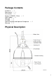
Package Contents IK-WP41A ---- 1 Allen wrench ---- 1 Torx wrench ---- 1 Screw (1/4-20UNC, 12mm) ---- 1 RJ45 Coupler ---- 1 Silica-gel ---- 1 CD-ROM ---- 1 Quick Start guide and Important Safeguards Warranty ---- 1 ---- 1 Physical Description Unit: mm 9
Hardware Installation First, use the supplied torx wrench to detach the dome cover from the camera housing. Then, follow the steps below to install the camera. NOTE: Installation should be done only by qualified personnel and conform to all local codes. The supplied torx wrench is exclusively designed to match the dome cover screws. Don’t discard the torx wrench 1. Packing material, Silica-gel and micro SD/SDHC Card 1.1 Packing material Two packing materials on the lens module are for shipping only.
Hexagonal screws Housing Lid (2) Attach a silica-gel Get out the supplied silica-gel from the aluminum foil bag, and set it as attached image. NOTE: Treat silica-gel bag with care, Don’t tear the silica-gel package. WARNING: Keep the silica-gel out of the reach of babies, infants, and children. DO NOT EAT, HARMFUL IF SWALLOWED (3) Attach a housing Lid Taking note of the arrowhead, attach a housing lid. Rotate counterclockwise, arrows are united.
2. Install to the mounting bracket IK-WP41A supports several mounting brackets like pendant mount, wall mount, etc. Select an appropriate bracket according to your location, and purchase separately. Here are major instance of installation. For more information about accessories, visit www.toshibasecurity.com. 2.1 Wall Mount (JK-WM41A) A) Drill 4 holes on the wall matching the mount holes on the plate. Diameter φ3/8” (9.5mm), depth 1/1/2” (39mm).
13
2.2 Wall Mount With Electrical Box (JK-WMB41A) A) Drill 4 holes on the wall matching the mount holes on the plate. Diameter φ3/8” (9.5mm), depth 1/1/2” (39mm) B) Hammer 4 anchor bolts (not supplied) into the holes and secure them. (Figure 1) C) Secure the electrical box to the wall with hex nuts and wrench (not supplied). (Figure 2) D) Loosen the screws of the lid with a supplied torx wrench in the bracket. (Note: Leave in a lower right screw shown in Figure 2.
Warning: The safety wire must be connected to the camera and wall mount bracket. This will avoid personal hazards if the unit falls from its installation. When installing the camera, secure the safety wire to the screw holes on the bracket. Make sure there are no damaged parts during assembly.
16
3. Cable connection No. Connector Descriptions For Ethernet connection. Connects this port to the LAN port of Ethernet switch via supplied coupler. 1 RJ-45 Connector 2 24V AC Power Input(Black/White) and Ground(Green) Connect the power terminals to a 24V AC power supply and ground the green wire. 3 Reset (Orange/White) Using a pointed object, short both terminals to restart the camera. 4 Audio In (Black/White) Connect to an external microphone to this terminal.
Alarm In 5 (Blue) 6 Alarm In 6 (Green) Connect to device that responds to alarm signals. Alarm In GND (White) 7 8 9 3.1 Alarm In 1 (Red) Alarm in 2 (Brown) Alarm In 3 (Yellow) Alarm in 4 (Orange) Default (Pink/Gray) Connect to device that triggers alarm signals. Connect to device that triggers alarm signals. Using a pointed object, short both terminals for about 5 seconds to restart the camera to the factory default.
3.2 Optional connection such as alarm in/out devices to the camera. Network Deployment 1. Connect the Camera to the Network Using an Ethernet cable (not supplied), connect one end to the RJ45 connector of the camera and the other end to the LAN port of the network switch via supplied RJ45 coupler. And connect your client PC to this network switch. 2. Install “IP Camera Finder” on your client PC To make the camera accessible to your network, you must configure appropriate network settings for the camera.
appear. Click the camera you want to configure the network settings. If you have multiple cameras connected to your local network, the MAC address on the camera to distinguish the target camera from others. Configure the following settings as needed. Name: Enter a descriptive name for the camera. Network Setting: If you have a DHCP server on your network to assign IP addresses to network devices, enable the DHCP option. Otherwise, manually enter the IP, Subnet Mask and Gateway settings.
Log-in Screen Double-Click the listed camera to login on the IP Camera Finder. Input the administrator log-in ID and password in the user name and password fields and click the OK button. The administrator log-in ID and password are set to "admin" and to "1234" respectively by default. Important Administrator Log-in allows rewriting of all settings. Be certain to change the administrator log-in ID and password already set in the camera by default, to ensure camera security.
Retrieving Images Retrieve live video through Internet Explorer®. A menu is shown if the menu button on a screen is clicked.
A camera control panel is shown if PTZ Control is clicked. A camera setup menu is shown if “Configuration” is clicked on the following screen. A live video of camera is shown if “Live Video” is clicked on the following screen.
TOSHIBA AMERICA INFORMATION SYSTEMS, INC.