I:\3207456121PCS1WW\01COV.FM masterpage:Sinistra 3-207-456-12 (1) Video Communication System Operating Instructions Before operating the unit, please read this manual thoroughly and retain it for future reference.
I:\3207456121PCS1WW\02REG.FM Owner’s Record The model and the serial numbers are located at the bottom. Record the serial number in the space provided below. Refer to these numbers whenever you call upon your Sony dealer regarding this product. Model No. PCS-1/1P Serial No. ______________ WARNING To prevent fire or shock hazard, do not expose the unit to rain or moisture. To avoid electrical shock, do not open the cabinet. Refer servicing to qualified personnel only. WARNING This unit has no power switch.
I:\3207456121PCS1WW\02REG.FM masterpage:Left Gooi de batterij niet weg maar lever deze in als klein chemisch afval (KCA). Lever het apparaat aan het einde van de levensduur in voor recycling, de batterij zal dan op correcte wijze verwerkt worden. If you dispose the unit, consult your nearest Sony Service Center. The built-in battery must be treated as a chemical waste. For the customers in Canada This Class A digital apparatus complies with Canadian ICES-003.
I:\3207456121PCS1WW\01COVTOC.FM masterpage:Left Table of Contents Chapter 1: Installation and Preparation Using This Manual ............................. 8 Features .............................................. 9 System Components ........................ 10 Basic System Components ......... 10 Optional Equipment ................... 11 System Configuration ...................... 13 System Configuration via a LAN ................................ 13 System Configuration via an ISDN ........................
I:\3207456121PCS1WW\01COVTOC.FM Registering a New Remote Party 52 Changing the Contents of the Phone Book ................................54 Deleting the Registered Remote Party ................................55 Copying the Setting of the Phone Book Menu ......................55 Chapter 3: Daily Videoconference Starting a Conference by Calling a Remote Party ....................................56 Turning on the Power .................56 Using the Launcher Menu ..........
I:\3207456121PCS1WW\01COVTOC.FM masterpage:Left Saving Still Images Using the Still Image Menu .................... 97 Saving Still Images Using the Memory Stick Menu ....... 98 Saving Still Images Using the Communication Submenu ......................... 99 Using a Convenient Menu Available during Communication — Communication Submenu .............. 100 Operating the System During a Conference .....................119 Displaying the Picture on a Projector or Monitor .....................................
I:\3207456121PCS1WW\01COVTOC.FM What is “Broadcast Mode”? ..... 143 Broadcast Modes and Displayed Windows ....................... 145 Switching the Broadcast Mode . 146 Receiving the Broadcast Requested From Any Other Terminal ........................ 147 Ending the Multipoint Videoconference ............................148 Notes on Secondary Terminals ...... 149 Connecting the External MCU .......150 Activating the Chair Control .... 150 Multipoint Attribute .......................
Chapter 1: Installation and Preparation Using This Manual The chapters cover the following contents; please read the chapters that may be required for your type of videoconference. Chapter 1: Installation and Preparation This chapter guides you through the system configuration and information required to use your Video Communication System for the first time. It shows you how to install and connect your Video Communication System, to turn the system on/off and how to access basic on-screen menus.
I:\3207456121PCS1WW\03OVR.FM masterpage:Left Wide range of video/audio compression format selectable The PCS-1/1P Video Communication System is a videoconferencing system that provides natural, face-to-face communications with a remote party by transmitting and receiving images and sound via LAN (Local Area Network) or ISDN (Integrated Services Digital Network) connections. The Video Communication System supports MPEG4, H.263+, H.263 and H.261 for video compression format, and MPEG4 Audio, G.722.1, G.
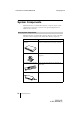
I:\3207456121PCS1WW\03OVR.FM masterpage:Left System Components The PCS-1/1P Video Communication System is composed of basic system components for a basic videoconference, and optional equipment for an enhanced videoconference. Basic System Components The PCS-1/1P Video Communication System is the basic system of the PCS1/1P Videoconferencing System.
I:\3207456121PCS1WW\03OVR.FM masterpage:Left Optional Equipment TV monitor Unit Description TV, Projector, etc. Used as a monitor and speakers. Optional equipment especially designed for use with the PCS-1/1P The following optional devices are used to enhance your videoconference. Unit Description PCS-B768 ISDN Unit Used to connect to an ISDN line. Up to six ISDN lines; 12B channels usable.
I:\3207456121PCS1WW\03OVR.FM masterpage:Left Unit Description PCS-DS150/DS150P Document Stand Allows transmission of pictures to the Communication Terminal by infrared signals without connecting a cable. PCS-323M1 H.323 MCU Software Allows use for a multipoint videoconference over LAN connection. PCS-320M1 H.320 MCU Software Allows use for a multipoint videoconference over ISDN connection. Connecting cables Use the following connecting cables to connect devices in this system.
I:\3207456121PCS1WW\03OVR.FM masterpage:Left System Configuration System Configuration via a LAN This allows you: • To hold a point-to-point videoconference over LAN. • To show still images stored in a “Memory Stick”.
I:\3207456121PCS1WW\03OVR.FM masterpage:Left System Configuration via an ISDN Connection to ISDN is required to use the PCS-B768 ISDN Unit especially designed for use with this system. This allows you: • To hold a point-to-point videoconference over ISDN. • To show still images stored in a “Memory Stick”. • To hold a videoconference with high speeds and highest quality image transmission by connecting up to six ISDN lines.
I:\3207456121PCS1WW\03OVR.FM masterpage:Left System Configuration via a LAN for Multipoint Conference You need to install the optional PCS-323M1 H.323 MCU software.
I:\3207456121PCS1WW\03OVR.FM masterpage:Left System Configuration via an ISDN for Multipoint Conference You need to connect the optional PCS-B768 ISDN Unit especially designed for use with this System and to install the optional PCS-320M1 H.320 MCU software. This allows you: • To hold a multipoint videoconference among up to six sites over ISDN. • To show still images stored in a “Memory Stick”. • To show the still images on the second TV monitor or projector.
I:\3207456121PCS1WW\03OVR.FM masterpage:Left System Configuration via a LAN for Multipoint Data Conference You need to connect the optional PCS-DSB1 Data Solution Box especially designed to use with this System and to install the optional PCS-323M1 H.323 MCU software.
I:\3207456121PCS1WW\03OVR.FM masterpage:Left System Configuration via an ISDN for Multipoint Data Conference You need to connect the optional PCS-B768 ISDN Unit and the PCS-DSB1 Data Solution Box especially designed for use with this System and to install the optional PCS-320M1 H.320 MCU software. This allows you: • To hold a multipoint videoconference among up to six sites over ISDN. • To show still images stored in a “Memory Stick”. • To use the data from a computer or an external equipment.
I:\3207456121PCS1WW\03OVR.FM masterpage:Left System Connections This section describes the typical system connections. Notes System Connection via a LAN PCS-C1/C1P Camera Unit TERMINAL VISCA OUT to TERMINAL Camera cable* PCS-P1/P1P Communication Terminal AUDIO OUT AUX1–VIDEO IN–AUX2 to CAMERA UNIT AUDIO IN CAMERA UNIT MIC ISDN UNIT (PLUG IN POWER) 1 2 WHITE BOARD (MIXED) 100BASE-TX 10BASE-T VIDEO OUT AUX MAIN– MONITOR– SUB RGB OUT DC 19.5V DSB IR OUT 1 2 to DC19.
I:\3207456121PCS1WW\03OVR.FM masterpage:Left System Connection via an ISDN Notes • Do not connect/disconnect the camera cable or the interface cable with the power on. Doing so may damage the Camera Unit, Communication Terminal or ISDN Unit. • Used with the PCS-B768 ISDN Unit for the first time, the Communication Terminal may automatically upgrade the software of the ISDN Unit. While the upgrading message is displayed on the monitor screen, be sure not to turn off the Communication Terminal.
I:\3207456121PCS1WW\03OVR.FM masterpage:Left Preparing the System Inserting Batteries into the Remote Commander Chapter 1: Installation and Preparation Most of the operations with the Video Communication System can be controlled with the supplied Remote Commander. 1 Remove the battery compartment cover. 2 Insert two size AA (R6) batteries (supplied) with correct polarities into the battery compartment. Caution Be sure to insert the batteries E side first.
I:\3207456121PCS1WW\03OVR.FM masterpage:Left • If battery leakage occurs, clean the battery compartment and replace all the batteries with new ones. Turning On/Off the TV Monitor Together With the Communication Terminal If you use a Sony TV, insert the IR repeater under the remote sensor of the TV. Once you set the IR repeater, the TV will turn on or go to standby together with the Communication Terminal when you press the "/1 button on the supplied Remote Commander.
I:\3207456121PCS1WW\03OVR.FM masterpage:Left Turning the System On/Off This section describes how to turn on or off the Communication Terminal. 1 Turn on the TV monitor. If the IR repeater is installed in the TV monitor, set the TV monitor to standby mode. The TV monitor will turn on simultaneously when the Communication Terminal is turned on. 2 Turn on the power of any other equipment to be used for the videoconference.
I:\3207456121PCS1WW\03OVR.FM masterpage:Left Notes • After the power is turned on, the camera moves automatically for trial operation. Be careful not to catch your finger. • If you use force to prevent the camera moving, it may not resume moving and not output a signal to the Communication Terminal. In this case, turn off the Terminal, and turn it on again.
I:\3207456121PCS1WW\03OVR.FM masterpage:Left Setting the Video Communication System to Standby Mode You can turn on the Video Communication System with the @/1 button on the Remote Commander if it is in standby mode. Display the launcher menu on the monitor screen, then press the @/1 button on the Remote Commander. The message “Power off?” appears on the monitor screen. 2 Press the B or b button on the Remote Commander to select OK, and press the PUSH ENTER button.
I:\3207456121PCS1WW\03OVR.FM masterpage:Left Turning Off To turn off the Communication Terminal follow the procedure below. 1 Set the power switch on the right side of the Communication Terminal to the off position (a). 2 Turn off the power of other equipment used for the videoconference. Note Set the power switch on the Communication Terminal off when the system will not be used for an extended period. While the power switch is off, you cannot receive a call from a remote party.
I:\3207456121PCS1WW\03OVR.FM masterpage:Left Displaying the Help Pressing the HELP button on the Remote Commander displays a balloon help or a help screen to guide most operations on the monitor screen. You can check the version of the Communication Terminal, versions of the connected optional equipment for exclusive use of this system, and the options installed in the Terminal by displaying the Machine Information menu on the monitor screen.
I:\3207456121PCS1WW\03OVR.FM Setting Up the System for the First Time — Initial Setup Wizard masterpage:Left 3 ISDN Setup Wizard When you turn on the Communication Terminal for the first time after installation and the self-diagnosis is completed, the setup wizard appears on the monitor screen. Register your local system data with the setup wizard using the Remote Commander. 1 Select the language used for the onscreen menus and messages in the Language Setup Wizard.
I:\3207456121PCS1WW\03OVR.FM masterpage:Left When you select Auto SPID (only for customers in the USA and Canada) You can automatically set up the Area Code and Local Number on this page, and SPID items in the SPID menu. Note For details on the SPID settings, see “SPID Setting for Customers in the USA and Canada” on page 47. When 2-6 ISDN lines are used, enter the telephone numbers in the B1 to F2 text boxes in addition to the A1 and A2 boxes.
I:\3207456121PCS1WW\03OVR.FM Note When you set “DHCP Mode” to “Auto”, the assigned IP address is shown in the launcher menu (page 57) or Machine Information menu (page 50). When you do not know how to set up the LAN configuration, contact your network administrator. 10Use the V, v, B or b button to select “Next”, then press the PUSH ENTER button. The message window for confirmation appears. 11Use the V, v, B or b button to select “Save”, then press the PUSH ENTER button.
I:\3207456121PCS1WW\03OVR.FM 3 masterpage:Left Press the V or v button to select the item you want to set or adjust, then press the PUSH ENTER button. The setting items are displayed. Setup Sound Priority Multipoint Mode Off Chapter 1: Installation and Preparation Video/Audio On Keep pressing the [MENU] button to show more detailed setup menus. Save Cancel 4 Press the V or v button to select the setting item you want, then press the PUSH ENTER button.
I:\3207456121PCS1WW\03OVR.FM masterpage:Left Menu Configurations The menus of this system configure as described below. For more detailed menu configurations, refer to “Menu Configuration” on page 183. Launcher menu Phone Book menu Phone Book RECENT Recent LAN Connect Phone Book TOKYO Bob John LAN ISDN ISDN OSAKA NEW YORK PARIS 0-9 A-I Dial J-S T-Z Menu Angle Adj. Show Help New Entry IP:0.0.0.
I:\3207456121PCS1WW\03OVR.FM Launcher menu masterpage:Left Connect Phone Book Dial Menu Angle Adj. For details on the Dial menu, see page 61. Show Help IP:0.0.0.0 Video:Main ISDN:012345678912 Audio:MIC(INT)+AUX Still Image menu Still Image The launcher menu appears when the Video Communication System is turned on or is displayed while it is not connected to a remote party. For details on the launcher menu, see page 57.
I:\3207456121PCS1WW\03OVR.FM Memory Stick menu masterpage:Left Setup menu (for the administrator) Memory Stick Setup The Memory Stick menu is used when you are using a “Memory Stick”. The menu is not displayed unless a “Memory Stick” is installed in the Communication Terminal. The menu appears when you select from the menu tabs displayed by selecting “Menu” in the launcher menu. For details on the Memory Stick menu, see pages 85 to 98.
I:\3207456121PCS1WW\03OVR.FM desired symbol. Pressing the 0 button also enables you to enter the symbol, –, “ or ”. Entering Characters This section explains how to enter the letters, numerals or symbols on the text box in the menu using the Remote Commander. ZOOM VIDEOINPUT SELECT DISPLAY CLEAR SYMBOL PinP FAR/NEAR BACK SPACE ALPHA/ NUM VIDEO INPUT SELECT (SYMBOL) button To delete a character Press the PinP (BACK SPACE) button. The last entered character is deleted.
I:\3207456121PCS1WW\04SET.FM Chapter 2: Registration and Setup for System Administrators masterpage:Left 2 The Setup menu for the administrator appears on the monitor screen. Setup This chapter describes the registration and settings to be carried out by the system administrator.The chapter is intended to be read by the system administrator. Before starting a conference, register the required information on the local terminals of the system using the Setup menu for administrator.
I:\3207456121PCS1WW\04SET.FM 5 After the setting is completed, use the V, v, B or b button to select “Save”, then press the PUSH ENTER button. The setting is saved, and the Setup menu is restored. To page up or down the selected menu Use the V, v, B or b button on the Remote Commander to select the Page box, then press the b button to advance the page and the B button to go back to the previous page. Dial Setup Menu The Dial Setup menu is used to set the attributes for dialing.
I:\3207456121PCS1WW\04SET.FM 56K: Selects when connecting a remote party in a region or country where the ISDN transmission rate is 56 Kbps. Note The system is set to connect an ISDN line at the transmission rate of 64 Kbps at the factory. However, some countries such as the USA or some regions may use the ISDN transmission rate of 64 Kbps and 56 Kbps. You may not communicate with such country or region with the transmission rate of 64 Kbps. In this case, set “Restrict” to “56K” before dialing.
I:\3207456121PCS1WW\04SET.FM masterpage:Left G.711 µ-law: Selects the format based on the G.711 µ-law standard. G.711 A-law: Selects the format based on the G.711 A-law standard. Page 3/4 Dial Setup Page: 3/4 Prefix-A Prefix-B Prefix-C Save Cancel When “Prefix” on Page 1 of the Dial Setup menu is set to “Prefix-A”, the line number prefixed by the prefix (dial number) registered in this box is dialed.
I:\3207456121PCS1WW\04SET.FM Number of Lines Selects the number of ISDN channels used to receive a call. You can select from among 1B, 2B, 3B, 4B, 5B, 6B, 8B and 12B channels. Restrict Selects the transmission rate of the ISDN lines when a call comes in. Auto: Selects when connecting a remote party via a normal ISDN line. 56 K: Selects when connecting a remote party in a region or country where 56 Kbps is used for the ISDN transmission rate.
I:\3207456121PCS1WW\04SET.FM Note masterpage:Left Page 1/2 When the remote videoconferencing system does not support the Audio Mode selected by the local site, the mode automatically switches to “G.711”. T.120 Data Selects whether you conduct a data conference via the T.120 standard using NetMeeting. On: Enables conduct of the T.120 data conference. Off: Disables conduct of the T.120 data conference. For details on the T.120 data conference, see “Conducting a Data Conference Using NetMeeting – T.
I:\3207456121PCS1WW\04SET.FM LAN Bandwidth Selects the bandwidth to be used when connected to a LAN. You can select from among 384 Kbps, 768 Kbps, 1024 Kbps, 1920 Kbps and “Other”. When “Other” is selected, a bandwidth value between 1 and 1920 Kbps can be entered. Restrict Selects the ISDN transmission rate when dialing or answering. Auto: Selects when connecting a remote party via a normal ISDN line.
I:\3207456121PCS1WW\04SET.FM Mic Select Selects the microphone to be used. Internal: Uses the built-in microphone. External: Uses the microphone connected to the Communication Terminal. DSB MIC: Uses the microphone connected to the Data Solution Box. DSB AUX IN: Used to expand future system capability. Echo Canceler Selects whether you use the echo canceler. Internal: Enables the built-in echo canceler. External: Uses the echo canceler of the external equipment connected.
I:\3207456121PCS1WW\04SET.FM Standby Mode Sets whether the Communication Terminal is set to standby mode if it is not operated for a specified period of time. On: Activates standby mode. Off: Deactivates standby mode. Standby Time Specifies the time that the system remains on before entering the standby mode. You can specify a time between 1 and 99 minutes. For details on standby mode, see “Standby Mode Function” on page 24.
I:\3207456121PCS1WW\04SET.FM Control by Far End When “Far End Camera Control” is set to “On” in the Dial Setup menu on the local party and in the Answer Setup menu on the remote party, you can temporarily reject the camera control command transmitted by the remote party. On: Accepts the camera control command. Off: Rejects the camera control command. Memory Stick Format Formats the “Memory Stick”. If you format the “Memory Stick”, all the data including the still images and Phone Book stored will be lost.
I:\3207456121PCS1WW\04SET.FM Page 1/7 Area Code Enter the area code to be used for the ISDN interface. Do not enter the first “0” number of your area code. ISDN Setup Page: 1/7 Country/Region ISDN USA Country/Region Code 1 Protocol National ISDN Save masterpage:Left Local Number Enter the telephone number (local number) to be used for the ISDN interface. Cancel Country/Region Selects the country or region where you use the Communication Terminal.
I:\3207456121PCS1WW\04SET.FM masterpage:Left SPID This item is used only for customers in the USA and Canada. NTI DMS-100 (Custom ISDN): Enter “1*11”. ISDN Setup For details, see “SPID Setting for Customers in the USA and Canada”. Page: 1/7 Country/Region Auto SPID This item is used only for customers in the USA and Canada. 1 Protocol National ISDN • The D1-F2 text boxes are shown on the next page (Page 7). Fill in the boxes depending on the lines you connect.
I:\3207456121PCS1WW\04SET.FM masterpage:Left ISDN Setup ISDN Setup Page: 2/7 Area Code Page: 6/7 SPID Local Number A1 408 9876543 A1 019876543001 A2 408 9876544 A2 019876544001 B1 B1 B2 B2 C1 C1 C2 C2 Save Cancel When you use the AT&T 5ESS (National ISDN) switch type You may enter the same or different numbers in two channels. 4 Note The SPID generally comprises 12 digits, including a 7 digit LDN (Local Directory Number).
I:\3207456121PCS1WW\04SET.FM Host Name Enter the host name. Auto: Detects the gatekeeper automatically and uses it. Gatekeeper Address Enter the gatekeeper address used when “Gatekeeper Mode” is set to “On”. User Alias Enter the user name (H.323 alias) to be registered in the gatekeeper. User Number Enter the user number (E.164 number) to be registered in the gatekeeper. Page 3/5 LAN Setup Page: 3/5 SNMP Mode IP address Enter the IP address. On Trap Destination Network Mask Enter the network mask.
I:\3207456121PCS1WW\04SET.FM Contact Enter information on the administrator of this terminal.
I:\3207456121PCS1WW\04SET.FM ISDN UNIT Version Displays the version of the connected PCSB768 ISDN Unit. DSB Version Displays the version of the connected PCSDSB1 Data Solution Box. DSP Version Displays the version of the built-in DSP (Digital Signal Processor) for audio/video codec. Option I/F Displays the optional connected equipment. None: No optional equipment is connected. ISDN UNIT: The PCS-B768 ISDN Unit is connected. DSB: The PCS-DSB1 Data Solution Box is connected.
I:\3207456121PCS1WW\04SET.FM setting status on the local system and those under “Decode” show the status on receiving. Audio Mode Shows the current audio compression format. Video Mode Shows the current video compression format. Note The audio compression and video compression formats used for communication with a remote party may differ from the settings in this menu, depending on the status of videoconferencing system on the remote site. Frame Rate Shows the maximum frame rate of motion pictures.
I:\3207456121PCS1WW\04SET.FM 3 masterpage:Left When “ISDN” or “ISDN (Telephone)” is selected in step 4 Enter the name of a remote party in the Index text box. For character input, see “Entering Characters” on page 35. 4 List Edit Index: Bob ISDN Select the line interface you are using to connect to a remote party with “Line I/F”. ISDN Number of Lines: 6B Save 1 Enter the telephone number of the remote party in the telephone number text box beside “A”.
I:\3207456121PCS1WW\04SET.FM 7 Use the V, v, B or b button to select “Save”, then press the PUSH ENTER button. The settings are registered in the Phone Book. To connect to the remote party without using BONDING If the videoconferencing system of the remote party is not equipped with the BONDING function, entering one telephone number does not allow you to connect all the line numbers used to connect to the remote party.
I:\3207456121PCS1WW\04SET.FM Deleting the Registered Remote Party Follow the procedure below to delete the remote party from the Phone Book. Open the Phone Book menu. 2 Use the V, v, B or b button to select the remote party to be deleted in the Phone Book menu, then press the PUSH ENTER button. The submenu appears. 3 Press the V or v button to select “Delete”, then press the PUSH ENTER button. The message “Delete List?” appears.
I:\3207456121PCS1WW\05OPE.FM masterpage:Left Chapter 3: Daily Videoconference This chapter describes how to conduct a videoconference from start to finish after the administrator has completed various registrations and settings for the system. The videoconference explained here is a point-to-point conference via a LAN connection or ISDN connection using the optional PCS-B768 ISDN Unit. For use of a “Memory Stick” or optional equipment, see Chapter 4.
I:\3207456121PCS1WW\05OPE.FM 3 masterpage:Left Set the power switch on the right side of the Communication Terminal to on (@). The Communication Terminal turns on after a while. POWER indicators (Lights in green.) Power switch Note After the power is turned on, the camera moves automatically for trial operation. Be careful not to catch your finger. Using the Launcher Menu The launcher menu is displayed on the monitor screen when the system is turned on or while it is not connected to a remote party.
I:\3207456121PCS1WW\05OPE.FM masterpage:Left 2 System indicators The indicators show the current status of the local camera by the icons or letters listed below. Indicator (icon) 58 Identification Description LAN status The indicator is shown in dark when the LAN is enabled to use, and in light when it is disabled. Multipoint mode Multipoint mode is activated. Memory Stick “Memory Stick” is inserted. ISDN status When the optional ISDN Unit is connected, the ISDN port in use is shown.
I:\3207456121PCS1WW\05OPE.FM Indicator (icon) Identification Description Audio: Audio input The selected audio input on the local system is shown. MIC (INT): Sound from the built-in microphone. MIC (EXT): Sound from an external microphone connected to the Communication Terminal. MIC (DSB): Sound from an external microphone connected to the optional PCSDSB1 Data Solution Box. MIC (AUX): Sound from an external microphone connected to the AUX IN jack on the optional PCS-DSB1 Data Solution Box.
I:\3207456121PCS1WW\05OPE.FM masterpage:Left Selecting the Video/Audio Quality Mode You can select whether priority for video/audio quality is given to still picture, motion picture or sound. 1 Press the V, v, B or b button on the Remote Commander to select “Menu” on the launcher menu, then press the PUSH ENTER button. You can also display the menu by pressing the MENU button on the Remote Commander. The Setup menu appears.
I:\3207456121PCS1WW\05OPE.FM 4 masterpage:Left Press the v button on the Remote Commander to select “Save”, then press the PUSH ENTER button. Setup Video/Audio Picture Priority Multipoint Mode Off Keep pressing the [MENU] button to show more detailed setup menus. Save Cancel The settings are saved. 5 Setup Video/Audio Picture Priority Multipoint Mode Off Keep pressing the [MENU] button to show more detailed setup menus. Save Cancel The screen returns to the launcher menu.
I:\3207456121PCS1WW\05OPE.FM masterpage:Left Dial Line I/F IP LAN A2 LAN Bandwidth B1 1024 Kbps B2 C1 C2 More Options Dial Save Note Pressing the number buttons on the Remote Commander opens the Dial menu, allowing direct entry of the IP address or the ISDN telephone number with the number buttons. 2 Use the V, v, B or b button to select “Line I/F”, then press the PUSH ENTER button. The submenu appears.
I:\3207456121PCS1WW\05OPE.FM masterpage:Left 1 Enter the IP address of a remote party to connect in the IP text box. Use the V, v, B or b button on the Remote Commander to select the IP text box, then press the PUSH ENTER button. Then enter the IP address with the number buttons on the Remote Commander. Enter the host name and domain name when using the DNS server in the IP text box (ex. host.domain).
I:\3207456121PCS1WW\05OPE.FM masterpage:Left • To delete the entered ISDN telephone number, press the DISPLAY (CLEAR) button on the Remote Commander. 2 Select the number of channels connected when setting up a call. Use the V, v, B or b button on the Remote Commander to select “Number of Lines”, then press the PUSH ENTER button. Press the V or v button to select the number of channels to be used when calling a remote party from the displayed submenu, then press the PUSH ENTER button.
I:\3207456121PCS1WW\05OPE.FM masterpage:Left To save the entered IP address or ISDN line number in the Phone Book Select “Save” with the V, v, B or b button, then press the PUSH ENTER button on the Remote Commander. The address or number you entered is saved in the Phone Book and the List Edit menu is displayed. For details on the List Edit menu, see “Registering a Remote Party – Phone Book” on page 52.
I:\3207456121PCS1WW\05OPE.FM 2 masterpage:Left Use the V, v, B or b button on the Remote Commander to select a remote party from the Phone Book, then press the PUSH ENTER button. The submenu appears. Phone Book RECENT Recent LAN TOKYO Bob John 0-9 A-I J-S T-Z LAN ISDN ISDN Dial OSAKA NEW YORK PARIS PARIS 0.0.0.0 Edit New Entry Copy Delete If the desired remote party does not appear, see “To search for a remote party in the Phone Book” on page 66.
I:\3207456121PCS1WW\05OPE.FM masterpage:Left Selecting the “0-9”, “A-I”, “J-S” or “T-Z” tab opens the submenu. When you select the desired number or letter from the corresponding submenu, the Phone Book lists the six party names which start with the selected number or letter.
I:\3207456121PCS1WW\05OPE.FM masterpage:Left Receiving a Call from a Remote Party Operations for answering a call differ depending on the setting of the answer mode. Auto answer mode The system automatically receives a call from a remote party and you can start conferencing. Although no operation is necessary to start, the picture on the local site will be displayed on the remote site screen even if you are not ready to begin.
I:\3207456121PCS1WW\05OPE.FM masterpage:Left Note See pages 71 to 84 to adjust the sound and picture during the conference. To receive a call in manual answer mode When you receive a call, the Communication Terminal rings and the message “Incoming call. Respond?” appears on the monitor screen. Press B or b to select “OK”, then press the PUSH ENTER button. The system is then connected.
I:\3207456121PCS1WW\05OPE.FM masterpage:Left Ending the Conference 1 Press the CONNECT/DISCONNECT ( Commander. / ) button on the Remote The message “Disconnect?” appears on the monitor screen. 2 Press the B or b button on the Remote Commander to select “OK”, then press the PUSH ENTER button, or press the CONNECT/DISCONNECT ( / ) button on the Remote Commander. The system is disconnected. Note The power of the Communication Terminal remains on even if the system is disconnected.
I:\3207456121PCS1WW\05OPE.FM masterpage:Left Adjusting the Sound Adjusting the Volume You can adjust the volume of the sound to be received from a remote party. Press the VOLUME + button on the Remote Commander to increase the volume, VOLUME – button to decrease it. The volume level indicator appears on the monitor screen. The indicator will automatically disappear if you do not operate the buttons for a certain time.
I:\3207456121PCS1WW\05OPE.FM masterpage:Left Synchronizing Audio and Video – Lip Sync Function During the conference a time lag may occur between the sound and picture to be sent to the remote party. When you set “Lip Sync” to “On” in the Audio Setup menu, the system adjusts to synchronize audio and video. However, this may delay transmission of audio synchronized with video. For the Lip Sync setting, see “Audio Setup Menu” on page 42.
I:\3207456121PCS1WW\05OPE.FM masterpage:Left Adjusting the Camera You can adjust the image shot by the local camera that is sent to the remote party to obtain the desired angle and size. During communication you can also control the camera on the remote site to adjust the image shot by the remote camera. Selecting the Camera to be Controlled Before adjustment, choose whether you control the local or remote camera. 1 Press the FAR/NEAR button on the Remote Commander. The Display Control menu appears.
I:\3207456121PCS1WW\05OPE.FM masterpage:Left Adjusting the Camera Angle and Zoom Determine the angle of view and the size of the picture to be displayed on the monitor screen by adjusting the angle and zoom. You can make adjustments in the monitor screen during communication and in the launcher menu when not in communication. You can also make adjustments using the Camera menu. To make adjustment during communication 1 Select the camera you want to adjust.
I:\3207456121PCS1WW\05OPE.FM masterpage:Left The color of the screen frame changes, then you can adjust the camera angle and zoom. Connect Phone Book Dial Menu Angle Adj. Show Help IP:0.0.0.0 Video:Main ISDN:012345678912 Audio:MIC(INT)+AUX Press the V, v, B or b button to adjust the camera angle so that the desired angle of view is obtained. 3 Use the ZOOM button to zoom in or out.
I:\3207456121PCS1WW\05OPE.FM masterpage:Left 4 Press the V, v, B or b button to adjust the camera angle so that the desired angle of view is obtained. 5 Use the ZOOM button to zoom in or out. Press the ZOOM T button to zoom in (to enlarge image), and the ZOOM W button to zoom out (to obtain wider range of image). 6 Press the PUSH ENTER button. Adjusting the Focus and Brightness Normally, the focus and brightness are automatically adjusted to obtain optimum levels. You can also adjust them manually.
I:\3207456121PCS1WW\05OPE.FM masterpage:Left To display the picture to fill the monitor screen To display the picture in full screen while the Camera menu is displayed, select “Adjustments”, then press the PinP button on the Remote Commander. To cancel the full screen mode, press the RETURN button or PinP button on the Remote Commander. To adjust the focus automatically Press the number button 0 on the Remote Commander. The “Auto Camera” indicator appears and the focus is automatically adjusted.
I:\3207456121PCS1WW\05OPE.FM 2 masterpage:Left Adjust the camera angle and zoom. Use the V, v, B or b button to adjust the camera angle, and ZOOM button to adjust the zoom. 3 Keep one of the number buttons 1–6 pressed or press the of the 1–6 buttons continuously. button and one The angle and zoom setting is stored in the selected number button, and the message “Registered to Preset number 1 (–6).” appears.
I:\3207456121PCS1WW\05OPE.FM masterpage:Left The FAR indicator is displayed on the monitor screen when the remote camera is selected. 5 Adjust the angle and zoom. Use the V, v, B or b button to adjust the camera angle, and ZOOM button to adjust the zoom. 6 Press the PUSH ENTER button. The setting is registered in the selected preset number.
I:\3207456121PCS1WW\05OPE.FM 3 masterpage:Left Press the V or v button to select the preset number (1-6) you want to recall, then press the PUSH ENTER button. Camera Preset Save 1 Preset Load 2 Adjustments 3 4 5 6 The setting of the preset number is recalled and the camera moves to the position of that setting. On backup The built-in lithium battery enables retention of the memories such as preset camera adjustments even if the Communication Terminal is turned off.
I:\3207456121PCS1WW\05OPE.FM masterpage:Left Selecting the Input Picture and Sound This section describes how to switch the picture displayed on the monitor screen, and how to switch the input picture and sound. Switching the Displayed Picture Between the Local and Remote Pictures 1 Press the FAR/NEAR button on the Remote Commander. The Display Control menu appears. 2 Use the V, v, B or b button on the Remote Commander to select “Near” or “Far” under “Display”.
I:\3207456121PCS1WW\05OPE.FM masterpage:Left Note While in communication you can switch the video input of the remote system by selecting “Far” in the Video Input Select menu. Video Input Select Near Far Main Main Main: Select the picture shot by the Camera. Object: Select the picture from the optional PCS-DS150/DS150P Document Stand. AUX 1: Selects the picture from the equipment connected to the VIDEO IN AUX 1 connector.
I:\3207456121PCS1WW\05OPE.FM masterpage:Left Switching the Picture Displayed on the TV Monitor Each press of the DISPLAY button on the Remote Commander switches the picture displayed on the monitor screen as follows: Picture shot by the local or remote camera DISPLAY button Still image transmitted or received Chapter 3: Daily Videoconference RGB picture Picture on a whiteboard Notes • A still image is displayed only when it has been transmitted or received.
I:\3207456121PCS1WW\05OPE.FM masterpage:Left Monitoring the Local Picture as a Window Picture – PinP Feature You can display the picture shot by the local camera on your monitor screen as a window picture (Picture-in-Picture). This function enables you to check how your own party is monitored on the remote site. To display the window picture Press the PinP button on the Remote Commander. The local picture is displayed as a window picture.
Chapter 4: Videoconference With Optional Equipment This chapter describes the various videoconferences using the optional equipment in addition to the components contained in the PCS-1/1P Video Communication System. To conduct a data conference using the optional PCS-DSB1 Data Solution Box, see Chapter 5. To conduct a multipoint conference, see Chapter 7.
I:\3207456121PCS1WW\06OPE.FM 2 masterpage:Left Open the Memory Stick menu. Press the MENU button on the Remote Commander to display the Setup menu, and select (Memory Stick) icon with the V or v button. Memory Stick 3 Use the V, v, B or b button on the Remote Commander to select the still image you want to display, then press the PUSH ENTER button. The submenu appears. Memory Stick 2 Send Load Delete Slide Show 4 Use the V or v button to select “Load”, then press the PUSH ENTER button.
I:\3207456121PCS1WW\06OPE.FM 2 masterpage:Left Use the V, v, B or b button on the Remote Commander to select a still image from which you want to start a slide show, then press the PUSH ENTER button. The submenu appears. Memory Stick 2 Send Load Delete Slide Show 3 Use the V or v button on the Remote Commander to select “Slide Show”, then press the PUSH ENTER button. The slide show starts. During communication with a remote party, the still images are transmitted to the remote party.
I:\3207456121PCS1WW\06OPE.FM masterpage:Left To delete a still image Display the Memory Stick menu, select the still image you want to delete, and press the PUSH ENTER button. Select “Delete” from the displayed submenu with the V or v button, then press the PUSH ENTER button. The selected still image is deleted from the “Memory Stick”. To remove the “Memory Stick” Push the “Memory Stick” and release your finger. The “Memory Stick” will come out a little, and you can then remove it.
I:\3207456121PCS1WW\06OPE.FM masterpage:Left For details on a slide show, see page 86. Note The image file to be sent will be saved to the directory “\DCIM\100MSDCF”. Save it in the directory with a file name as “NNNnnnnn.JPG”*.
I:\3207456121PCS1WW\06OPE.FM About a “Memory Stick” What is “Memory Stick”? “Memory Stick” is a new compact, portable and versatile IC (Integrated Circuit) recording medium with a data capacity that exceeds a floppy disk. “Memory Stick” is specially designed for exchanging and sharing digital data among “Memory Stick” compatible products. Because it is removable, “Memory Stick” can also be used for external data storage.
I:\3207456121PCS1WW\06OPE.FM Before using a “Memory Stick” Terminal Write-protect tab Labeling position Notes • Do not attach any other material than the supplied label onto the label space. • Attach the label so that it does not stick out beyond the labeling position. • Do not write forcefully on the “Memory Stick Duo” memo area. • Carry and store the “Memory Stick” in its case. • Prevent metallic objects or your finger from coming into contact with the metal parts of the connecting section.
I:\3207456121PCS1WW\06OPE.FM masterpage:Left Sending Motion Pictures as Still Images You can send motion pictures shot by the Camera or those output from the connected external equipment as still images. When you are sending pictures that contain lots of text, it is recommended that you send them as still images. The images become clearer than motion pictures and the texts are easy to read.
I:\3207456121PCS1WW\06OPE.FM masterpage:Left To stop “Continuous Send” Press the PUSH ENTER button on the Remote Commander. Select “Stop” from the displayed submenu with the V or v button, then press the PUSH ENTER button. To cancel still image display Press the PUSH ENTER button on the Remote Commander to display the submenu. Select “Clear” with the V or v button, then press the PUSH ENTER button.
I:\3207456121PCS1WW\06OPE.FM masterpage:Left Sending Motion Pictures Output from a Document Stand as Still Images During communication motion pictures output from the optional PCS-DS150/ DS150P Document Stand connected to the Communication Terminal can be frozen, and you can send a still image to the remote party. PCS-DS150/DS150P Document Stand (not supplied) To send a still image 1 Shoot the image you want to send with the Document Stand.
I:\3207456121PCS1WW\06OPE.FM masterpage:Left Sending Motion Pictures Input from an External Camera or Other Equipment as Still Images During communication a motion picture output from an external camera or VCR connected to the Communication Terminal can be frozen, and then sent to the remote party. External camera, VCR, etc. AUDIO OUT AUX1–VIDEO IN–AUX2 AUDIO IN CAMERA UNIT MIC (PLUG IN POWER) 1 2 XXXX WHITE BOARD (MIXED) 100BASE-TX 10BASE-T VIDEO OUT AUX MAIN– MONITOR– SUB RGB OUT DC 19.
I:\3207456121PCS1WW\06OPE.FM masterpage:Left Receiving Still Images from a Remote Party During communication you can receive still images of the pictures shot by the remote camera if “Far End Camera Control” items are set to “On” both in the Answer Setup menu on the answering site and the Dial Setup menu on the dialing site. 1 Open the Still Image menu. Press the MENU button on the Remote Commander to display the Setup menu, then select the (still image) icon with the V or v button.
I:\3207456121PCS1WW\06OPE.FM masterpage:Left Saving Still Images to a “Memory Stick” You can save the picture shot by the local camera or input picture from the connected equipment or the remote picture during conference in a “Memory Stick”. Saving Still Images Using the Still Image Menu 1 Insert the “Memory Stick” in which you are saving the images into the Memory Stick slot. 2 Open the Still Image menu.
I:\3207456121PCS1WW\06OPE.FM masterpage:Left When the write-protect tab on the “Memory Stick” is set to “LOCK” when you selected “Save” in step 4 The message “Memory Stick write-protected” appears and you cannot save the still image file. When the memory of the “Memory Stick” is full The message “Memory full.” appears and you cannot save the still image file.
I:\3207456121PCS1WW\06OPE.FM 4 masterpage:Left Use the V, v, B or b button on the Remote Commander to move the cursor to the last thumbnail, the “Memory Stick” “Save” thumbnail, then press the PUSH ENTER button. Memory Stick “Memory Stick” “Save” thumbnail Save The selected picture is saved to the “Memory Stick” and a thumbnail is created. Saving Still Images Using the Communication Submenu 1 During communication with the remote party press the PUSH ENTER button. The communication submenu appears.
I:\3207456121PCS1WW\06OPE.FM masterpage:Left Using a Convenient Menu Available during Communication — Communication Submenu During communication with a remote party, pressing the PUSH ENTER button on the Remote Commander opens the communication submenu. The communication submenu allows you to perform operations often used during communication only by selecting the item in the menu.
I:\3207456121PCS1WW\06OPE.FM masterpage:Left Using Two Monitors – Dual Monitor The Communication Terminal enables you to connect two monitors. One monitor can be used exclusively for monitoring motion pictures. (Dual Monitor system) To connect the second monitor Connect the second monitor to the VIDEO OUT MONITOR SUB or RGB OUT connector on the Communication Terminal.
I:\3207456121PCS1WW\06OPE.FM masterpage:Left Notes • When “Dual Monitor” is set to “Off”, still images will be displayed on the first monitor screen. • When “Dual Monitor” is set to “On”, the local picture is displayed on the second monitor screen while not in communication. To display the picture on the second monitor screen Set “Sub Monitor Out” to “VIDEO OUT” or “RGB OUT” in Page 1 of the General Setup menu. (See page 43.
I:\3207456121PCS1WW\06OPE.FM masterpage:Left Switching the Picture Displayed on Dual Monitors You can display the following pictures on the first or second monitor while in communication. Second monitor Local party First monitor Local party DISPLAY button Remote party Still image FAR/NEAR button Remote party RGB image Picture on a whiteboard First monitor • Enables display of motion pictures on the local or remote site.
I:\3207456121PCS1WW\06OPE.FM masterpage:Left Using Multiple Microphones The microphone built in the PCS-C1/C1P Camera Unit is assumed to be used to conduct a conference among about three participants. You can connect the optional PCS-A1 or PCS-A300 microphone to the System, allowing more persons to participate in the conference. To connect the optional microphones Connect the optional microphones to the MIC 1 and MIC 2 connectors on the Communication Terminal.
I:\3207456121PCS1WW\06OPE.
I:\3207456121PCS1WW\06OPE.FM masterpage:Left Recording Audio During a Conference You can record the voices of the participants on both the remote and local sites during a conference if you connect a video cassette recorder to the AUDIO OUT (MIXED) jack on the Communication Terminal. This is convenient for taking minutes of the conference. To connect a video cassette recorder Video cassette recorder, etc.
I:\3207456121PCS1WW\06OPE.FM masterpage:Left Sending Audio/Video from the External Equipment to a Remote Party The Communication Terminal allows you to send the picture and sound output from the connected equipment such as a VCR to the remote party. To connect the video equipment for input The Communication Terminal is equipped with two video inputs. VCR, etc.
I:\3207456121PCS1WW\06OPE.FM masterpage:Left When set to “AUX”, the sound from the external equipment is input and the sound from a microphone is deactivated. When set to “MIC + AUX”, both sounds are input.
I:\3207456121PCS1WW\06OPE.FM masterpage:Left Outputting Video Signals to External Equipment The Communication Terminal allows you to output the video signal to the connected external equipment such as a projector and VCR. To connect the external video equipment for output VCR, etc.
I:\3207456121PCS1WW\06OPE.FM masterpage:Left Conducting a Conference Without the Picture – Voice Meeting Using the PCS-1/1P Video Communication System, you can conduct a conference only through voices via a normal phone without connecting the videoconferencing system. (Voice Meeting) Basic connecting procedures are the same as those for videoconferencing. Conducting a voice meeting with a remote party not registered in the phone book Set “Line I/F” to “ISDN(Telephone)” in the Dial Setup menu.
I:\3207456121PCS1WW\06OPE.FM masterpage:Left Controlling the Remote System With the Tone Signal – DTMF Transmission The Video Communication System enables you to control the remote system connected by transmitting the tone signal (DTMF: Dual Tone Multi Frequency) assigned to the numbers for dialing (0-9, , ). 1 Press the button on the Remote Commander during communication. The DTMF menu appears on the monitor screen.
I:\3207456121PCS1WW\06OPE.FM masterpage:Left Conducting a Data Conference Using NetMeeting – T.120 Data Conference Connecting the Communication Terminal to the computer with NetMeeting* installed enables conduct of a data conference in compliance with the T.120 standard of the ITU-T Recommendation via the PCS-1/1P Video Communication System only when it is connected over ISDN. * NetMeeting is a registered trademark of Microsoft Corporation.
I:\3207456121PCS1WW\06OPE.FM masterpage:Left To connect to a computer via a hub Connect the Communication Terminal to a computer using the UTP straight cable. Computer TERMINAL VISCA OUT Hub AUDIO OUT AUX1–VIDEO IN–AUX2 AUDIO IN CAMERA UNIT MIC ISDN UNIT (PLUG IN POWER) 1 2 WHITE BOARD (MIXED) 100BASE-TX 10BASE-T VIDEO OUT AUX MAIN– MONITOR– SUB RGB OUT DC 19.
I:\3207456121PCS1WW\06OPE.FM masterpage:Left 3 Click “Calling” in the NetMeeting window on the computer of either a local or remote party. 4 Enter the IP address set for the Communication Terminal in the “Address” text box of the “Call to” dialog box. 5 Click “Call”. After a while the connection is completed. For details on how to operate, refer to the Help menu of the NetMeeting application. About the transmission rate The Communication Terminal supports the following transmission rates: MLP: 6.
I:\3207456121PCS1WW\06OPE.FM masterpage:Left Accessing the Communication Terminal The following controls are available to access the Communication Terminal. For details on each control, consult your Sony dealer. Using a Web Browser Accessing the IP address of the Communication Terminal from a Web browser allows you to control or set up the Terminal. For details on the password to access or Web monitoring feature, see “Administrator Setup Menu” on page 45.
I:\3207456121PCS1WW\07OPE.FM masterpage:Left Chapter 5: Data Conference This chapter shows you how to use the data from a computer, etc. connected to the optional PCS-DSB1 Data Solution Box for a conference. The optional PCS-DSB1 Data Solution Box is equipped with various input/ output connectors. For example, connecting the RGB output on a computer enables you to transmit the pictures or text data displayed on the computer to a remote party.
I:\3207456121PCS1WW\07OPE.FM masterpage:Left Connection Example Using the Data Solution Box Note • Be sure not to turn on the power of each unit until all the connections are completed. • Do not connect/disconnect the camera cable or the interface cable with the power on. Doing so may damage the Camera Unit, Communication Terminal or Data Solution Box. • Used with the Data Solution Box for the first time, the Communication Terminal may automatically upgrade the software of the Data Solution Box.
I:\3207456121PCS1WW\07OPE.FM masterpage:Left Notes on the connection example • Power to the Data Solution Box is supplied from the PCS-P1/P1P Communication Terminal with a connection described above. • Connect a projector, etc. to the RGB OUT connector on the Data Solution Box. This connection enables you: – To display the computer picture on the local site while transmitting it to the remote site. – To display the received computer picture with optimum picture quality.
I:\3207456121PCS1WW\07OPE.FM masterpage:Left Using Audio/Video Signal from the Connected Equipment for a Conference Setting Before Conferencing To use a microphone connected to the Data Solution Box Set “Mic Select” to “DSB MIC” in the Audio Setup menu (page 43). To use a projector, etc. connected to the RGB OUT connector on the Data Solution Box Set “Monitor Out (or Sub Monitor Out)” to “RGB OUT (DSB)” in Page 1 of the General Setup menu (page 43).
I:\3207456121PCS1WW\07OPE.FM masterpage:Left For details on picture quality, see “Picture quality of the data solution box” on page 120. SEND button RGB A RGB B RGB SELECT SEND RGB IN A RGB IN B Note While you are transmitting the computer picture, you cannot receive a still image or a computer picture from any other terminal. Ending your transmission enables you to receive it.
I:\3207456121PCS1WW\07OPE.FM masterpage:Left When the PCS-1/1P is used as a receiving terminal via LAN Setting of “Monitor Out (or Sub Monitor Out)” on the receiving terminal Output connector for a computer picture on receiving terminal Resolution Video frame rate Picture quality When “Dual Monitor” is set to “On” VIDEO OUT – VIDEO OUT MONITOR MAIN on the PCS-P1/P1P a a Outputs the signal by converting a transmitted VGA, SVGA or XGA signal into a 4CIF signal.
I:\3207456121PCS1WW\07OPE.FM Setting of “Monitor Out (or Sub Monitor Out)” on the receiving terminal When “Dual Monitor” is set to “Off” When “Dual Monitor” is set to “On” RGB OUT (DSB) RGB OUT (DSB) Output connector for a computer picture on receiving terminal RGB OUT on the PCS-DSB1 (only when the PCS-DSB1 is enabled) masterpage:Left Resolution Video frame rate Picture quality Outputs the signal by converting a transmitted VGA, SVGA or XGA signal into an XGA signal.
I:\3207456121PCS1WW\07OPE.FM masterpage:Left Displaying the Picture on a Projector or Monitor When you connect the Data Solution Box to the Communication Terminal, connections with external monitors, etc. using the following four outputs are available. The connections allow output of the picture to one or two monitors selected from among four.
I:\3207456121PCS1WW\07OPE.FM masterpage:Left RGB OUT (DSB): Outputs the signal to a monitor (Monitor D in the illustration above) connected to the RGB OUT connector on the Data Solution Box. Note When “Dual Monitor” is set to “Off” in the General Setup menu, output to a monitor connected to the VIDEO OUT MONITOR SUB connector is not available. When connecting the monitor to the RGB OUT connector on the Data Solution Box The menus may not be displayed.
I:\3207456121PCS1WW\07-2WB.FM masterpage:Left Chapter 6: Videoconference Using a Whiteboard This chapter describes how to use your whiteboard for your videoconferencing system. You can transmit and receive notes written on the whiteboard in real-time in a videoconference. You can also store the transmitted or received data in a Memory Stick as still images. Your whiteboard is usable for a videoconference only when the optional mimio Xi* is used together with the system.
I:\3207456121PCS1WW\07-2WB.FM masterpage:Left Connection Example With a Whiteboard Notes • Be sure to turn off all the equipment before making any connections. • Do not connect/disconnect the cable with the power on. Doing so may damage the Camera Unit, Communication Terminal or mimio Xi. Whiteboard TERMINAL AUDIO OUT AUX1–VIDEO IN–AUX2 AUDIO IN VISCA OUT CAMERA UNIT MIC ISDN UNIT (PLUG IN POWER) 1 2 WHITE BOARD (MIXED) 100BASE-TX 10BASE-T VIDEO OUT AUX MAIN– MONITOR– SUB RGB OUT DC 19.
I:\3207456121PCS1WW\07-2WB.FM masterpage:Left Conducting a Videoconference Using a Whiteboard ON LINE POWER LAN ALERT LAN or ISDN ON LINE ON LINE POWER ON LINE 1 POWER LAN ALERT LAN ALERT POWER LAN ALERT Start the videoconference. For the person who intends to send the whiteboard picture 2 Press the PUSH ENTER button on the Remote Commander to display the communication submenu on the monitor screen.
I:\3207456121PCS1WW\07-2WB.FM Local monitor screen 4 masterpage:Left Remote monitor screen Write anything using the stylus, marker or eraser that come with the mimio Xi on the whiteboard. The notes you are writing are displayed in real-time on the remote and local monitor screens. Whiteboard Monitors on the local and remote parties Notes • Only one whiteboard can be used at a time.
I:\3207456121PCS1WW\07-2WB.FM masterpage:Left To store the notes written on the whiteboard Display the communication submenu and then select “Save”. The whiteboard picture displayed on the monitor will be stored in the Memory Stick as a still image. Send Save Presentation START Whiteboard OFF Indicator OFF End To exit from the whiteboard mode The whiteboard user should open the communication submenu, select “Whiteboard OFF”, then press the PUSH ENTER button.
Chapter 7: Multipoint Videoconference This chapter describes how to conduct a multipoint videoconference. For conducting a multipoint videoconference, installation of the optional PCS-323M1 MCU software (for LAN connection) based on the H.323 standard or the optional PCS-320M1 MCU software (for ISDN connection) based on the H.320 standard is required. Multipoint videoconference among up to ten points including the local site is available when connecting via a LAN.
I:\3207456121PCS1WW\08OPE.FM masterpage:Left Connection Examples for a Multipoint Videoconference Using the LAN Connection (Up to 6 Points) Installing the optional PCS-323M1 H.323MCU software in one Communication Terminal allows you to conduct a multipoint videoconference among up to six points. PCS-323M1 H.
I:\3207456121PCS1WW\08OPE.FM masterpage:Left Using the Cascade Connection via LAN (Up to 10 Points) Installing the optional PCS-323M1 H.323MCU software in two Communication Terminals enables cascade connection, allowing you to conduct a multipoint videoconference among up to ten points. PCS-323M1 H.323 MCU software PCS-323M1 H.
I:\3207456121PCS1WW\08OPE.FM masterpage:Left Using the ISDN Connection Installing the optional PCS-320M1 H.320MCU software in one Communication Terminal allows you to conduct a multipoint videoconference among up to six points. PCS-320M1 H.320 MCU software TERMINAL AUDIO OUT AUX1–VIDEO IN–AUX2 AUDIO IN VISCA OUT CAMERA UNIT MIC ISDN UNIT (PLUG IN POWER) 1 2 PCS-B768 ISDN Unit WHITE BOARD (MIXED) 100BASE-TX 10BASE-T VIDEO OUT AUX MAIN– MONITOR– SUB RGB OUT DC 19.
I:\3207456121PCS1WW\08OPE.FM masterpage:Left Preparing for a multipoint videoconference Installing the MCU software Notes on installing the MCU software • You cannot install the software if the write-protect tab on the Memory Stick in which the MCU software is stored is set to “LOCK”. • Once the MCU software is installed in the Communication Terminal, the software will not be used again. • You cannot install the MCU software which is copied to another Memory Stick with a computer, etc.
I:\3207456121PCS1WW\08OPE.FM masterpage:Left Setting the Multipoint Setup Menu Before conducting a multipoint videoconference you need to set various items in the Multipoint Setup menu. Be sure to set “Multipoint Mode” to “On”.
I:\3207456121PCS1WW\08OPE.FM masterpage:Left Registering the Remote Parties in the Multipoint Connection List You can register the multipoint connection list that includes all remote parties for a multipoint videoconference in the Phone Book. It allows you to dial all the parties simultaneously. You can enter new remote parties to register the multipoint connection list, or add the parties registered in the Phone Book to the multipoint connection list.
I:\3207456121PCS1WW\08OPE.FM 3 Select the line interface icon or a still image to be displayed in the Phone Book. The icon is shown as “ 4 masterpage:Left LAN” or “ ISDN”. Set up the line interface of the remote parties. When “ LAN” is selected Select “LAN bandwidth” to be used and enter the IP addresses of all the parties. When “ ISDN” is selected Enter the telephone numbers of all the parties. To register a normal phone, enter the telephone number with “T” at the beginning. (e.g.
I:\3207456121PCS1WW\08OPE.FM masterpage:Left Number of registered points Phone Book RECENT Recent LAN TOKYO Bob 0-9 John A-I J-S T-Z LAN ISDN LAN OSAKA NEW YORK PARIS New Entry Multipoint mark Note To delete the mark from the name list, press the button again, or press the PUSH ENTER button to open the submenu, press the V or v button to select “ Off”, then press the PUSH ENTER button. 3 Select one of the remote parties with the ENTER button.
I:\3207456121PCS1WW\08OPE.FM masterpage:Left Starting a Multipoint Videoconference Calling Remote Parties To call remote parties registered in the multipoint connection lists 1 Select the multipoint connection list registered in the Phone Book. The multipoint connection lists are marked with “ 2 LAN” or “ ISDN”.
I:\3207456121PCS1WW\08OPE.FM 2 masterpage:Left Press the button on the Remote Commander, or press the PUSH ENTER button to open the submenu, press the V or v button to select “ On”, then press the PUSH ENTER button.
I:\3207456121PCS1WW\08OPE.FM masterpage:Left The system begins dialing the number of the remote party with the marks. “ Dialing (LAN)” or “ Dialing (ISDN)” appears on the monitor screen, and the ON LINE indicator (blue) on the Communication Terminal blinks. When the system connects to all the parties, the message “Meeting starts!” appears on the screen, and the ON LINE indicator stops blinking and lights.
I:\3207456121PCS1WW\08OPE.FM masterpage:Left The system begins dialing the numbers selected in step 3. “ Dialing (LAN)” or “ Dialing (ISDN)” appears on the monitor screen, and the ON LINE indicator (blue) on the Communication Terminal blinks. When the system connects to all the remote parties, the message “Meeting starts!” appears on the screen, and the ON LINE indicator stops blinking and lights.
I:\3207456121PCS1WW\08OPE.FM masterpage:Left Using the Display Control During a multipoint videoconference with the MCU software installed in the communication Terminal you can control the following operations. What is “Broadcast Mode”? You can use the “Split”, “Split (Fixed)”, “Voice Activate” and “Broadcast” modes. Split mode This mode allows display of the pictures from the connected remote terminals and the picture of the local terminal by splitting the monitor screen.
I:\3207456121PCS1WW\08OPE.FM masterpage:Left Split (Fixed) mode You can specify a picture among the split windows to fix it in the lower right window for the six-split mode. Pictures other than the specified one will be displayed in the split windows in order of connecting. Six-split window The picture of the specified terminal is always displayed in this window.
I:\3207456121PCS1WW\08OPE.FM masterpage:Left Broadcast Modes and Displayed Windows The chart described below shows the window displayed on the monitor screen when you select one of the Broadcast Modes. According to the connection status of your system, some modes cannot be selected. In the connection status with no window shown in the chart, the corresponding mode is not available.
I:\3207456121PCS1WW\08OPE.FM masterpage:Left Switching the Broadcast Mode At the beginning of the conference the mode set with “Broadcast Mode” in the Multipoint Setup menu is activated. You can switch the mode during communication. 1 Press the FAR/NEAR button on the Remote Commander. The Display Control menu appears. 2 Use the V, v, B or b button on the Remote Commander to select “Broadcast Mode”, then press the PUSH ENTER button.
I:\3207456121PCS1WW\08OPE.FM masterpage:Left To display the local picture in the Voice Activate mode You can display the local picture only on your monitor screen while the broadcast mode remains in Voice Activate mode. 1 Press the FAR/NEAR button on the Remote Commander. The Display Control menu appears. 2 Use the V, v, B or b button to select “Near” under “Display”, then press the PUSH ENTER button. The local picture appears on your monitor screen.
I:\3207456121PCS1WW\08OPE.FM masterpage:Left Ending the Multipoint Videoconference 1 Press the CONNECT/DISCONNECT ( Commander. / ) button on the Remote The following submenu appears. Phone Book Disconnect Dial Cancel 2 Use the V, v, B or b button to select “Disconnect”, then press the PUSH ENTER button. The screen changes to the split window screen and the following menu appears.
I:\3207456121PCS1WW\08OPE.FM Notes on Secondary Terminals If there is a terminal that is not adequate for the settings set by this system, that terminal is called the secondary terminal. Communication capabilities between the secondary terminal and this system are shown below. • Sending/receiving audio • Receiving video from the secondary terminal • Disables transmission of video to the secondary terminal For details on the secondary terminal, see Glossary on page 180.
I:\3207456121PCS1WW\08OPE.FM masterpage:Left Connecting the External MCU Connecting the external MCU (Multipoint Control Unit) enables conduct of a multipoint videoconference unless the MCU software is installed into the Communication Terminal.
I:\3207456121PCS1WW\08OPE.FM masterpage:Left The chair control is activated and you can control up to 99 terminals. The chair control feature is canceled if you set “Broadcast Mode” to “Chair Release”. Note When you operate incorrectly, the message “MCU operation rejected.” will appear on the monitor screen. Displaying the picture of the selected terminal 1 Open the Display Control menu. 2 Use the V, v, B or b button to select “Receive” under “Broadcast Mode”.
I:\3207456121PCS1WW\08OPE.FM masterpage:Left Exiting the chair control 1 Open the Display Control menu. 2 Use the V, v, B or b button to select “Chair Release” under “Broadcast Mode”. The chair control is not available for the local party.
I:\3207456121PCS1WW\08OPE.FM masterpage:Left Multipoint Attribute Number Attribute Value (H.320 MCU) Value (H.323 MCU) 1 Maximum number of terminals 5 (6 when including the that can be connected to a single local terminal) MCU 5 (6 when including the local terminal) 2 Maximum number of concurrent (independent) conferences that can be supported in a single MCU 1 1 3 Maximum number of ports that 0 can be connected to other MCUs 1 4.1 Network interfaces at each port BRI LAN 4.
I:\3207456121PCS1WW\08OPE.FM masterpage:Left Number Attribute Value (H.320 MCU) Value (H.323 MCU) 10 Method of choosing Selected Communication Mode - SCM Custom: Number of lines (1B/ 2B/4B/6B) Audio algorithm (G.711, G.728, G.722) Auto: Video frame rate (7.5/ 10/15/30fps) Video encoding mode (CIF/QCIF) Fixed or switched automatically: Video algorithm (H.261 fixed, H.261 or H.263 switched automatically) Restrict (56K fixed/ Auto) Custom: LAN bandwidth (Total rate of all points, max.
I:\3207456121PCS1WW\09OTH.FM masterpage:Left e Power switch Appendix Turns on/off the Communication Terminal. The power is on when the switch is set to the @ side and off when the switch is set to the a side. Location and Function of Parts and Controls f AUX CONTROL connector (D-sub 9-pin) Used for service.
I:\3207456121PCS1WW\09OTH.FM g MIC1/MIC2 (PLUG IN POWER) jacks (minijack) Connect to the optional PCS-A1 or PCSA300 microphone. Power is supplied to the microphone from the Communication Terminal. masterpage:Left p DSB connector (D-sub 15-pin) Connect to the TERMINAL connector on the optional PCS-DSB1 Data Solution Box. q DC 19.5V jack Connect the supplied PCS-AC195 AC power adaptor. h ISDN UNIT connector Connect to the TERMINAL connector on the optional PCS-B768 ISDN Unit.
I:\3207456121PCS1WW\09OTH.FM a Lens masterpage:Left PCS-R1 Remote Commander b Microphone c POWER indicator (green) Lights when the power switch on the Communication Terminal is set to on and goes out when it is set to off or the Terminal is set to standby mode. d Remote sensor Point the Remote Commander to the sensor when operating this System.
I:\3207456121PCS1WW\09OTH.FM c DISPLAY (CLEAR) button Switches the picture displayed on the monitor screen. Deletes a line when used for character input. masterpage:Left k VIDEO INPUT SELECT (SYMBOL) button Selects the video input signal. Each time you press the button, the input signal switches. Used to enter a symbol for character input. d PinP (BACK SPACE) button Displays a window picture when pressed during communication. Each time you press this button, the location of the window picture changes.
I:\3207456121PCS1WW\09OTH.FM masterpage:Left PCS-B768 ISDN Unit (Optional) PCS-DSB1 Data Solution Box (Optional) Front/Upper panel Front/Upper panel 1 1 2 3 4 5 1 2 RGB A RGB SELECT 6 3 RGB B SEND STATUS 2 1 2 3 4 5 RGB IN A RGB IN B 4 5 6 3 Rear LINE OUT Rear 6 4 a STATUS indicator Lights in orange when power is supplied to the ISDN Unit. When initializing is complete, blinks in green.
I:\3207456121PCS1WW\09OTH.FM masterpage:Left f LINE OUT jack (stereo minijack) Connect to the audio input jack on the active speaker, etc. Outputs monaural sound. g AUX IN/OUT jacks (phono jack) Used to audio input/output from/to external equipment. h MIC 1–MIC 5 jacks (minijack) Connect to the optional PCS-A1 or PCSA300 microphone. i TERMINAL connector (D-sub 15pin) Connect to the DSB connector on the Communication Terminal using the interface cable supplied with the Data Solution Box.
I:\3207456121PCS1WW\09OTH.FM masterpage:Left On Screen Messages Check the following if a message appears on the TV monitor when operating the Communication Terminal. Message Meaning Incorrect dialing setup. Make sure the selected entry is correctly registered. CANNOT COMPLETE CONNECTION (The following code and message appear.) — 0 Unknown network error: Try again later. 1 Number does not exist: Check the number and try again. 2,3,6 Network congestion: Try again later.
I:\3207456121PCS1WW\09OTH.FM Message masterpage:Left Meaning 180 Dialing your own number is invalid. Please check the IP address of the remote party. 181 GateKeeper error. Please check the IP address of the remote party. Busy line - Connection not possible. The telephone line of the remote party is busy and cannot be connected. Far end inactive The remote party operates the menu, and the still picture cannot be sent. System not responding. Check if the remote system is connected.
I:\3207456121PCS1WW\09OTH.FM masterpage:Left Message Meaning No Memory Stick. Insert a “Memory Stick”. Memory Stick write-protected. Release the lock of the erasure prevention switch on the “Memory Stick”. Memory full. The data has been saved in the “Memory Stick” to its full capacity. Memory Stick file error. The file format of the “Memory Stick” is incorrect or abnormal. Memory Stick file decode error. Decoding the JPEG file has failed. Memory Stick size error.
I:\3207456121PCS1WW\09OTH.FM masterpage:Left Message Meaning Connection with the Data Solution Box is not correct. Please reset the system. Connection between the Communication Terminal and the Data Solution Box is not correct. Turn off the Communication Terminal, then turn it on again. Fan in the Data Solution Box does not work properly. The Data Solution Box is not usable. The fan equipped with the Data Solution Box is not working properly. You cannot use the Data Solution Box.
I:\3207456121PCS1WW\09OTH.FM masterpage:Left Message Meaning The terminal has dropped out of the conference. The displayed terminal ends the multipoint videoconference. Viewing the terminal. [Terminal name] The picture of the displayed terminal can be seen on the screen. Now upgrading. Wait for a while. The software is now upgrading. Be sure not to turn off the Be sure not to turn off your system Communication Terminal until the upgrading is complete. while upgrading.
I:\3207456121PCS1WW\09OTH.FM masterpage:Left Troubleshooting If the Communication Terminal does not function correctly, check the following. Symptom Cause Solution The power is not turned on. The power switch is not set to on. Set the power switch to on (@) (page 23). The batteries in the Remote Commander are low or dead. Replace the batteries with new ones (page 21). The fan inside the Terminal stops. Turn off the system immediately and consult with Sony dealer.
I:\3207456121PCS1WW\09OTH.FM masterpage:Left Symptom Cause Solution No picture. The selected picture source is not tuned on. Turn on the selected video equipment. Video input is not selected properly. Select the video input with the VIDEO INPUT SELECT button (page 81). The selected picture source is not correctly connected to the System. No connection. Check the connections (page 107). A voice meeting is held. This is not a malfunction. Movement of the camera is prevented.
I:\3207456121PCS1WW\09OTH.FM masterpage:Left Symptom Cause No connection. Some of the system settings are not Set the system settings correctly correct. referring to “Registering Local Information” (page 36). Solution The IP address and network mask are not set correctly (when using LAN). Ask the system administrator to set them correctly (page 45). The LAN or ISDN cable is disconnected. Connect correctly (pages 19, 20). The LAN or ISDN cable is connected to the incorrect connector.
I:\3207456121PCS1WW\09OTH.FM masterpage:Left Symptom Cause No connection. Answering the call is not permitted Ask the remote party to permit by the remote terminal as it is answering a call. operating for setups, etc. Solution The remote terminal is not set to auto answer mode. Ask the remote party to set the terminal to auto answer mode, or to answer a call manually. The ISDN telephone numbers are not set up in the remote terminal (when using bonding).
I:\3207456121PCS1WW\09OTH.FM masterpage:Left 24 Kbps, 32 Kbps (G.722.1 compliant with ITU-T Recommendation) (when using LAN) 16 Kbps (G.728 compliant with ITU-T Recommendation) 8 Kbps (G.729 compliant with ITU-T Recommendation) (when using LAN) 5.3 Kbps, 6.3 Kbps (G.723.1 compliant with ITU-T Recommendation) (when using LAN) Specifications PCS-P1/P1P Communication Terminal This unit is compliant with ITU-T Recommendations H.320 and H.323.
I:\3207456121PCS1WW\09OTH.FM Storage humidity 20% to 80% (no condensation) Dimensions 258 × 54 × 171 mm (w/h/d) (10 1/4 × 2 1/4 × 6 3/4 inches) (not including the projected parts) Mass Approx. 1.3 kg (2 lb 14 oz) Supplied accessories Remote Commander PCS-R1 (1) Size AA (R6) batteries for Remote Commander (2) IR repeater (2) Camera cable (0.25 m, 0.8 ft) (1) S-video connecting cable (1.5 m, 4.9 ft) (1) Audio connecting cable (1 m, 3.
I:\3207456121PCS1WW\09OTH.FM PCS-A300 Microphone (Optional) Bandwidth 13 kHz Directional characteristic Unidirectional Dimension 68 × 16 × 96 mm (w/h/d) (2 3/4 × 21 /32 × 3 7/8 inches) Mass Approx. 200 g (7 oz) Power Plug in power PCS-B768 ISDN Unit (Optional) Power requirements 19.5 V Power consumption 0.
I:\3207456121PCS1WW\09OTH.FM masterpage:Left Acceptable RGB Input/Output Signals PCS-P1/P1P Communication Terminal (RGB OUT) Picture element Signal format 1024 × 768 fH (kHz) XGA VESA 60 Hz fV (Hz) 48.363 Dot clock (MHz) 60.004 Sync 65 H-neg V-neg PCS-DSB1 Data Solution Box (RGB IN A/RGB IN B) Picture element Signal format 640 × 480 VGA mode Macintosh 13” 800 × 600 1024 × 768 fH (kHz) fV (Hz) 31.469 Dot clock (MHz) Sync 59.94 25.17 H-neg V-neg 35 66.667 30.
I:\3207456121PCS1WW\09OTH.FM masterpage:Left PCS-DSB1 Data Solution Box (RGB OUT) Picture element Signal format 1024 × 768 XGA VESA 60 Hz fH (kHz) 48.363 fV (Hz) 60.004 Dot clock (MHz) Sync 65 H-neg V-neg • While the picture input from the RGB IN A or RGB IN B connector is transmitted, the picture of the input signal format (VGA, SVGA or XGA) is output from this connector.
I:\3207456121PCS1WW\09OTH.
I:\3207456121PCS1WW\09OTH.FM TERMINAL connector 8 1 15 9 D-sub 15-pin connector (female) masterpage:Left Pin Signal Description 9 19.5V 19.5V 10 NC – 11 AGND Analog ground 12 NC – 13 RD+ Transmit data+ 14 RD– Transmit data– 15 GND Ground Pin Signal Description 1 Y Brightness signal 2 Y.GND Brightness signal ground 3 C Chrominance signal 4 C.GND Chrominance signal ground 5 Video Video signal 6 Video.
I:\3207456121PCS1WW\09OTH.FM Pin Assignment on Optional Board Connectors ISDN 1-6 jacks (PCS-B768) 1 masterpage:Left Pin Signal Description 14 Ground GND TERMINAL connector (PCS-DSB1) 8 Modular jack 1 8 9 15 D-sub 15-pin connector (male) Pin Signal Description Pin Signal 1 NC – 1 Video Video signal 2 NC – 2 Video.
I:\3207456121PCS1WW\09OTH.FM Videoconferencing Room Layout masterpage:Left Side view (vertical range at maximum zoom-out) Be sure to position camera and microphone appropriately in your videoconferencing room. Camera Range 25˚ represents the shooting area of the camera when the zoom has been extended fully. indicates the shooting area of the camera when the left/right angling function is fully utilized. Use the measurements below as a guide for the layout of your videoconference room. 3.1 m (8.
I:\3207456121PCS1WW\09OTH.FM masterpage:Left Installing the Communication Terminal and Camera You can fix the Communication Terminal or the Camera to your chosen place of installation using the supplied Velcro. 1 Stick the supplied Velcro to the bottom of the Communication Terminal or Camera. Adjust room lighting so that it falls on the participants. Avoid direct light on the TV monitor. Light intensity on faces should be about 300 lux or more.
I:\3207456121PCS1WW\09OTH.FM Glossary BONDING* BONDING is one of the Inverse Multiplexing methods allowing connection of the videoconferencing system using multiple ISDN lines. Dialing the first ISDN line only enables you to connect all other lines. Dialing the second and later lines is automatically done by the communication between the videoconferencing systems on both sites.
I:\3207456121PCS1WW\09OTH.FM G.728 Audio encoding/decoding format recommended by the ITU-T. A phone bandwidth audio signal is converted to a digital signal with a data rate of 16 Kbps. Gatekeeper Controls the access of H.323 videoconference devices on a network. Administers the zone, access limitation, audio/video bandwidth, and alias etc. masterpage:Left An abbreviation for Inverse Multiplexer. This protocol allows you to transmit the data at 384 Kbps via 6B-channel.
I:\3207456121PCS1WW\09OTH.FM masterpage:Left Secondary terminal Normally, a multipoint videoconference is not available unless the video and audio modes and transmission rate of the videoconferencing systems of all the sites are the same.*1 For a multipoint videoconference the terminal that can be connected in the same modes is called a primary terminal, while a secondary terminal is the terminal in which some of the functions are restricted since the connection is not enabled with the same modes.
I:\3207456121PCS1WW\09OTH.FM masterpage:Left Menu Configuration The menus of the camera are configured as described below. For detailed information, see pages in parentheses. The initial settings of each item are bolded.
I:\3207456121PCS1WW\09OTH.FM A Dial Setup Page: 1/4 (page 37) Line I/F Bonding Number of Lines LAN Bandwidth Prefix Restrict B Answer Setup LAN, ISDN, ISDN (Telephone) Auto, On 1B, 2B, 3B, 4B, 5B, 6B, 8B, 12B 64Kbps, 128Kbps, 384Kbps, 768Kbps, 1024Kbps, 1920Kbps, Other (1–1920Kbps) Prefix-None, Prefix-A, Prefix-B, Prefix-C Auto, 56K Page: 2/4 Video Mode Video Frame Audio Mode Page: 3/4 Prefix-A Prefix-B Prefix-C Page: 4/4 Telephone Mode More Options Enable User Name Input Auto, G.711µ-law, G.
I:\3207456121PCS1WW\09OTH.FM C Multipoint Setup Page: 1/2 (page 41) Page: 2/2 D Audio Setup (page 42) E General Setup Multipoint Mode Broadcast Mode Number of Lines LAN Bandwidth Restrict On, Off Split, Voice Activate 1B × 5, 2B × 5, 4B × 3, 6B × 2 384Kbps, 768Kbps, 1024Kbps, 1920Kbps, Other (1–1920Kbps) Auto, 56K Video Mode Audio Mode Display Terminal Name Far End Camera Control ALL, H.263, H.261 ALL, G.722, G.728, G.
I:\3207456121PCS1WW\09OTH.
I:\3207456121PCS1WW\09OTH.
I:\3207456121PCS1WW\09OTH.FM Connection A* J Communication Status masterpage:Left (Encode) Audio Mode Video Mode Frame Rate LSD Rate MLP Rate HMLP Rate (Decode) Audio Mode Video Mode Frame Rate LSD Rate MLP Rate HMLP Rate Camera Control Data Control Line I/F Rate DSB Whiteboard (page 51) ... ...
Sony Corporation PCS-1/1P 3-207-456-12 (1)