Toshiba Personal Computer Satellite A80/A85 Maintenance Manual TOSHIBA CORPORATION [CONFIDENTIAL]
Copyright © 2004 by Toshiba Corporation. All rights reserved. Under the copyright laws, this manual cannot be reproduced in any form without the prior written permission of Toshiba. No patent liability is assumed with respect to the use of the information contained herein. Toshiba Personal Computer Satellite A80/A85 Maintenance Manual First edition September 2004 Disclaimer The information presented in this manual has been reviewed and validated for accuracy.
Preface This maintenance manual describes how to perform hardware service maintenance for the Toshiba Personal Computer Satellite SATELLITE A80/A85, referred to as the A80/A85 Series in this manual. The procedures described in this manual are intended to help service technicians isolate faulty Field Replaceable Units (FRUs) and replace them in the field. SAFETY PRECAUTIONS Four types of messages are used in this manual to bring important information to your attention.
The manual is divided into the following parts: Chapter 1 Hardware Overview describes the A80/A85 Series system unit and each FRU. Chapter 2 Troubleshooting Procedures explains how to diagnose and resolve FRU problems. Chapter 3 Test and Diagnostics describes how to perform test and diagnostic operations for maintenance service. Chapter 4 Replacement Procedures describes the removal and replacement of the FRUs.
Conventions This manual uses the following formats to describe, identify, and highlight terms and operating procedures. Acronyms On the first appearance and whenever necessary for clarification acronyms are enclosed in parentheses following their definition. For example: Read Only Memory (ROM) Keys Keys are used in the text to describe many operations. The key top symbol as it appears on the keyboard is printed in boldface type.
vi [CONFIDENTIAL] Satellite A80/A85 Maintenance Manual
Table of Contents Chapter 1 Hardware Overview 1.1 Features ............................................................................................................................ 1-1 1.2 System Unit...................................................................................................................... 1-5 1.3 2.5-inch Hard Disk Drive................................................................................................. 1-9 1.4 Removable Drives...........................
Chapter 3 Tests and Diagnostics 3.1 The Diagnostic Test .........................................................................................................3-1 3.2 Executing the Diagnostic Test..........................................................................................3-2 3.3 Config Check Test............................................................................................................3-6 3.4 DMI Check Test ...........................................................
Chapter 4 Replacement Procedures 4.1 General............................................................................................................................. 4-1 4.2 Battery.............................................................................................................................. 4-7 4.3 PC Card............................................................................................................................ 4-9 4.4 HDD........................................
Appendices Appendix A Handling the LCD Module..................................................................................A-1 Appendix B Board Layout....................................................................................................... B-1 Appendix C Pin Assignments .................................................................................................. C-1 Appendix D Keyboard Scan/Character Codes.........................................................................
Chapter 1 Hardware Overview 1 [CONFIDENTIAL]
1 Hardware Overview 1-ii [CONFIDENTIAL] Satellite A80/A85 Series Maintenance Manual
1 Hardware Overview Chapter 1 Contents 1.1 Features ...................................................................................................................... 1-5 1.2 System Unit................................................................................................................ 1-9 1.3 2.5-inch Hard Disk Drive......................................................................................... 1-11 1.4 Optical device Drives...............................................
1 Hardware Overview Figures Figure 1-1 2.5-inch HDD .............................................................................................. 1-11 Table Table 1-1 Table 1- 2 Table 1- 3 Table 1- 4 1-iv 2.5-inch HDD specifications ....................................................................... 1-11 DVD-ROM & CD-RW drive specifications ............................................... 1-12 DVD Super Multi drive specifications............ Error! Bookmark not defined.
1.1 Features 1.1 1 Hardware Overview Features The Satellite A80/A85 Series Personal Computer uses extensive Large Scale Integration (LSI), and Complementary Metal-Oxide Semiconductor (CMOS) technology extensively to provide compact size, minimum weight and high reliability. This computer incorporates the following features and benefits: CPU • Intel Celeron M CPU 350J (1.3GHz) / 360J (1.4GHz) / 370(1.5GHz), 0.
1 Hardware Overview Power • 1-6 4 cells Li-Ion 18650 size smart battery Pack with 14.4 Vx2000mAh • 8 cells Li-Ion 18650 size smart battery Pack with 14.4 Vx4300mAh HDD • 9.5mm, 2.5" HDD up to 120 GB • Bus Master IDE • 9.5m/m, 2.5”HDD Support • Support Ultra 100 synchronous DMA Fixed Device Drivers • Fixed bay • CD-RW/DVD-ROM, DVD-RAM/-R/-RW readable • DVD Super Multi Dual-Layer Recording: • 5/8/4/8/4/2.4x (write speed of DVD-RAM/-R/-RW/+R/+RW/+R DL) Optional Devices • 1.
1.1 Features 1 Hardware Overview Display • 15.0” TFT screen with a resolution of 1024 horizontal x 768 vertical pixels XGA I/O Ports • One 15 pins CRT port • One MIC In port • One headphone-out • One 2pins AC Adapter Jack • One type II PCMCIA Card Bus slots with shutter door • Three 4 pins USB 2.
1 Hardware Overview 1.1 Features PCMCIA Card Organization • One type II card sockets • 1.8" 10.5mm removable ATA Device • Card bus card or PC Care with hot insertion and removal • ACPI 1.1 Compliant. • Support 5V/3.3V PC Cards and 3.3V Cardbus cards. • Supports PCMCIA-ATA Specification. Universal Serial Bus (USB) The computer has three Universal Serial Bus (USB) ports that comply with the USB 2.0 standard, which enable data transfer speeds more than 40 times faster than USB 1.
1.2 System Unit 1.2 1 Hardware Overview System Unit The system unit is composed of the following major components: Processor • Intel Celeron M CPU up to 1.5GHZ 0.09u, 1M L2, FSB 400MHz • Micro FC-PGA package CPU System Logic • ATI RL300MB (400 MHz FSB supported) • ATI IXP150 • ENE KB910 for Keyboard Controller, Battery management Unit, and RTC. • TI PCI1410 for Card Bus PCMCIA controller. • Integrated VGA solution for RL300MB • Realtek ALC250VD for AC97 Codec.
1 Hardware Overview 1-10 1.2 System Unit Audio subsystem • Support of S’PDIF out is fully compliant with AC’97 rev2.3 specifications. • 20-bit Stereo Digital-to-Analog Converters. • 18-bit Stereo Analog-to- Digital Converters. • Built-in 7 Bands of Digital Hardware Equalizer for Optimizing Speaker Response. • Supports double sampling rate(96KHz) of DVD audio playback. • Two Analog Line-level Stereo inputs with LIN_IN, CD, and AUX. • Two Analog Line-level Mono Input: PCBEEP, PHONE-IN.
1.3 2.5-inch Hard Disk Drive 1.3 1 Hardware Overview 2.5-inch Hard Disk Drive The internal HDD is a random access non-volatile storage device. It has a non-removable 2.5inch magnetic disk and mini-Winchester type magnetic heads. The computer supports up to100GB HDD. The HDD is shown in Figure 1-1. Specifications are listed in Table 1-1 Figure 1-1 2.
1 Hardware Overview 1.4 1.4 Optical device Drives Optical device Drives • • DVD-ROM & CD-RW drive DVD Super Multi drive 1.4.1 DVD-ROM & CD-RW The DVD Super Multi drive accepts 12-cm (4.72-inch) and 8-cm (3.15-inch) discs. At maximum, the drive can play back a DVD at 8x speed, read CD-ROM at 24x speed, and write CD-R at 24x speed and CD-RW at 4x speed or High speed CD-RW at 10X or Ultra speed CD-RW at 24X speed. The specifications of the DVD-ROM & CD-RW drive are listed in Table 1-2.
1.4 Optical device Drives 1 Hardware Overview 1.4.2 DVD Super Multi Double Layer The DVD Super Multi drive accepts 12-cm (4.72-inch) and 8-cm (3.15-inch) discs. At maximum, the drive can play back a DVD at 8x speed, read CD-ROM at 24x speed, and write CD-R at 24x speed and CD-RW at 4x speed or Ultra and High speed CD-RW at 10x speed and DVD-R at 8x speed and DVD-RW at 4x speed and DVD+R at 8x speed and DVD+RW at 4x speed and DVDRAM at 5x speed and DVD+R DL at 2.4x speed.
1 Hardware Overview 1.5 1.5 Power Supply Power Supply This specification defines the performance and characteristic of 65W and 75W AC adapter power supply. It supplies a constant voltage 19V output source for A80/A85 series notebook computer.
1.5 Power Supply Battery charging control • The EC detects the low battery point by the gas gauge. – LB10M = The system will be driven by the battery for 12 more minutes. – LB0 = The battery won't be able to drive the system after 3 minutes. – LB1 = The battery can drive the system only during the suspend process. – LB2 = The battery cannot drive the system. New battery installation • The EC controls the following.
1 Hardware Overview 1.6 1.6 Batteries Batteries The computer has two types of battery: Main battery pack (18650 size) RTC battery The removable main battery pack is the computer’s main power source when the AC adaptor is not attached. The battery specifications are listed in the table below. Battery name 1-16 Material Output voltage Capacity Main battery (4 cell) Lithium-Ion 14.4 V 2000mAH Main battery (8 cell) Lithium-Ion 14.4 V 4300mAH RTC battery Lithium 3.
1.6 Batteries 1 Hardware Overview 1.6.1 Main Battery Battery charging is controlled by a power supply microprocessor that is mounted on the system board. The power supply microprocessor controls whether the charge is on or off and detects a full charge when the AC adaptor and battery are attached to the computer. The system charges the battery using quick charge or trickle charge.
1 Hardware Overview 1.6 Batteries 1.6.2 RTC battery The RTC battery provides power to keep the current date, time and other setup information in memory while the computer is turned off. The table below lists the charging time and data preservation period of the RTC battery. The RTC battery is charged by the adaptor or main battery, while the computer is powered on.
Chapter 3 Tests and Diagnostics 3 [CONFIDENTIAL]
Contents 3.1 The Diagnostic Test .........................................................................................................3-3 3.2 Executing the Diagnostic Test..........................................................................................3-4 3.3 Config Check Test............................................................................................................3-8 3.4 DMI Check Test ....................................................................................
The Diagnostic Test This chapter explains how to use the Test & Diagnostic program to test the functions of the (Base on Sakhir10E T&D version 1.0) hardware modules. The Test & Diagnostic Program is stored on the T&D diskettes. The program consists of a series of tests that run automatically when the Diagnostics Program items are selected and executed. NOTES: To start the diagnostics, follow these steps 1. Check all cables for loose connections. 2. Exit this program when you are at Main Menu.
3. Tests and Diagnostics 3.1 3.2 Executing the Diagnostic Test Executing the Diagnostic Test Toshiba MS-DOS is required to run the DIAGNOSTICS PROGRAM. To start the DIAGNOSTIC PROGRAM, follow these steps: 1. Insert the diagnostics diskette #1 in the floppy disk drive and turn on the computer. (The diagnostics diskette contains the MS-DOS boot files.) And then follow the instructions to swap with the diagnostics diskette #2 for T&D program installed in RAM driver.
3.2 Executing the Diagnostic Test 3.
3. Tests and Diagnostics 3.2 Executing the Diagnostic Test If an error is detected and a test fails, the following message displays: Then press any key for next actions – the below display presented if copying test log file onto diskette is necessary. This action will be executed when “Y” key pressed.
3.2 Executing the Diagnostic Test 3. Tests and Diagnostics It will skip this process if “N” key pressed. And then it will check if it’s necessary to leave this program. Program will quit when “Y” key pressed and it will go back main menu for next test if “N” key pressed. NOTE: Press Pause to pause a test and Enter to resume.
3. Tests and Diagnostics 3.2 3.7 Speaker Audio Test Config Check Test The config check test checks unit configuration. It includes: CPU type (P4/CEL; Dothan; Cache ; CPU speed ) BIOS version Panel ID VRAM size System memory size (*** MB) ODD type (DVD-SuperMulti; COMBO; …) HDD type & capacity (Vendor ID. Model .
3.7 Speaker Audio Test 3.3 3. Tests and Diagnostics DMI Check Test This test will check if the computer’s Desktop Management Interface (DMI) is correct. DMI includes: Manufacturer Production Name Version Serial Number UUID OEM String It needs to input unit Part Number by manual, then show this unit DMI information and makes comparison with SKU data. NOTE: To execute this test, you must input unit Part Number as “Uppercase Character”.
3. Tests and Diagnostics 3.7 Speaker Audio Test The screen should display as below, indicating whether the test is passed or failed after comparison. 3.4 speaker Audio Test The speaker audio test allows the user to aurally confirm the speaker functions. And check both speakers if they are OK within 3 times “Beep” sound generated. NOTE: Remember to tune up the volume as “Maximum” before this test starts.
3.7 Speaker Audio Test Satellite A80/A85 Series Maintenance Manual 3.
3. Tests and Diagnostics 3.5 3.8 Fan ON/OFF Test Fan ON/OFF Test The fan test allows the user to test aurally whether the fan is working. And follow the below procedures for this test: The computer will let the fan be “ON” after any key pressed. Listen to check whether the fan is working. NOTE: Remember to approach fan outlet that is near right side of unit whether fan is “ON”. The computer will stop the fan working after any key pressed.
3.9 Main Battery Change Test 3.6 3. Tests and Diagnostics Main Battery Charge Test NOTE: The AC adaptor (75W, 19V) should be connected to successfully run this test. This test shows and measures the main battery: Battery type (Lion) Manufacturer (Sanyo/Panasonic) Remain charge capacity (0 ~ 100%) Charge function (PASS/FAIL) - “Battery Is Full” showed when “remain charge capacity” is 100% The screen should display as below, indicating whether the test is passed or failed when finished.
3 Tests and Diagnostics 3.7 3.10 FDD Test FDD Test NOTE: Before running the FDD test, prepare a formatted work diskette (1.44 MB). Remove the diagnostics diskette and insert the work diskette into the FDD. The contents of the floppy diskette maybe erased. The Floppy Disk Test includes three subtests of the: 1. Sequential seek/verify function (Range: Track 0 ~ 79) 2. Funnel code seek/verify function (Range: Track 0 ~ 79) 3.
3.11 CD-ROM Test 3.8 3 Tests and Diagnostics ODD Test The ODD test allows a user to aurally confirm the CD-ROM functions. NOTE: A CD disc (including data file) must be inserted into the ODD drive before this test starts. The CD-ROM test includes two subtests of the: 1. Random read/partial sequential read function 2. Sequential read function (for all surface) Each item can be chosen by manual. When each test item finished, the CD-ROM tray will open. Check whether the tray can open automatically.
3. Tests and Diagnostics 3.9 3.12 Keyboard Test Keyboard Test The keyboard test checks the all keys function. NOTE: The Num Lock and the Overlay mode must be off to execute the keyboard test. Before keyboard test starts, the keyboard matrix code should be chosen as below display: 1. K (UK, for Europe) 2. S (US, for America) 3. J (JP, for Japan) When you execute this test, the keyboard layout is drawn on the display.
3.12 Keyboard Test Satellite A80/A85 Series Maintenance Manual 3.
3. Tests and Diagnostics 3.12 Keyboard Test p 9 Pressing a key also reveals that key’s scan codes in the upper right hand corner of the screen. When the key is depressed, its make code is displayed. When the key is released, the break code is shown.
3.13 Mouse (Pad) Test 3. Tests and Diagnostics 3.10 Mouse (Pad) Test The Mouse test allows the user to select and assign values to the following, using the Touch Pad or “Tab” key to move between selections: 1. Mouse Speed (on a scale from slow to fast) 2. Acceleration (Off, Low, Medium, High) 3. Button Assignments (Left + Right / Right button, either Unassigned or Drag Lock) 4. Swap Buttons (Left /Right) NOTE: The Touch Pad test cannot be used to test an external USB mouse.
3. Tests and Diagnostics 3.13 Mouse (Pad) Test After checking T/Pad buttons and cursor’s function, use “Tab” key or use T/Pad cursor to click the “OK” column will end this test. It will indicate whether the subtests pass or fail after three questions. NOTE: The above figure has three compartments although the Touch Pad installed may only have two buttons. In this case, the central compartment in the figure does not correspond to any button.
3.14 LCD Pixels Mode Test 3. Tests and Diagnostics 3.11 LCD Pixels Mode Test This LCD pixels mode test checks whether video display is fine. This test includes two modes of the test: 1. Text Mode - including 40*25 (16 colors) and 80*25 (2/16colors). 2. VGA Mode - including 320*200 (4/16/256 colors), 640*200 (2/16 colors), 640*350 (2/16 colors), 640*480 (2/16/256 colors), 800*600 (256 colors) and 1024*768 (256 colors).
3. Tests and Diagnostics 3.15 Lid Switch Test 3.12 Magnetic Lid Switch Test The lid switch test checks the lid function of the unit. When LCD cover closed, the lid should enable to turn off the display. NOTE: Remember to tune up the volume as “Maximum” before this test starts. Follow below steps to run this test: 1. Close the LCD cover. 2. Heard 3 “Beep” sound happened during LCD closed. 3. Open the LCD. Then it will indicate whether the test is passed or failed.
3.16 HDD R/W Test 3. Tests and Diagnostics 3.13 HDD R/W Test The HDD R/W test allows the user to test aurally HDD read/write function. For data security concern, it is necessary to input password - “hard disk” before HDD write test starts. The HDD test includes three subtests of the: 1. Sequential read (all surface) 2. Sequential write (all surface) 3.
3. Tests and Diagnostics 3.16 HDD R/W Test NOTE: Press “Ctrl + Break” keys can terminate the current subtest. The screen should display as previous picture, indicating whether the subtest is passed or failed when finished. NOTE: The AC adaptor should be connected to successfully run this test.
3.17 LAN Test 3. Tests and Diagnostics 3.14 LAN Test The LAN test checks the LAN full-duplex environment. NOTE: LAN loopback needs to plug in before test begins. And LAN information will show on the test screen: IO Base – Port: 3000H IRQ – AH, it’s “IRQ 10”. Node – it is “MAC Address”. Line Frame – 1514 Bytes. Line Speed – 100Mbps or 10 Mbps. Bus ID – it’s “4”. The LAN test includes two subtests of the: 1. Speed100 - including Ethernet_802.
3. Tests and Diagnostics 3.17 LAN Test The screen should display as below, indicating whether the subtests pass or fail when finished.
3.18 RTC Test 3. Tests and Diagnostics 3.15 RTC Test Checks the computer’s RTC (Real Time Clock) and calendar functions by comparing the DOS and CMOS values. The test runs automatically. The screen should display as below, indicating whether the test is passed or failed when finished.
3. Tests and Diagnostics 3.19 CD Control Button Test 3.16 CD Control Button Test The CD control button test allows the user to manually test each of the five CD control buttons. Key ”WWW” need to press first. One will hear one “bi” sound when press ”WWW” or “Audio” Sound, and continuously “bi” sound for another key test. The figure below will be displayed: Press each of the buttons on the front panel in turn. A yellow bar will appear on the relevant section of the figure if the button passes the test.
Chapter 4 Replacement Procedures 4 [CONFIDENTIAL]
4 Replacement Procedures 4-ii [CONFIDENTIAL] Satellite A80 /A85 Series Maintenance Manual
4 Replacement Procedures Chapter 4 Contents 4.1 General............................................................................................................................. 4-1 4.2 Battery.............................................................................................................................. 4-7 4.3 PC Card............................................................................................................................ 4-9 4.4 HDD............................
4 Replacement Procedures Figures Figure 4-1 Removing the battery pack ...................................................................................4-7 Figure 4-2 Removing a PC Card.............................................................................................4-9 Figure 4-3 Installing a PC Card ............................................................................................4-10 Figure 4-4 HDD .............................................................................
4 Replacement Procedures Figure 4-26 Removing the Direct Play Button board ............................................................ 4-31 Figure 4-27 Removing the Memory Module ......................................................................... 4-32 Figure 4-28 Removing the Touch Pad board ......................................................................... 4-33 Figure 4-29 Removing the speakers.......................................................................................
4 Replacement Procedures 4.1 General This chapter explains how to disassemble the computer and replace Field Replaceable Units (FRUs). It may not be necessary to remove all the FRUs in order to replace one. The chart below is a guide to which FRUs need to be removed in order to remove others.
4 Replacement Procedures The example below shows FRUs to be removed before the CPU can be removed and repaired or replaced. The CPU is overlapped by the top cover which must be removed before the CPU can be reached. The removable HDD, keyboard, wireless LAN, ODD, modem, and display assembly in turn overlap the top cover. Always starts the disassembly process by removing the battery pack.
4 Replacement Procedures Safety Precautions Before you begin disassembly, read the following safety precautions and observe them carefully as you work. DANGER: 1. 2. Always use the lithium ion battery pack or backup battery that is authorized by Toshiba or compatible with the unit. Since other battery packs have different specifications, they may be incompatible with the unit, and may burst or explode. Heating or disassembling the battery pack could cause leakage of alkaline solution.
4 Replacement Procedures Before You Begin Look over the procedures in this section before you begin disassembling the computer. Familiarize yourself with the disassembly and reassembly steps. Begin each procedure by removing the AC adaptor and the battery pack as instructed in section 4.2. 1. Do not disassemble the computer unless it is operating abnormally. 2. Use only the correct and approved tools. 3.
4 Replacement Procedures Disassembly Procedures The computer has two basic types of cable connectors: Pressure Plate Connectors Standard Pin Connectors To disconnect a Pressure Plate connector, lift up the tabs on either side of the connector’s plastic pressure plate and slide the cable out of the connector. To connect the cable to a Pressure Plate connector, make sure the pressure plate is fully lifted and slide the cable into the connector.
4 Replacement Procedures Tools and Equipment The use of Electrostatic Discharge (ESD) equipment is very important for your safety and the safety of those around you. Proper use of these devices will increase the success rate of your repairs and lower the cost for damaged or destroyed parts. The following equipment is necessary to disassemble and reassemble the computer: One M2 Phillips screwdriver to remove and replace screws. One T5 security screwdriver.
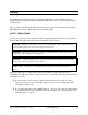
4 Replacement Procedures 4.2 Battery Removing the Battery Pack To remove the battery pack from the battery bay, follow the steps below. 1. Turn the computer upside down. 2. Disengage the battery pack lock (1). 3. Release the battery pack release latch (2). 4. Remove the battery pack from the bay (3). Figure 4-1 Removing the battery pack NOTE: For environmental reasons, do not throw away a spent battery pack. Please return spent battery packs to Toshiba.
4 Replacement Procedures Installing the Battery Pack To install the battery pack in the battery bay, follow the steps below and refer to the figure in the preceding section. WARNING: The battery is a lithium ion battery and can explode if not properly replaced, used, handled or disposed of. Use only batteries recommended by Toshiba as replacements. 1. Slide the battery pack into the battery bay. The battery bay latch will click automatically. 2.
4 Replacement Procedures 4.3 PC Card Removing a PC Card To remove a PC Card, follow the steps below. 1. Push the PC Card’s eject button. The button pops out when you release it. 2. Push the eject button once more to pop the PC Card out slightly. 3. Grasp the PC Card and remove it. 4. Push the eject button back into place, if necessary.
4 Replacement Procedures Installing a PC Card To install a PC Card, follow the steps below and refer to the figures in the preceding section. 1. Make sure the eject button does not stick out. 2. Insert a PC Card and press gently to ensure a firm connection.
4 Replacement Procedures 4.4 HDD NOTE: When handling the HDD, do not press the top surface as shown by the arrow. Hold it by the sides. Figure 4-4 HDD Removing the HDD Module Follow the steps below to remove HDD module: 1. Turn the computer upside down 2. Remove two black M2.5x5 screws to release the HDD door.
4 Replacement Procedures Figure 4-5 Removing the HDD door 3. Pull on the tab to remove the HDD unit. Figure 4-6 Removing the HDD module 4. Remove the HDD from the HDD case. Installing the HDD Module To install the HDD module, follow the steps below and refer to the figures in the preceding section. 1. Insert the HDD module into the HDD case. 2. Secure the HDD door with two black M2.5x5 screws.
4 Replacement Procedures Disassembling the HDD Module To take apart the HDD module, first remove it from the computer as described earlier. 1. Remove four M3x3 screws securing the HDD mounting brackets to the HDD. There are two on each side.
4 Replacement Procedures 4.5 Optical Drive Module Removing the Optical Drive Module To remove the optical drive module, follow the steps below: 1. Turn the computer upside down. 2. Remove one M2.5x5 screw securing the optical drive module into place. 3. Remove one M2.5x5 screw securing the wireless LAN compartment cover, then open it. 4. Insert your finger into the gap directly behind the ODD then press it gently to eject it slightly from the ODD bay. 5.
4 Replacement Procedures 4.6 Optical Drive This computer may be fitted with a: CD-RW/DVD-ROM device DVD+-R/+-RW DVD Super Multi device Disassembling the Optical Drive To disassemble the optical drive, then follow the steps below. 1. Remove one M2.5x5 screw and slide the optical drive module from the bay. (Refer 4.5 Optical Drive Module) 2. Remove two M2x3 screws from the bracket plate. Remove the bracket plate.
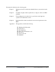
4 Replacement Procedures 4.7 Wireless LAN Removing the Wireless LAN 1. Turn the computer upside down and loosen the embedded M2.5x5 screw securing the wireless LAN compartment cover. Figure 4-10 Removing the wireless LAN cover 2. Lift off the wireless LAN compartment cover. 3. Remove the embedded one M2.5x3.6 screw securing the Mini PCI bracket. Note: If your wireless LAN unit is an ‘A’ type card, then the screw will be a safety screw. 4. Detach the two ends of the wireless LAN antenna. 5.
4 Replacement Procedures Figure 4-11 Removing the wireless LAN unit CAUTION: Do not touch the connectors on the wireless LAN unit or on the computer. Debris on the connectors may cause malfunction. Installing the Wireless LAN To install the wireless LAN unit, follow the steps below and refer to the figures in the preceding section. 1. Turn the computer upside down and loosen the embedded M2.5x5 screw securing the wireless LAN compartment cover. 2. Lift off the wireless LAN compartment cover. 3.
4 Replacement Procedures 4.8 Modem Removing the Modem To remove the installed modem, remove the Wireless LAN compartment cover and then follow the steps below: 1. Remove two black M2.5x3 screws securing the modem module. 2. Carefully lift the unit off its connector 3. Disconnect the modem cable from the modem module. Figure 4-12 Removing the modem module Installing the Modem To install a modem, follow the steps below and refer to the figures in the preceding section. 1.
4 Replacement Procedures 4.9 Expansion Memory Module Removing an Expansion Memory To remove an expansion memory module, make sure the computer is in boot mode then: 1. Be sure the power is off and all cables are disconnected from the computer. 2. Turn the computer upside down and remove the battery pack. Loosen the embedded M2.5x5 screw securing the Wireless LAN compartment cover. Figure 4-13 Removing the memory module cover 3.
4 Replacement Procedures 6. Seat the cover and secure its screw. 7. Replace the battery pack. Figure 4-14 Removing a memory module CAUTION: Do not touch the connectors on the expansion memory or on the computer. Debris on the connectors may cause memory access problems.
4 Replacement Procedures Installing an Expansion Memory Module CAUTION: Do not touch the connectors on the expansion memory or on the computer. Debris on the connectors may cause memory access problems. Follow these steps to install a memory module: 1. Set the computer to boot mode and turn off the power. 2. Remove all cables connected to the computer. 3. Turn the computer upside down and remove the battery. Loosen the embedded M2.5x5 screw securing the memory module socket cover.
4 Replacement Procedures 6. Push the module down so it lies flat. Latches on either side will click into place to secure the module.
4 Replacement Procedures 4.10 Keyboard Removing the Keyboard Follow the steps below to remove the keyboard: 1. Open the display panel. 2. Remove the strip cover by forcing one end of the strip cover up. Figure 4-17 Removing the strip cover 3. Remove two black M2.5×3 screws securing the keyboard.
4 Replacement Procedures Figure 4-18 Removing the keyboard 4. After removing the screws, flip the keyboard latch with either a screwdriver or a fingernail. 5. Lift the keyboard out of its bay, revealing the keyboard cable. 6. Disconnect the keyboard cable and remove the keyboard from the computer entirely.
4 Replacement Procedures Figure 4-19 Disconnecting the keyboard cable Installing the Keyboard To install the keyboard, follow the steps below and refer to the figures in the preceding section. 1. Connect the keyboard cable to the system board. 2. Set the keyboard in place and secure it with two black M2.5x3 screws. 3. Engage the flip latch with either a screwdriver or a fingernail. 4. Set the strip cover and press down to secure the strip cover latches engage.
4 Replacement Procedures 4.11 Display Assembly Removing the Display Assembly To remove the display assembly, first remove the keyboard and wireless LAN, then follow the steps below: 1. Remove two black M2.5x8 screws from the back side of the computer. Figure 4-20 Removing the display assembly screws 2. Remove the strip cover. 3. Disconnect the wireless cable (1) from system. 4. Disconnect the LCD cable (2) from system. 5. Remove two M2.5x8 black screws securing LCD hinge.
4 Replacement Procedures M2.5X8 M2.5X8 1 2 Figure 4-21 6. Removing the wireless and LCD cables Lift the display assembly from the computer’s chassis. Installing the Display Assembly To install the display assembly, follow the steps below and refer to the figures in the preceding section. 1. Seat the display assembly taking care not to crush to the LCD cable or wireless cable. 2. Secure two M2.5x8 black screws to LCD hinge. 3. Connect the LCD cable to the top chassis. 4.
4 Replacement Procedures 4.12 Top Cover Removing the Top Cover To remove the top covers, first remove the battery pack, display assembly, optical drive module, HDD, memory module and wireless LAN as described in the preceding sections, then follow the steps below: 1. Remove seven black M2.5x8 and eight black M2.5x5 securing from bottom.
4 Replacement Procedures 2. Remove one black M2.5x5 and three black M2.5x14 screws securing the top half of the cover: Figure 4-23 Removing the top cover 3. Detach the Touch Pad FFC cable.
4 Replacement Procedures 4. Detach the speaker cable. Figure 4-25 Removing Speaker cables 5. Detach the Direct Play Button Board FFC cable. 6. Remove the top cover. Installing the Top Cover To install the top cover, follow the steps below and refer to the figures in the preceding section. 1. Seat the top cover and secure the Touch Pad FFC cable. 2. Connect the Direct Play Button Board FFC cable. 3. Connect the speaker cable. 4. Secure the top cover with one black M2.5x5 and three black M2.
4 Replacement Procedures 4.13 Direct Play Button Board Removing the Direct Play Button Board To remove the Direct Play Button board, first remove the Top Cover then follow the steps below: 1. Remove two M2.5x 3 screws and FFC from top cover. M2.5X3 FFC Figure 4-26 Removing the Direct Play Button board Installing the Direct Play Button Board To install the Direct Play Button board, follow the steps below and refer to the figures in the preceding section. 1. Secure two M2.
Appendices [CONFIDENTIAL]
Appendices App-ii [CONFIDENTIAL] Satellite A80/A85 Series Maintenance Manual
Appendix Contents Appendix A Handling the LCD Module............................................................................... A-1 Appendix B Board Layout..................................................................................................... B-1 B.1 System Board (FRDSY*) Bottom View......................................................................... B-1 B.2 System Board (FRDSY*) Top View ..............................................................................
Appendices Figures Figure B-1 System board (FRDSY*) layout (Bottom).......................................................... B-1 Figure B.2 System board (FRDSY*) layout (Top) ............................................................... B-2 Figure E-1 US keyboard ........................................................................................................ E-1 Figure E-2 UK keyboard .......................................................................................................
Tables Table B-1 System board ICs (top and bottom) .................................................................... B-3 Table B-2 System board connectors (top and bottom) ........................................................ B-4 Table C-1 SODIMM I/F pin assignments (200-PIN) .......................................................... C-1 Table C-2 LCD I/F pin assignments (22-pin) ......................................................................
Appendix A Appendix A Handling the LCD Module Precautions for handling the LCD module The LCD module can be easily damaged during assembly or disassembly. Therefore, please observe the following precautions when handling it: 1. When installing the LCD module in the LCD cover, be sure to seat it so that it is properly aligned and maximum visibility of the display is maintained. 2.
3. If the panel’s surface gets dirty, wipe it with cotton or a soft cloth. If it is still dirty, try breathing on the surface to create a light condensate and wipe it again. If the surface is very dirty, we recommend a CRT cleaning agent. Apply the agent to a cloth and then wipe the panel’s surface. Do not apply cleanser directly to the panel. CRT Cleaner 4. If water or other liquid is left on the panel’s surface for a long period, it can change the screen’s tint or stain it.
5. Glass is used in the panel, so be careful not to drop it or let it strike a hard object, which could cause breakage or cracks. 6. CMOS-LSI circuits are used in the module, so guard against damage from electrostatic discharge. Be sure to wear a wrist or ankle ground when handling the module.
7. Do not expose the module to direct sunlight or strong ultraviolet rays for long periods. 8. Do not store the module at temperatures below specifications. Cold can cause the liquid crystals to freeze, lose their elasticity or otherwise suffer damage. 9. Do not disassemble the LCD module. Disassembly can cause malfunctions.
10. If you transport the module, do not use packing material that contains epoxy resin (amine) or silicon glue (alcohol or oxime). These materials can release gas that can damage the panel’s polarization.
A-6 [CONFIDENTIAL] Satellite A80/A85 Series Maintenance Manual
Appendix B Appendix B Board Layout B.
B.
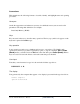
Table B-1 System board ICs (top and bottom) Mark Number (A) U6 ATI –RL300MB (B) U9 SB200 (C) U15 ENE 910 (D) U13 REALTEK 8100CL (E) U28 RealTEK ALC250VD (F) U5 Transformer-NS0013 (G) U25 TI PCI1410 (H) U32 ICS951402AGT (I) U16 BIOS ROM Satellite A80/A85 Series Maintenance Manual Name [CONFIDENTIAL] B-3
Table B-2 System board connectors (top and bottom) Number B-4 Name JP1 CRT conn. JP2 LAN/B conn. JP4 Power/B conn.
C. Appendix C Pin Assignments System Board C.1 JP9,JP19 Table C-1 SODIMM I/F pin assignments (200-PIN) (1/4) Pin No. Signal name I/O Pin No. Signal Name I/O 1 VREF O 2 VREF O 3 VSS - 4 VSS - 5 DQ0 I/O 6 DQ4 I/O 7 DQ1 I/O 8 DQ5 I/O 9 25VDD O 10 2.5VDD O 11 DQS0 I/O 12 DM0 O 13 DQ2 I/O 14 DQ6 I/O 15 VSS - 16 VSS - 17 DQ3 I/O 18 DQ7 I/O 19 DQ8 I/O 20 DQ12 I/O 21 2.5VDD O 22 2.
Table C-1 SODIMM I/F pin assignments (200-PIN) (2/4) Pin No. C-2 Signal name I/O Pin No. Signal Name - 52 VSS I/O 51 VSS 53 DQ19 I/O 54 DQ23 I/O 55 DQ24 I/O 56 DQ28 I/O 57 2.5VDD O 58 2.5VDD O 59 DQ25 I/O 60 DQ29 I/O 61 DQS3 I/O 62 DM3 O 63 VSS - 64 VSS - 65 DQ26 I/O 66 DQ30 I/O 67 DQ27 I/O 68 DQ31 I/O 69 2.5VDD O 70 2.
Table C-1 SODIMM I/F pin assignments (200-PIN) (3/4) Pin No. Signal name I/O Pin No. Signal Name I/O 115 A10/AP O 116 BA1 O 117 BA0 O 118 RAS# O 119 WE# O 120 CAS# O 121 SO# O 122 S1# - 123 DU - 124 DU - 125 VSS - 126 VSS - 127 DQ32 I/O 128 DQ36 I/O 129 DQ33 I/O 130 DQ37 I/O 131 2.5VDD O 132 2.
Table C-1 SODIMM I/F pin assignments (200-PIN) (4/4) Pin No. C-4 Signal name I/O Pin No. Signal Name I/O 181 DQ57 I/O 182 DQ61 I/O 183 DQS7 I/O 184 DM7 O 185 VSS - 186 VSS - 187 DQ58 I/O 188 DQ62 I/O 189 DQ59 I/O 190 DQ63 I/O 191 2.5VDD O 192 2.5VDD O 193 SDA I/O 194 SA0 O 195 SCL O 196 SA1 O 197 3.
C.2 JP1 Table C-2 RGB I/F pin assignments (15-pin) Pin No. Signal name I/O Pin No.
C.3 JP15 Table C-3 HDD I/F pin assignments (44-pin) Pin No. C-6 Signal name I/O Pin No.
C.4 JP10 Table C-4 ODD I/F pin assignments (50-pin) Pin No. Signal name I/O Pin No.
C.5 JP15 Table C-5 PC Card I/F pin assignments (88-pin) (1/2) Pin No. C-8 Signal name I/O Pin No.
Table C-5 PC Card I/F pin assignments (88-pin) (2/2) Pin No. Signal name I/O Pin No.
C.6 JP20 Table C-6 Mini PCI I/F pin assignments (124-pin) (1/2) Pin No. C-10 Signal name I/O Pin No. Signal Name I/O 1 NC - 2 NC - 3 NC - 4 NC - 5 NC - 6 NC - 7 NC - 8 NC - 9 NC - 10 NC - 11 NC - 12 NC - 13 SWITCH O 14 NC - 15 NC - 16 NC - 17 PIRQH# I 18 +5VS_MINIPCI - 19 +3.3V O 20 PIRQG# I 21 NC - 22 NC - 23 GND - 24 +3.3V O 25 PCICLK O 26 PCIRST# O 27 GND - 28 +3.3V O 29 REQ1# I 30 GNT1# O 31 +3.
Table C-6 Mini PCI I/F pin assignments (124-pin)(2/2) Pin No. Signal name I/O Pin No. Signal Name I/O 61 IRDY# I/O 62 GND 63 +3.3V O 64 FRAME# I/O 65 PM_CLKRUN# I/O 66 TRDY# I/O 67 PCI_SERR# I/O 68 STOP# I/O 69 GND - 70 +3.
C.7 JP6 Pin No. C-12 Signal name Function 1 B+ Power 2 DAC_BRIG Inverter Control signal 3 B+ Power 4 INVT_PWM Inverter Control signal 5 NC Non-Connection 6 DISPOFF# Inverter Control signal 7 +3VS DDC 3.3V POWER SUPPLY : +3.
C.8 34 TXACLK+_NB Panel Clock Signals 35 NC Non-Connection 36 NC Non-Connection 37 NC Non-Connection 38 NC Non-Connection 39 NC No EDID Panel Detect 40 VSS GND JP8 Table C-8 JP8 Fan I/F pin assignments (3-pin) Pin No. C.9 Signal name I/O Pin No. Signal Name I/O 2 FAN-SPEED1 O 1 FAN1 I 3 GND - PJP1 Table C-9 AC Adaptor Connector pin assignments (3-pin) Pin No. Signal name I/O Pin No.
C.10 JP18 Table C-10 Microphone I/F pin assignments (6-pin) Pin No. C.11 Signal name I/O Pin No. Signal Name I/O 1 ANGND - 2 MIC I 3 BIAS I 4 NC - 5 NC - 6 ANGND - JP17 Table C-11 Headphone Connector pin assignments (6-pin) Pin No. C-14 Signal name I/O Pin No.
Appendix D Appendix D Keyboard Scan/Character Codes Table D-1 Scan codes (set 1 and set 2) (1/4) Cap No.
Table D-1 Scan codes (set 1 and set 2) (2/4) D-2 Cap No.
Table D-1 Scan codes (set 1 and set 2) (3/4) Cap No.
Table D-1 Scan codes (set 1 and set 2) (4/4) Cap No. Keytop Code set 1 122 F11 57 D7 78 F0 78 *3 123 F12 58 D8 07 F0 07 *3 124 PrintSc *6 *6 *6 *6 *6 126 Pause *7 *7 *7 *7 *7 X Fn — — — — *4 X Win E0 5B E0 DB E0 1F E0 F0 1F x App E0 5D E0 DD E0 2F E0 F0 2F Make Code set 2 Break Make Note Break Notes: 1. 2. 3. 4. 5. 6. 7. D-4 * * * * * * * Scan codes differ by mode. Scan codes differ by overlay function.
Table D-2 Scan codes with left Shift key Cap Key Code set 1 No.
Table D-3 Scan codes in Numlock mode Cap Key Code set 1 No.
Table D-5 Scan codes in overlay mode Cap No. Code set 1 Keytop Code set 2 Make Break Make Break 09 8 (8) 48 C8 75 F0 75 10 9 (9) 49 C9 7D F0 7D 11 0 (*) 37 B7 7C F0 7C 23 U (4) 4B CB 6B F0 6B 24 I (5) 4C CC 73 F0 73 25 O (6) 4D CD 74 F0 74 26 P (–) 4A CA 7B F0 7B 37 J (1) 4F CF 69 F0 69 38 K (2) 50 D0 72 F0 72 39 L (3) 51 D1 7A F0 7A 40 ; (+) 4E CE 79 F0 79 52 M (0) 52 D2 70 F0 70 54 . (.
Table D-7 No.126 key scan code Key top Pause Shift Code set 1 Code set 2 Make Make Common E1 1D 45 E1 Ctrl E0 46 E0 C6 9D C5 E1 14 77 E1 F0 E0 7E E0 F0 7E 14 F0 77 *: This key generates only make codes.
Appendix E Appendix E E.1 Key Layout United States (US) Keyboard Figure E-1 US keyboard E.
Figure E-2 UK keyboard E-2 [CONFIDENTIAL] Satellite A80/A85 Series Maintenance Manual
E.3 Spanish (SP) Keyboard Figure E-3 SP keyboard E.
E.5 Korean (KO) Keyboard Figure E-5 KO keyboard E.
E.7 Portuguese (PO) Keyboard Figure E-7 PO keyboard E.
E.9 Germanic (GR) Keyboard Figure E-9 GR keyboard E.
Figure E-10 FR keyboard E.11 Chinese (CH) Keyboard Figure E-11 CH keyboard E.
E.13 Italian (IT) Keyboard Figure E-13 IT keyboard E.
E.15 Arabic (AR-E) Keyboard Figure E-15 AR-E keyboard E.
E.17 Estonian (EST) Keyboard Figure E-17 EST keyboard E.
E.19 Hebrew (HB) Keyboard Figure E-19 HB keyboard E.
E.21 Norwegian (NW) Keyboard Figure E-21 NW keyboard E.
E.23 Lithuanian (LIT) Keyboard Figure E-23 LIT keyboard E.
E.25 Turkish (TR) Keyboard Figure E-25 TR keyboard E.
E.27 Danish (DM) Keyboard Figure E-27 DM keyboard E.
E.
Appendix G Appendix F Series Screw Torque List Table F-1 Series Screw Torque List SCREW P/N SCREW SPEC Q'ty LOCATION SCREW TORQUE MMCK25050Z0 M2.5*5 4 LCD BRACKET ASSY (R/L) TO COVER SUB ASSY 2.5~3.0kg MMCK20030Z0 M2.0*3 8 LCD BRK TO LCD PANEL (15") 2.0~2.5kg MMCK20030Z0 M2.0*3 1 INVERTER TO COVER SUB ASSY 2.0~2.5kg MMCK20030Z0 M2.0*3 1 LCD CABLE TO COVER 2.0~2.5kg MM000000100 M2.0*4 4 PCMCIA TO MB 1.5~2.0kg MM000000100 M2.0*4 2 BATT CONN TO MB 1.5~2.
SCREW P/N SCREW SPEC Q'ty LOCATION SCREW TORQUE MACK25080Z0 M2.5*8 1 LOG LOW TO HINGE SADDLE R TO LOG UP 2.5~3.0kg MACK25080Z0 M2.5*8 1 LL TO LL SHIELD TO MB TO LU 2.5~3.0kg MACK25080Z0 M2.5*8 1 LL TO LL SHIELD MB STANDOFF TO HINGE SADDLE TO LU 2.5~3.0kg MACK25080Z0 M2.5*8 1 LL TO LL SHIELD TO HINGE SADDLE TO LU 2.5~3.0kg MACK25080Z0 M2.5*8 1 LL TO LL SHIELD HINGE SADDLE TO LU 2.5~3.0kg MACK25080Z0 M2.5*8 2 LL TO LL HDD SHIELD TO VR_USB_BOARD TO LU 2.5~3.
F-3 MMCK25030Z0 M2.5*3 2 KB TO TOP SHIELD BATT TO LU 2.5~3.0kg MMCK25030Z0 M2.5*3 1 RJ11/45 PCB TO LL SHIELD TO LL 2.5~3.0kg MMCK25030Z0 M2.5*3 2 MDC MODEN TO MDC MODEN STANDOFF 2.5~3.0kg MMCK25030Z0 M2.5*3 1 LCD WIRE TO UP 2.5~3.0kg MMCK20030Z0 M2.0*3 2 BLUETOOTH BOARD TO BLUETOOTH STANDOFF 2.0~2.5kg MMCK20030Z0 M2.0*3 2 FIX BAY BRACKET WITH DRIVER 2.0~2.5kg MM000000200 M2.5*3.6 (SPECIAL SCREW) 1 MINI PCI BRACKET TO LOG LOW 2.5~3.0kg MM000000300 M2.5*3.
Appendix G Appendix G Reliability The following table shows MTBF (Mean Time Between Failures) for each component.
G-2 [CONFIDENTIAL] Satellite A80/A85 Series Maintenance Manual