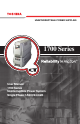
UNINTERRUPTIBLE POWER SUPPLIES 1700 Series User Manual 1700 Series Uninterruptible Power System Single Phase 1.5/2.0/2.
IMPORTANT NOTICE The instructions contained in this manual are not intended to cover all of the details or variations in equipment, nor to provide for every possible contingency to be met in connection with installation, operation, or maintenance. Should further information be desired or should particular problems arise which are not covered sufficiently for the purchaser's purposes, the matter should be referred to the local Toshiba sales office.
TABLE OF CONTENTS SECTION PAGE Disclaimer ................................................................................................ 3 Table of Contents.................................................................................... 4 General Safety Instructions ................................................................... 5 Important Safety Instructions .............................................................6-7 Inspection/Installation ..................................................
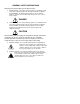
GENERAL SAFETY INSTRUCTIONS Warnings in this manual appear in two different ways: 1) Danger warnings - The danger warning symbol is an exclamation mark enclosed in a triangle that precedes the large bold letters spelling the word "DANGER".
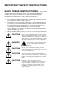
IMPORTANT SAFETY INSTRUCTIONS SAVE THESE INSTRUCTIONS. This manual contains important instructions for the 1.5 and 2.4kVA 1700 Series Toshiba UPS. These instructions should be followed during the installation and maintenance of the UPS and its batteries. ¾ ¾ ¾ The maximum ambient temperature in which this UPS unit should be operated or stored is 104 °F (40 °C). The batteries for the Toshiba 1700 Series 1.5 and 2.4kVA UPS are housed in a self-contained battery module.
INSTRUCTIONS IMPORTANTES CONCERNANT LA SÉCURITÉ CONSERVER CES INSTRUCTIONS. Cette notice contient des instructions importantes concernant la sécurit. ATTENTION Une batterie peut présenter un risque de choc électrique, de brûlure par transfert d’énergie. ATTENTION Pour le remplacement, utiliser le même nombre de batteries du modèle suivant. ATTENTION L’élimination des batteries est réglementée. Consulter les codes locaux à cet effet.
Inspection/Installation Inspection of the New UPS Equipment Upon receipt of the UPS, a careful inspection for shipping damage should be made. After Unpacking: 1) Check the unit for loose, broken, bent or otherwise damaged parts. If damage has occurred during shipment, keep all original packing materials for return to shipping agent. Warranty will not apply to units damaged during shipment.
2) The input power source voltage and frequency must be within the allowable range as specified in appendix A. Voltages and frequencies outside of the permissible tolerance range may cause internal protection devices to activate. 3) The UPS should not be used with a load whose rated input is greater than the rated UPS output.
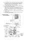
Battery Module Figure 2 Battery Module Layout UPS Connections Standard Module Connections The illustration on the following page shows the proper assembly of the two modules that make up the standard unit. If additional battery modules are being installed with the standard unit see page 20. For all other option modules see page 21. Note: No more than three modules should be stacked on top of each other for any configuration.
Standard Module Connections (cont’d) If two modules are to be stacked on top of each other, they should be interlocked to reduce the chances of the top module being knocked over. Modules do not have to be stacked for the system to operate. The following steps will guide the user through the process of assembling and connecting the modules.
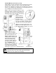
Operating the UPS Display Panel Layout Function Control Button Startup on Battery Button ON LINE (green lamp) Lights green when the UPS’s inverter is supplying power to the load. AC INPUT (green lamp) Lights green when normal AC input power is being supplied to the UPS unit. WARNING/FAULT (red lamp) Lights red when the UPS unit is experiencing an abnormal condition. BATTERY (red lamp) Lights red to indicate that a condition exists that is affecting the batteries.
Starting on DC Power If no AC power source is available, or if the AC input power is outside of the allowable range for voltage or frequency, the UPS can be started from battery power. The length of UPS operation time on battery power depends on the number of attached battery modules and the amount of load the UPS is supporting. To start the UPS from battery power follow these steps: Step 1: Make sure the RUN/STOP switch is in the STOP position.
Bypass Battery Backup Normal Operation Mode Display State *see note 1. AC Input ........... On 20% to 100%* .. On *see note 2. On Line............. On Battery.............. On Backup ............. On 20% to 100%* .. On *see note 1. On Line............. On AC Input ........... On 20% to 100%* .. On LED State UPS Display Status and Operating Condition Alarm is off. Alarm will sound for 1 second at 10 second intervals. Alarm is off. Alarm State Battery backup is not available.
Display State *see note 1. On Line............. On AC Input ........... On Battery.............. On 20% to 100%* .. On LED State Alarm will sound for 1 second at 10 second intervals. Alarm State Parallel operation occurs when input power is present, but inadequate to fully power the connected load. The batteries are used to supplement the AC input power. The UPS will return to normal operation when full input power returns.
Battery Backup Time The exact amount of backup time provided will vary depending on the UPS model being used, number of batteries, condition of the batteries and other factors. However, the chart below gives the times that can be expected from the standard units with batteries in good condition. For greater backup time, an additional battery module may be added to the standard unit. Only one additional battery module may be added to the standard unit.
Fan Speed The 1700 Series UPS has variable speed fans. The fan speed will vary depending on a number of factors. As the load placed on the UPS increases the fan speed will increase. The temperature of the environment the UPS is operating in can also cause the fan speed to increase.
unit is in programming mode. (If at anytime while the UPS is in the programming mode there is one minute of inactivity the UPS will automatically exit the programming mode and return to bypass operation.) What follows is a step by step guide to navigating in the programming mode, followed by a detailed description of each option. A. Load Shed.
Function Control button successive times will increase the load shed level in 20% increments. A.2 Once the option is set to the desired level, press and hold the Function Control button. This will save the new load shed level setting. The UPS will indicate that the value has been stored by blinking the LEDs. After blinking the LED for a short time the UPS will exit the programming mode and return to bypass operation.
Fixed Frequency Mode The 1700 Series UPS has the option of operating in a fixed frequency mode. Normally the UPS operates in the frequency autodetect mode. If a specific output frequency is required (i.e. 50Hz or 60Hz) the UPS can be set at the factory to supply the desired frequency regardless of the input frequency (input frequency must be within allowable limits, see Specifications on page 31). For a unit already in use the output frequency can be set through software.
Other Option Modules There are a number of other optional modules that can be ordered for the 1700 Series UPS system. Table 3 shows some of the available option modules. For information about options not listed here contact Toshiba’s UPS Marketing Department at (800) 2311412 or by e-mail at toshibaups@tic.toshiba.com. Table 3 Option Modules Input Output Part No.
Communication Interface Dry Contacts The remote contacts interface is a standard feature. It is provided through solid state relays with contacts through a DB9 male connector located on the back of the UPS (refer to the Communication Option User Manual for a more detailed description of this option). The following chart shows the signals and the connector pinout.
Pin Signal Name Description 1 - 2 RXD Receive data 3 TXD Transmit data 4 DTR Data terminal ready 5 GND Signal ground 6 DSR Data set ready 7 RTS Request to send 8 CTS Clear to send 9 - In the UPS (*) (**) These pins are tied together internal to the UPS. Signals DTR, DSR, RTS, and CTS are not used.
Option Card Slot The option card slot is a standard feature. An optional network adapter card slides into the slot which is located on the back of the electronics module (figure 1, page 9). This optional interface allows the UPS to be monitored across the network or from any point on the Internet (refer to the Communication Option User Manual for a more detailed explanation of this option).
Warning/Fault... Flash 80% .................. Flash Warning/Fault... Flash 100% ................ Flash Current Limit (Over Current) Ambient Over Heat LED State Warning/Fault... Flash Backup ............. Flash Display State Low Battery Warning Warnings Alarm will sound for 1-second at 15second intervals. Alarm will sound for 1/2second at 1-second intervals. Alarm will sound for 1-second at 5second intervals. Alarm State The temperature of the UPS operating environment is too high.
This warning will occur if the input voltage exceeds the maximum allowable voltage. If the unit was online when the warning occurred it will transfer to battery backup (see note 2). If the unit was in bypass the output will be turned off. The unit will return to normal operation if input power returns to within specified limits. Alarm will sound for 2, 1/2second beeps at 10second intervals. Warning/Fault... Flash 40% ..................
Display State The connected load exceeds the UPS power rating. Reduce the load attached to the UPS. The unit will automatically return to normal operation. Alarm will sound for 1-second at 15second intervals. Warning/Fault... Flash 150% ................ Flash = LED lit continuously The input frequency is outside specified limits. If the unit was online when the warning occurred it will transfer to battery backup. After the backup the output will shutdown.
Warning/Fault... On Backup ............. On Warning/Fault... On 20% .................. On Battery Shutdown DC Bus Over Current LED Warning/Fault... On Battery.............. On Display State Replace Battery Fault Faults Battery pack is not connected or needs replacement as soon as possible. After replacing the batteries the battery timer must be reset (see “The Function Control Button”, page 17).
Warning/Fault... On 60% .................. On Warning/Fault... On 80% .................. On DC Bus Voltage Imbalance Output Under Voltage LED State Warning/Fault... On 40% .................. On Display State DC Bus Over Voltage Fault Faults Alarm will sound for 1/2second, at 1/2second intervals. Alarm State These faults indicate an internal problem with the UPS. Contact your Toshiba UPS service representative at 1877-867-8773 (outside the U.S. call 713-466-0277).
= Flashing LED = LED lit continuously Warning/Fault... On 150% ................ On System Over Heat LED State Warning/Fault... On 100% ................ On Display State Output Over Voltage Fault Faults Alarm will sound for 1/2second, at 1/2second intervals. Alarm State These faults indicate an internal problem with the UPS. Contact your Toshiba UPS service representative at 1877-867-8773 (outside the U.S. call 713-466-0277).
Storage of UPS Equipment. General Guidelines If the UPS equipment is to be stored; the following guidelines should be used. Avoid: 1) Storage in sites subject to extreme changes in temperature or high humidity. 2) Storage in sites subject to exposure of high levels of dust or metal particles 3) Storage on inclined floor surfaces or in sites subject to excessive vibration. Before Storing: 1) Allow UPS to be operated for 4 hrs to ensure that the batteries are fully charged.
Preventive and Scheduled Maintenance/Parts Replacement Preventive Maintenance Toshiba's 1700 Series of UPS systems have been designed to provide years of trouble-free operation requiring a minimum of preventive maintenance. The best preventive measure is to keep the area around the unit, particularly the air inlet vents, clean and free of moisture and dust accumulations.
Appendix A: Specifications Model Number UF1A1A015C6(T) Capacity 1500VA (1.05KW) 2000VA (1.40KW) 2400VA (1.68KW) Input Input voltage 1 Input capacity Bypass Output Battery Input voltage 2 30 to 70 Hz 1500VA 2000VA Single phase 120VAC, ±10% Single phase 120VAC Overload rating See appendix C Output voltage Output voltage regulation Output frequency Rated load power factor Rated output current (rms) Inverter overload capacity Crest factor Single phase 120VAC (fully charged, 0.
Appendix B: Fan Speed Control The fans in the 1700 Series will operate at any of four different speeds depending on the environment and system conditions. In the first stage the fans are off. As the load and or the temperature increase the fans will subsequently go to low, medium or high speed as required. The temperature reference given on the graph above refers to the temperature inside the UPS. There will typically be a 5°C difference between the internal and external temperature.
Appendix C: System Overload Rating The 1700 Series UPS is capable of supporting short duration overloads. When operating in the On Line mode output overloading of 125% of the rated output current can be supported for 1 minute, and 150% for 30 seconds. If the overload continues the unit will switch to bypass mode. When in bypass mode the 1700 Series overload capacity is limited by the input breaker. The following graph shows the response of the breaker depending on the applied load.
Appendix D: Parallel Operation The 1700 Series UPS offers a standard feature that allows the unit to operate with very low input voltage without de-rating the output power. If the input voltage drops below a certain point the unit will switch to parallel mode. Parallel mode means that the unit is using the available input voltage and supplementing with battery power. Because battery power is being used, the time the unit can operate in parallel mode is limited.
Appendix E: Bypass Undervoltage / Overvoltage When the 1700 Series UPS is in bypass mode the undervoltage and overvoltage limits are restricted to +/-10% of the rated input voltage. If the input voltage is outside of this voltage window the UPS output will be turned off. There is a 5% hysteresis associated with both the upper and lower limits. This means that once output has been turned off the input voltage will have to be within ±5% of the rated input voltage before the startup sequence will reinitialize.
Appendix F: Unit Configuration Options The following chart shows the configuration options for each base model UPS.
\Appendix G: Weights and Dimensions Module Model No.
TOSHIBA INTERNATIONAL CORPORATION LIMITED WARRANTY POLICY (48 contiguous U.S. States, Canada, Mexico) (UNINTERRUPTIBLE POWER SUPPLIES-UPS) TOSHIBA INTERNATIONAL CORPORATION (“TIC”) warrants that the 1700 Series Uninterruptible Power Supplies (“UPS”) and Uninterruptible Power Supply Battery (“BATTERY”) (external battery cabinet) sold by TIC to the end user (“User”) shall be free of defects in material and workmanship.
PROCEDURE User must contact TIC via e-mail upsservice@tic.toshiba.com, or phone 1-877-867-8773 (outside the U.S. call 713-466-0277), no later than 90 days after User’s discovery of occurrence or defect in UPS, UPS part, and/or BATTERY but in no event after the expiration of the respective warranty period. Subject to the limitations of this policy and product type, TIC service or TIC service representative shall repair/replace the UPS/part warranted hereunder, without charge for material, labor.
Notes:
Notes:
TOSHIBA TOSHIBA INTERNATIONAL CORPORATION INDUSTRIAL DIVISION 13131 West Little York Rd.