UM-V200-E001 Programmable Logic Controllers USER’S MANUAL Setup & Operation CONTENTS V200 Series PLC Toshiba International Corporation
Thank you for purchasing the V200 Series PLC (Programmable Logic Controller) product from Toshiba International Corp. V200 Series products are versatile PLCs which are configured with Microsoft Windows based software. Manual’s Purpose and Scope This manual provides information on how to safely install, operate, and maintain your TIC V200 Series PLC. This manual includes a section of general safety instructions that describes the warning labels and symbols that are used throughout the manual.
Important Notice The instructions contained in this manual are not intended to cover all details or variations in equipment types, nor may it provide for every possible contingency concerning the installation, operation, or maintenance of this equipment. Should additional information be required contact your Toshiba representative. The contents of this manual shall not become a part of or modify any prior or existing agreement, commitment, or relationship.
Manual Revisions Please have the following information available when contacting Toshiba International Corp. about this manual. Name: V200 User’s Manual Document: UM-V200-E001 Revision: Rev No.
Table of Contents GENERAL SAFETY INSTRUCTIONS & INFORMATION ....................................................................... 1 0.1 Warning Labels Within Manual ........................................................................................................ 2 0.2 Equipment Warning Labels. ............................................................................................................. 4 0.3 Preparation ................................................................................
2.6 Installation Instructions .................................................................................................................... 57 2.7 Wiring Diagram ................................................................................................................................. 61 2.8 Communication Ports....................................................................................................................... 61 2.9 Communication Cables .......................................
OPERATING SYSTEMS OVERVIEW ...................................................................................................... 96 6.1 Operating System Overview ........................................................................................................... 97 6.2 Mode Selection................................................................................................................................. 97 PROGRAMMING INFORMATION ...............................................................
MAINTENANCE AND CHECKS ............................................................................................................. 127 9.1 Precautions During Operation ..................................................................................................... 128 9.2 Daily Checks ................................................................................................................................... 129 9.3 Periodic Checks ...............................................................
GENERAL SAFETY INSTRUCTIONS & INFORMATION • Warning Labels Within Manual • Equipment Warning Labels • Preparation • Installation Precautions • Connection, Protection & Setup • System Integration Precautions • 3rd Party Safety Certifications Page 1
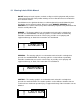
0.1 Warning Labels Within Manual DO NOT attempt to install, operate, maintain, or dispose of this equipment until you have read and understood all of the product warnings and user directions that are contained in this instruction manual. Listed below are the signal words that are used throughout this manual followed by their descriptions and associated symbols.
To identify special hazards, other symbols may appear in conjunction with the DANGER, WARNING, and CAUTION symbols. These warnings describe areas that require special care and/or strict adherence to the procedures to prevent serious injury and possible death. Electrical Hazard — The electrical hazard symbol is a lightning bolt enclosed in a triangle.
0.2 Equipment Warning Labels. DO NOT attempt to install, operate, maintain, or dispose of this equipment until you have read and understood all of the product warnings and user directions that are contained in this instruction manual. Shown below are examples of warning labels that may be found attached to the equipment. DO NOT remove or cover any of the labels. If the labels are damaged or if additional labels are required, contact your Toshiba representative for additional labels.
0.3 Preparation Qualified Person A Qualified Person is one that has the skills and knowledge relating to the construction, installation, operation, and maintenance of the electrical equipment and has received safety training on the hazards involved (Refer to the latest edition of NFPA 70E for additional safety requirements). Qualified Personnel shall: • Have carefully read the entire operation manual.
Handling and Storage • Use proper lifting techniques when moving the V200; including properly sizing up the load, and getting assistance if required. • Store in a well-ventilated covered location and preferably in the original carton if the equipment will not be used upon receipt. • Store in a cool, clean, and dry location. Avoid storage locations with extreme temperatures, rapid temperature changes, high humidity, moisture, dust, corrosive gases, or metal particles.
• As a minimum, the installation of the equipment should conform to the NEC Article 110 Requirements For Electrical Installations, OSHA, as well as any other applicable national, regional, or industry codes and standards. • Installation practices should conform to the latest revision of NFPA 70E Electrical Safety Requirements for Employee Workplaces. Conductor Routing and Grounding • Use separate metal conduits for routing the input power, and control circuits.
0.5 Connection, Protection & Setup Personnel Protection • Installation, operation, and maintenance shall be performed by Qualified Personnel Only. • A thorough understanding of the V200 will be required before the installation, operation, or maintenance of the V200. • Rotating machinery and live conductors can be hazardous and shall not come into contact with humans. Personnel should be protected from all rotating machinery and electrical hazards at all times.
The failure of external or ancillary components may cause intermittent system operation, i.e., the system may start a motor without warning or may not stop on command. • There may be thermal or physical properties, or ancillary devices integrated into the overall system that may allow the V200 to start a motor without warning. Signs at the equipment installation must be posted to this effect.
0.6 System Integration Precautions The following precautions are provided as general guidelines for using an V200 in an industrial or process control system. • The Toshiba PLC is a general-purpose product. It is a system component and is used in conjunction with other items of industrial equipment such as PLCs, Loop Controllers, Adjustable Speed Drives, etc.
0.7 3rd Party Safety Certifications. CE Marking The V200 Series Programmable Controllers conform to the directive and standards of ISO/IEC Guide 22 and EN 45014. UL Certification The UL Mark on a product means that UL has tested and evaluated representative samples of that product and determined that they meet UL requirements. The basic standards used to investigate this category are UL 508, the Standard of Safety for Industrial Control Equipment and UL Standard for Safety for Programmable Controllers.
INTRODUCTION ♦ Purpose of this Manual V200 Basics Programming Computer ♦ V200 Features ♦ V200 Overview What is V200 Series Controller How V200 Works ♦ V200 Series Specifications Page 12
1.1 Purpose of this Manual Thank you for purchasing V200 Series Products from TIC Houston. V200 Series Products are versatile highperformance programmable controllers with Microsoft® Windows based configuration Software. This Manual explains the operation of the V200 Series and how to implement available features using the OIL-DS Software. This manual will help you to install, configure and operate your V200 product. 1.1.
1.1.2 Programming Computer The following basic PC hardware configuration is needed to configure and operate your OIL-DS Configuration Software. Minimal PC configuration for Windows2000 / XP: DEVICE RECOMMENDED Processor 800MHz Pentium processor OR euivalent processor Operating System Microsoft Windows 2000 with SP4 Microsoft Windows XP Professional / Home Edition with SP2 RAM 256MB Hard Disk Space 800MB (including 200MB for the .
1.
1.3 V200 Overview 1.3.1 What is a V200 Series Controller V200 Series units are compact, easy-handling block style programmable controller. It also has modular expandability. Configuration of V200 unit: Each V200 CPU has to be configured using the OIL-DS Software before connecting it to the system. F L 0 1 0 Normal Operation: The V200 family is designed to offer practical PLC features in a compact and expandable design, and at the same time offer a simple-to-use philosophy.
Application Examples1: OIS V200 PLC ASD As shown above, V200 base unit can be connected to OIS as well as to ASD. Thus it can worked with two different protocols at a time. Application Examples2: SCADA PLC As shown above, V200 base unit can be connected to SCADA as well as OIS.
1.3.2 How V200 Works The V200 follows a specific sequence and the sequence is as shown below: START Initialize Watchdog Check for Valid Firmware No Initialize serial and USB ports Wait till Firmware Download. Flash Error and RUN led at 1 sec interval Yes Soft restart Check for valid Ladder No Initialize serial and USB ports Wait till Ladder Download. Flash Error led at 1 sec interval. Yes Soft restart Check for valid Application No Initialize serial and USB ports Wait till Application Download.
A CPU Watchdog reset Soft restart Check for type of restart Power On Reset Clear All PLC registers expansion module information and event history Restore Keep memory data, Event History Initialize USB Set internal configuration according to application. ( Base Timer, (100uSec) Timer 1, IO configuration and other system parameter read ) Configure communication channel and detect slave serial devices.
Main Loop Start C Start counting Main Loop Scan Time Error Down Self Diagnosis ERROR MODE OK STOP Position Read RUN/STOP Switch HALT MODE RUN Position Update PLC mode from software Hold Mode Halt Mode HOLD Mode check HALT MODE RUN Mode or Switch position change from Stop to RUN If power On System bit is ‘1’ Yes Scan Local and expansion inputs Turn On RUN Led Clear non retentive PLC registers. Execute Power-On Tasks. Execute Power-Up ladder. Enable User Timer Interrupt.
B Update local, expansion. D Scan Local and expansion inputs Execute Global Tasks Feed the CPU watch-dog Start counting ladder scan time Execute main Ladder Stop counting ladder scan time Execute First Scan operations (1. Initialize special inputs and outputs. 2. Load Digital filter constant.) Update High speed counter registers Update local, expansion and PWM outputs Feed watch-dog Respond to the monitor query (if any) on USB.
HALT MODE Feed Watch-do g Turn OFF all Outputs and RUN Led Respond to the monitor query (if any) on USB. Stop counting main loop scan time Set Power On system bit to ‘1’ Main Loop Start ERROR MODE Feed Watch-do g Set the state of output as per ‘ERROR STATE OUTPUT CONDITION’ (Local, expansion and PWM) Turn ON ERROR Led. Turn OFF RUN Led. Respond to the monitor query (if any) on USB.
HOLD MODE Read Local and Expansion Inputs Update Local, Expansion and PWM outputs Respond to the monitor query (if any) on USB.
Power-Up Self Diagnosis if 1. IO Mismatch 2. CPU Watchdog reset No Yes Log event in Event History Set Error down mode flag Return Yes Log event in Event History if 1. RTC error 2.
Self Diagnosis 1. if IO BCC error No Yes Log event in Event History Set Error down mode flag Return Yes Log event in Event History if 1. User watchdog error 2.
1.4 V200 Series Specifications The V200 series models possess powerful programmable logic features. User can implement logic, specific to application using standard Ladder programming. V200 models need +24VDC power from an external supply.
1.4.1 Comparison between basic models (GPU288*3S & GPU232*3S) Functional Specific. GPU288 GPU232 Case Case Open PCB with DIN rail Mounting Ladder Program Memeory 8K Steps 8K Steps Expansion I/O capacity Maximum 8 expansion modules None Expansion Bus SPI (1MHz) SPI (1MHz) Local I/Os 16 ( 8 IN / 8 OUT). 32 ( 16 IN / 16 OUT ) Processing time 1 uSec. for NO/NC 1 uSec. for NO/NC Input registers 400 Words Max. 400 Words Max. Output registers 400 Words Max. 400 Words Max.
1.4.2 Comparison between basic models (GPU200*3S & GPU236*3S) Functional Specific. GPU200 GPU236 (Under Development) Case V200 Case Open PCB with DIN rail Mounting Ladder Program Memory 8K Steps 8K Steps Expansion I/O capacity Maximum 8 expansion modules Maximum 8 expansion modules Expansion Bus SPI (1MHz) SPI (1MHz) Local I/Os - 32 ( 16 IN / 16 OUT ) Processing time 1 uSec. for NO/NC 1 uSec. for NO/NC Input registers 400 Words Max. 400 Words Max. Output registers 400 Words Max.
1.4.3 Specification for Basic Models GPU288*3S Power Supply 24VDC, 330mA Input per channel 24 VDC, 5mA & 20mA (for CH0 & CH1) Output per channel 230V / 2A or 24VDC / 2A for Relay, 0.5A at 24VDC for transistor Approvals CE, UL Memory Total Program Memory User Data 8K Steps Input Registers 400 Words / 6400 pts. (Max.*) Outout Registers 400 Words / 6400 pts. (Max.
Wiring Diagram for Digital I/Ps and O/Ps of model V288*3S CPU: 1.
Wiring for output connections: L1 L3 230 VAC P N L2 F L L4 L5 0 1 0 N P VAC L6 *L1 to L6 are A.C. Load.
GPU232*3S Power Supply 24VDC, 330mA Input per channel 24 VDC, 5mA & 20mA for High Speed inputs (CH1 & CH2) Output per channel 24VDC; 0.5A Approvals CE, UL Memory Total Program Memory User Data 8K Steps Input Registers 400 Words / 6400 pts. (Max.*) Outout Registers 400 Words / 6400 pts. (Max.
GPU200*3S Power Supply 24VDC, 150mA Input per channel NA Output per channel NA Standards CE, UL F L Memory Total Program Memory User Data 8K Steps Input Registers 400 Words / 6400 pts. (Max.*) Outout Registers 400 Words / 6400 pts. (Max.
GPU236 -Under Development Power Supply 24VDC, 150mA Input per channel 24 VDC, 5mA & 20mA for high speed inputs (CH1 & CH2) Output per channel 24VDC; 0.5A Standards CE, UL Memory Total Program Memory User Data 8K Steps Input Registers 400 Words / 6400 pts. (Max.*) Outout Registers 400 Words / 6400 pts. (Max.
1.4.4 Specification for Expansion Models GDI216**S Digital Inputs 16 Normal Inputs, 8 points per common. Bidirectional type. Input per channel 5mA, 24VDC Output per channel NA Input Impedance 5.4K ohm Minimum ON voltage 9.6 VDC Maximum OFF voltage 3.6 VDC Turn ON time 10 msec Turn OFF time 10 msec Isolation Digital inputs are optically isolated from the internal circuit Connection method Removable terminals (3.
GDO216P*S (PNP Type transistor output) Digital Inputs 0 Digital outputs 16 PNP type Transistor output. 4 points per common Power Supply 24VDC, 300mA Input per channel NA Output per channel 0.5A, 24VDC per output 500mA max for PNP and NPN type transistor output Rated load Power Rating (Back Plane) General Mechanical Dimension 100mm X 35mm X 70mm Weight 150 gm.
GDO216N*3S (NPN Type transistor output) Digital Inputs 0 Power Supply 24VDC, 300mA Digital outputs 16 NPN type Transistor output. 4 points per common Input per channel NA Output per channel 0.5A, 24VDC per output Rated load 500mA max for PNP and NPN type transistor output Power Rating (Back Plane) General Mechanical Dimension 100mm X 35mm X 70mm Weight 150 gm.
GDR216**S (Relay Type output) Digital Inputs 0 Power Supply 24VDC, 300mA Digital outputs 16 Relay (Form A) output. 4 points per common Input per channel NA Output per channel Rated load 230V / 2A, 30VDC / 2A 230V, 2A / 30 VDC, 2A per output Power Rating (Back Plane) General Mechanical Dimension 100mm X 35mm X 70mm Weight 150 gm.
GDR288**S (Relay Type Output) GDD288P*S (PNP Type transistor output) GDD288N*S (NPN Type transistor output) Digital Inputs 8 Normal inputs 4 points per common. Bidirectional type. Digital outputs 8 Relay (Form A) outputs. 4 points per common. Power Rating (Back Plane) Voltage Rating 3.75 VDC derived from base model Current Rating Upto 80mA 8 PNP type Transistor output. 4 points per common. Power Supply: 8 NPN type Transistor output. 4 points per common.
Wiring Diagram for GDR288**S: 1. Wiring diagram for testing digital inputs: PWR SW1 X0 SW2 X1 SW3 X2 SW4 SW5 X 0 1 1 2 3 X3 3 5 X4 4 SW6 X5 5 SW7 X6 6 SW8 X7 7 C 2 4 6 7 C Y 0 1 2 3 C1 C - + X 0 4 5 24VDC 6 7 Closing Swx will turn on respective inputs C2 2.
Wiring Diagram for GDD288P*S: 1. Wiring diagram for testing digital inputs: X 0 SW1 X0 SW2 X1 1 SW3 X2 2 SW4 X3 3 X4 4 X5 5 X6 6 X7 7 C C SW5 SW6 SW7 SW8 + - 24VDC - + Closing Swx will turn on respective inputs 2.
Wiring Diagram for GDD288N*S: 1. Wiring diagram for testing digital inputs: X 0 SW1 X0 SW2 X1 1 SW3 X2 2 SW4 X3 3 SW5 X4 4 SW6 X5 5 SW7 X6 6 SW8 X7 7 C C - + 24VDC Closing Swx will turn on respective inputs 2.
GAD208**S Analog Inputs Analog Outputs 0 Isolation Isolation between analog and digital section. No interchannel isolation. Power supply is isolated Connection method Removable terminals (3.81mm pitch) Resolution 16 Bit Accuracy 0.2 % of Full Scale Nonlinearity 0.04% Max.
Wiring Diagram of input connection for GAD208**S: 1. Voltage Mode connections:: + V - PWR + V AIN1 - AGND + AGND AIN2 V AIN3 - AGND + AGND F L AIN4 V A - AIN5 8 0 AGND AIN6 AGND + AIN7 V - AGND + AGND AIN8 V - + V - + V - 2.
GRT208**S Analog Inputs 8 input channels RTD PT100 Analog Outputs 0 Isolation Isolation between analog and digital section. No interchannel isolation. Power supply is isolated Connection method Removable terminals (3.81mm pitch) Resolution 16 Bit Accuracy 0.2 % of Full Scale Nonlinearity 0.04% Max. Input Impedence 470K ohm (voltage mode) 100 ohm (Current mode) Temperatur Drift Power Rating (Back Plane) Digital Side: Power derived from expansion slot connector Voltage Rating 3.
Wiring Diagram of input connection for GRT208**S: RTD PT1000 Input Channel 0 CS1 AIN1 PWR CS2 Input Channel 1 CS1 AIN2 AIN1 CS2 AGND AIN2 AGND CS3 CS3 Input Channel 2 AIN3 AIN3 F L CS4 AIN4 CS4 AGND Input Channel 3 AIN4 CS5 AIN5 AGND CS6 AIN6 AGND CS5 A 0 8 0 0 R CS7 Input Channel 4 AIN7 AIN5 CS8 AIN8 Input Channel 5 CS6 AGND AIN6 AGND CS7 Input Channel 6 AIN7 Input Channel 7 CS8 AIN8 Note: CSx: Current source(x equals to 1 to 8) AINx: Analog input(x equals to 1 to 8) A
GDA204**S Analog Inputs 0 Analog Outputs 4 Output channels Voltage 0 - 10 V (Min Load 1000 ohm) Current 4 - 20 mA(Max load 500 ohm) Power Rating (Back Plane) Isolation Isolation between analog and digital section. No interchannel isolation. Power supply is isolated Connection method Removable terminals (3.81mm pitch) Resolution 16 Bit Accuracy 0.2 % of Full Scale Nonlinearity 0.04% Max. General Digital Side: Power derived from expansion slot Voltage Rating 3.
Wiring Diagram of input connection for GDA204**S: 1. Current Output Connection Diagram: PWR VO1 VO1 Iout IO1 IO1 AGND AGND VO2 IO2 VO2 F L AGND Iout IO2 VO3 AGND IO3 AGND VO4 IO4 VO3 Iout A 0 0 0 4 AGND IO3 AGND VO4 Iout IO4 AGND 2.
GAA242**S Analog Inputs Power Rating (Back Plane) 4 Universal Input Channels Voltage Input 0 - 10 V Current Input 0-20mA, 4-20mA RTD PT100 (alpha1, alpha2) Thermocouple(TYPE B,R,S,E,J,K,N,T.) mV 0-100mV, 0-50 mV Digital Side: Power derived from expansion slot Analog Outputs 2 Output channels Voltage 0 - 10 V (Min Load 1000 ohm) or Current 4 - 20 mA (Max load 500 ohm) Isolation Isolation between analog and digital section. No inter-channel isolation.
Wiring Diagram of input connection for GAA242**S: 1. Current Input Connection Diagram: CS11 IN1+ mA AGND PWR I1CS11 CS21 IN1+ Improper Connection for current: AGND IN2+ mA I1CS21 AGND IN2+ AGND I2- F L I2- CS CS31 CS31 IN3+ I3- mA A 0 AGND IN3+ AGND CS41 IN4+ I3- AGND 0 2 U I4- CS41 VO1 IN4+ IO1 AGND mA AGND VO2 IO2 I4- 2.
3. RTD Input Connection Diagram: 3 WIRE RTD CS11 RTD IN1+ AGND PWR I1CS11 CS21 RTD IN1+ AGND IN2+ I1CS21 AGND IN2+ AGND I2- I2CS31 RTD F L CS31 IN3+ A 0 AGND IN3+ I3CS41 AGND IN4+ AGND I3- 0 2 U I4- CS41 RTD VO1 IO1 IN4+ AGND VO2 AGND IO2 I4- 4.
Wiring Diagram of output connection for GAA242**S: 1. Current Output Connection Diagram: PWR CS11 IN1+ AGND I1CS21 IN2+ AGND F L I2CS31 IN3+ AGND I3CS41 IN4+ VO1 AGND Iout A 0 4 0 2 U I4- IO1 VO1 AGND IO1 AGND VO2 VO2 IO2 IO2 R < 500 Ω 2.
HARDWARE ♦ Unpacking the Unit ♦ Managing Electrostatic Discharge ♦ CE Compliance ♦ Environmental Consideration ♦ Safety Precautions ♦ Installation Instructions ♦ Wiring Diagram ♦ Communications Ports ♦ Communication Cables Page 53
2.1 Unpacking The Unit Carefully unpack the V200 PLC. Please read all the instructions and cautions that appear on the shipping container. Check that the container includes the Mounting DIN rail slider, locking connector, and a silica gel bag. The silica gel bag is enclosed to absorb the moisture in the packing. TIC Houston will not accept responsibility for shortages against the packing list unless notified within 30 days.
2.5 Safety Precautions General Information: 1. V200s has been designed and manufactured for use in an industrial environment. However, the V200 is not intended to be used for systems which may endanger human life. Consult Toshiba if you intend to use the V200 for a special application, such as transportation machines, medical apparatus, aviation and space systems, nuclear controls, submarine systems, etc. 2. The V200 has been manufactured under strict quality control.
Wiring: CAUTION 1. Turn off power before wiring to minimize the risk of electrical shock. 2. Exposed conductive parts of wire can cause electrical shock. Use crimp-style terminals with insulating sheath or insulating tape to cover the conductive parts. Also close the terminal covers securely on the terminal blocks when wiring has been completed. 3. Operation without grounding may cause electrical shock or malfunction. Connect the ground terminal on the V200s to the system ground. 4.
2.6 Installation Instructions The V200s should be mounted on a din rail plate. A din rail sliders and locking connectors are provided with each V200 unit for proper installation. Environmental Considerations: Make sure that the unit is installed correctly and that the operating limits are followed (see Specifications for V200). Do not operate the V200 in areas subject to explosion hazards due to flammable gases, vapors or dusts. A V200 should not be installed where fast temperature variations are present.
V200 PLC with DIN rail slider Front View Rear View Page 58
Steps to mount the unit on DIN rail plate FIG-1 FIG-1 FIG-3 Pull up the sliders provided with the V200 towards outward direction.
Steps to lock the expansion module with the base V200 FIG-1 FIG-2 FIG-3 FIG-1 PLC Lock connector provided with V200 FIG-2 Two slots to grip the locking connector are provided on the case highlighted by RED circle. Insert a big leg of locking connector highlighted by RED rectangle. FIG-3 connector FIG-4 Single V200 PLC with locking Locking connector helps the two units (V200 base &/or V200 expansion) to hold each-other properly on the DIN rail plate along with DIN rail slider.
2.7 Wiring Diagram If wiring is to be exposed to lightening or surges, use appropriate surge suppression devices. Keep AC, high energy and rapidly switching DC wiring separate from signal wires. Connecting high voltages or AC power mains to the DC input will make unit unusable and may create an electrical shock hazard to personnel. Such a failure or shock could result in serious personal injury, loss of life and/or equipment damage.
2. COM2 Port Details: A B G NC BATTERY F L 0 1 0 USB Device: 1. USB Device, compliant with USB 2.0 specification, self powered device. 2. Connector used: Standard USB Type B Female connector. Ethernet: 1. Fully compliant with IEEE 802.3 / 802.3u standards. 2. 10/100 Mbps support. 3. Connector used: Standard shielded RJ-45 female jack with in-built speed and link activity indication LEDs.
2.9 Communication Cables Programming cable for V200 PLCs (IBM-H-005-00): V200 SIDE PC SIDE PC End 2 mtr. R.H.S.
BEFORE YOU BEGIN ♦ Installing OIL-DS Configuration Software ♦ Starting OIL-DS Configuration Software ♦ Uninstalling OIL-DS Configuration Software ♦ Launching Ladder Editor ♦ Creating Sample Ladder Application Page 64
3.1 Installing OIL-DS Configuration Software: To install OIL-DS configuration Software: 1. Open Microsoft® Windows. 2. Select Run and Pop up window appears. Type the path for installing the Setup. This will install OIL-DS Configuration Setup Software. 3. When you click on OK, Welcome window appears on the screen. Click on Next. Welcome to OIL-DS Setup Wizard 4. Select the destination folder where setup will install the files.
5. Click on "NEXT", installation starts. A dialog box indicating the status of progress of installation will display.
6. A screen is displayed to inform you when installation is completed. OIL-DS has been successfully installed Click “Close” to exit This procedure installs OIL-DS Software in start menu (in selected folder).
3.2 Steps for starting OIL-DS Software 1. Click the Start button in Windows OS. 2. Select Programs. 3. Select “OIL-DS”. 4. Select OIL-DS setup exe. 5. Select New Application either from Tool station or from File Menu. 6. Select the model and product type that you would like to set by clicking on picture of the product in the list. 7. Define the Unit Settings. 8. Next step is to define Tag Database to your application. 3.3 Uninstalling OIL-DS Software 1. In Windows click the Start button. 2.
3.4 Launching Ladder Editor in OIL-DS Launch OIL-DS setup software on your PC. Below shown welcome screen will display. To launch a ladder application either choose Project -> New option or click on New application icon. Choose V200 PLC and define “Project Configuration” window with the information required. Click “OK”.
A ladder Text Editor appears as shown below: Now here you can create your ladder Page 70
3.5 Creating Sample Ladder After launching Ladder Text Editor, you can create a ladder here. Steps are shown below: Step-1: Here in the example, “NO” instruction is taken. Define its address and name from the “Instruction Properties” window seen to the left side of the application window. as shown in the above figure.
Complete the rail using “Horizontal Link” command, then put “Output” command. User can also directly put “Output” link to the last right side point of the rail. This will complete the command. as shown below: For output command also, define tag address and name from the “Instruction Properties” window seen to the right side of the application window.
Note: Do not forget to put “END” command whenever ladder application is over. After completing ladder, Compile it as shown below: Or Following screen will appears if compilation is successful.
CONFIGURATION ♦ Configuring V200 with OIL-DS ♦ Tag Database ♦ Register Memory Allocation Page 74
4.1 Configuring V200 using OIL-DS Before creating any application or connecting V200 CPU to any system, it must be configured using OIL-DS. 1. Connect the unit to the PC. 2. Power-On the unit. 3. Launch OIL-DS software. “Welcome” screen will appear. Press “New” from the application window or Project -> New as shown below: 4. This will launch “Select Product” window as shown below. Select the product and the model from the listing.
5. Press “OK”.
1 2 3 4 5 6 7 In this dialoge box section: Point 1: You can define project name or can keep “Untitle” as default. Point 2: You can define path for the project to be saved. Point 3: You can mention any special note; if required. Point 4: You can define author name. Point 5: You can define “password” for the project you created. Point 6: You can see the information of the model selected. Point 7: You can see the image of the model you selected.
4.2 Tag Database This is the central database for the tags that need to be used in the application. Once the tags are defined (as register or coils) and their attributes selected, the tags can be used in the application, tasks, etc. This screen helps you to define Tags associated with defined Nodes. A tag is a register, coil or an individual bit of a register. Select the type of tag from the Tag Type field. If the type of tag selected is a register then the number of bytes required can also be selected.
Default System Tags Note: Please do not attempt to modify read only system tags in the ladder. This could affect the functionality of the product.
SW046 S0034 Ladder Scan Time Ladder Instruction Error Status Read only Read/Write Value is multiple of 0.1 mSec Set if Division by zero operation is performed in the ladder instruction and for invalid conditions or operands in case of conversion instructions.
M00021 M00022 M00027 M00029 M00031 M00033 M00480 M00481 M00482 M00483 M00484 M00485 M00486 M00487 M00496 M00497 M00498 M00512 M00513 Clock/calendar illegal Read Only value warning Retentive data invalid warning Read Only Watchdog timer error Read Only I/O mismatch error Read Only I/O communication error Read Only Ladder Scan time error Read Only System timer coil for 0.1 Read Only sec interval System timer coil for 0.2 Read Only sec interval System timer coil for 0.
4.3 Input (XW), Output (YW) and Configuration (MW) Register Allocation For Digital Expansion Models: The Physical Inputs and Outputs in the Expansion modules are accessed using XW and YW registers respectively. The digital inputs in the Digital Expansion Models are updated in the (Input) XW registers. The expansion model may have XW or YW registers depending on availability of the physical input/outputs for that model type. As given in Section 7.
GDA242**S: Sr. No.
Channel Type Selection Values Table: Use the following values in the Input and output channel type select register to configure the corresponding channel to particular type. e.g. If you want to configure the Input channel 3 of GAD208**S model as ( 0 – 10 V ) type, then move value 19 in MWxx16 configuration register. Here xx digital denotes the slot number in which the GAD208**S model is connected to PLC. The Conversion Enable Flag should be one to start the conversion (A to D or D to A).
SPECIAL INPUT AND OUTPUT OPTIONS ♦ Special I/O Function Overview ♦ Single Phase Counter ♦ Single Phase Speed-Counter ♦ Quadrature Bi-pulse Counter ♦ Interrupt Input Function ♦ Pulse Output Function ♦ PWM Output Function Page 85
5.1 Special I/O Function Overview The V200 PLCs support the special I/O functions as listed below: Function name Variable input filter constant Single phase up-counter High Single phase Speed speed counter Counter Quadrature bi-pulse counter Function summary Remarks Input filter constant (ON/OFF delay time) can be set by user program. The setting range is 0 to 15 ms (1 ms units). Default value is 0 ms. This function is applied for X000 to X007 (8 points as a block).
5.
PWM Output Function Pulse Enable Flag (Device) Frequency Setting Register ON duty setting register pulse width error flag On duty setting error flag Frequency Setting Error Flag (Device) M336 MW22, MW23 MW24, MW25 M189 M190 M191 The Mode selection is done through two registers as below. Configuration Register 10 (High Speed Input): ( MW0010).
Configuration Register 11 (Pulse / PWM Output): MW0011 F E D C 0 B 0 A 0 9 0 8 0 7 0 6 0 5 0 4 0 3 0 P-OUT / PWM operation error flag (These are not user setting items) Bit D < PWM pulse width error > 0: Normal 1: Error Bit E < PWM ON duty setting error > 0: Normal 1: Error 2 1 0 Bit 0 < P-OUT and PWM master flag > 0: No use 1: Use Bit 1 < P-OUT / PWM selection > 0: PWM 1: P-OUT Bit 2 < PLS mode > 0: CW/CCW 1: Pulse/Direction (PLS/DIR) Bit F < Frequency setting error > 0: Normal 1: Error
5.3 Single Phase Speed Counter When the count input is changed from OFF to ON, the count value is increased by 1. When the count value reaches the set value, the count value is reset to 0, and I/O interrupt program is activated (if the interrupt enable flag is ON). The count value is reset to 0 when the reset input comes ON. This counter operation is enabled while the soft-gate is ON. The count value is reset to 0 when the soft-gate is changed from ON to OFF.
5.4 Single Phase Speed Counter This function counts the number of changes of the count input from OFF to ON during the every specified sampling time. The count value in a sampling time is stored in the hold value register. This counter operation is enabled while the soft-gate is ON. When the soft-gate is OFF, the hold value is cleared to 0. The setting range of the sampling time is 1 to 1000 ms (1 ms units). The count value range is H0000 0000 to HFFFF FFFF (32-bit).
5.5 Quadrature Bi-pulse Counter This function counts up or down the quadrature bi-pulse (2-phase pulses whose phases are shifted 90° each other). Counts up when phase A precedes, and counts down when phase B precedes. 1-edge count: The current value increments or decrements at the rising or falling edge of the phase B input after the phase A input has turned on.
The function selection is done through configuration register1 Function Register/device Remarks Phase A IP 1 (X000) Phase B Reset input Comparison value 1 Comparison value 2 Count value Soft-gate Interrupt enable 1 Count preset 1 IP 2 (X001) IP 3 (X002) MW12 MW13 MW14 MW15 MW16 MW17 M320 M322 M324 Interrupt enable 2 Count preset 2 M323 M325 Data range: 0 to 4294967295 Operation is enabled when ON Interrupt 1 is enabled when ON Used to preset the count value Interrupt 2 is enabled when ON Used to pres
5.6 Interrupt Input Function When the signal state of the interrupt input is changed from OFF to ON (or ON to OFF), the corresponding I/O interrupt program is activated immediately. Up to 2 interrupt inputs can be used. The interrupt generation condition can be selected either rising edge (OFF to ON) or falling edge (ON to OFF) for each input. The I/O interrupt program #1 is corresponding to the interrupt input 1, and the I/O interrupt program #2 is corresponding to the interrupt input 2.
5.8 PWM Output Function This function is used to output a variable duty cycle pulse train. The controllable duty cycle is 0 to 100 % (1 % units). The PWM output is enabled when the pulse enable flag is ON. While the pulse enable flag is ON, the duty cycle (ON duty) can be changed by changing the duty setting value (0 to 100). The frequency setting is available in the range of 50 to 5000 Hz (1 Hz units) before turning ON the pulse enable flag.
OPERATING SYSTEMS OVERVIEW ♦ System Operating Modes ♦ Mode Selection Page 96
6.1 Operating System Overview The V200 CPU has three basic operation modes, the RUN mode, the HALT mode and the ERROR mode. It also has the HOLD and RUN-F modes mainly for system checking. RUN: The RUN mode is a normal control-operation mode. In this mode, the V200 CPU model reads input signals, executes the user program, and updates the output devices according to the user program. In the RUN mode, V200 PLC executes the user’s ladder program logic, which is the basic operation of a PLC.
PROGRAMMING INFORMATION ♦ Devices and Registers ♦ Memory Allocation of XW, YW and MW ♦ Index Modification ♦ Real-time Clock/Calendar ♦ User Program ♦ Programming Language ♦ Program Execution Sequence Page 98
7.1 Devices Registers Broadly two types of registers are present in PLC register database: 1. Internal PLC Registers: Implemented through buffers present in RAM of Base module. Data Registers (D). Auxiliary Registers (BW/B). System Registers (SW). System coil (S). Timer Registers (T). Counter Registers (C). Base module configuration Registers (MW/M) (Coils and registers are mapped) I/O Registers of Base Module (XW/X, YW/Y) (Coils and registers are mapped) Timer devices (T.) Counter devices (C.) 2.
You can allot “ss” (slot number) from “Project Information” docker window; “IO Allocation\Local” section as shown below: Double click on each slot to assign model name When you double click on the highlighted slot section; below shown window will appear: Note: Here you have to allocate slots serially. If you try to allocate randomly; it will show as an expansion error. Modules for PLC are sequential; the previous slot can not be empty.
Thus, you can assign the expansion models as needed: In the above shown screen, you can observe that the address range for the expansion models assign for Slot 1 through Slot 4, it has taken first two digit as 01, 02, 03 & 04 serially. And last three digits will indicate the register numbers. The external input signals are allocated to the external input devices/registers (X/XW). The external output signals are allocated to the external output devices/registers (Y/YW).
System Register for Special Function Inputs and PWM outputs: Register Description Register Number Configuration Register for Special inputs MW10 Configuration Register for PWM output MW11 Single Phase Counter Set Value Channel 1 Channel 2 MW12, MW13 MW14, MW15 Count Value Channel 1 Channel 2 MW16, MW17 MW18, MW19 Soft Gate (Device) Channel 1 Channel 2 Interrupt Enable (Device) Channel 1 Channel 2 Count Preset (Device) Channel 1 Channel 2 M 320 M 328 M 322 M330 M323 M331 Page 102
Register Description Register Number Single Phase Speed Counter Sampling Time Channel 1 Channel 2 Hold Value Channel 1 Channel 2 Soft Gate (Device) Channel 1 Channel 2 MW12 MW14 MW16, MW17 MW18, MW19 M 320 M 328 Quadrature Bi Pulse Comparison Value1 Comparison Value2 Count Value Soft Gate (Device) Interrupt Enable1 (Device) Count Preset 1 (Device) Interrupt Enable 2 (Device) Count Preset 2 (Device) MW12, MW13 MW14, MW15 MW16, MW17 M320 M322 M324 M323 M325 Pulse Output Function Pulse Enable Flag (Devic
No "Device/“register" Name Function 1 M0016 CPU error (down) ON at error state 2 M0017 I/O error ON at error state 3 M0018 Program error (down) ON at error state 4 M0019 Not Used 5 M0020 Not Used 6 M0021 "Clock/calendar error“(alarm)" ON when clock/calendar data is illegal 7 M0022 "Retentive data invalid“(alarm)" ON when retentive data in RAM are invalid 8 M0023 Not Used 9 M0024 Not Used 10 M0025 Not Used 11 M0026 Not Used 12 M0027 "Watchdog timer error“(down)" 1
When COM ports are configured as Modbus slaves, the internal PLC tags are mapped to the modbus addresses as given in the following table: PLC Tag description Reg.
7.2 Memory Allocation of XW, YW and MW Memory for XW, YW and MW registers for particular model is allocated by software at the time of I/O allocation. The number of XW, YW and MW for the particular model is as per the table given below: Sr. Model Name Description XW YW MW X Y No.
Then the array of XW, YW and MW will be as follows: XW 0 1 2 3 4 5 6 7 8 9 10 11 12 13 …. 399 Allocated for register GPU288 (XW0000) GDR288 (XW0100) GDD288N (XW0300) GDI216 (XW0400) GDI216 (XW0401) GAD208L (XW0500) GAD208L (XW0501) GAD208L (XW0502) GAD208L (XW0503) GAD208L (XW0504) GAD208L (XW0505) GAD208L (XW0506) GAD208L (XW0507) Not used Not used Not used Modbus Slave register address 440001 440002 440003 440004 440005 440006 440007 440008 440009 440010 440011 440012 440013 YW 0 1 2 3 4 …. ….
7.3 Index Modification When registers are used as operands of instructions, the method of directly designating the register address as shown in Example 1) below is called ‘direct addressing’. As opposed to this, the method of indirectly designating the register by combination with the contents of the index register (I, J, or K) as shown in Example 2 below is called ‘indirect addressing’. In particular, in this case, since the address is modified using an index register, this is called ‘index modification’.
(substitutes 64 in index register I) (substitutes the data of D0035 in index register J) (substitutes the result of addition in index register K) Note: (1) The index modification is available for RW, T, C and D registers. (2) If index registers are used as a double-length register, only the combinations J×I and K×J are allowed. The followings are examples of index modifications: When I = 0, it designates BW10. When I = 1, it designates BW11. When I = -1, it designates BW09.
7.4 Real-time Clock / Calendar The V200 CPUs are equipped with the real-time clock/calendar for day of the month, month, year, hour, minute, second and day of week.
7.5 User Program The user program is stored by each program types as shown in the following diagram and is managed by units called blocks in each program types. User program configuration (Program types) Program type internal configuration (Blocks) Main program Block 1 Sub-program #1 Block 2 Timer interrupt I/O interrupt #1 Block 10 I/O interrupt #2 Block N (N = max. 256) Subroutine Block 1 In the user program, the main program is the core. The scan operation explained is for the main program.
7.5.2 Sub-Program # 1 If the sub-program #1 is programmed, it is executed once at the beginning of the first scan (before main program execution). Therefore, the sub-program #1 can be used to set the initial value into the registers. The sub-program #1 is called the initial program. The figure below shows the first scan operation. RUN mode transition 1st scan I/O Timer Sub#1 2nd scan Main program Mode I/O Timer Main program Time The end of the sub-program #1 is recognized by the END instruction. 7.5.
7.5.5 Subroutines In the program type ‘Subroutine’ total 256 numbers of subroutines can be programmed. The subroutine is not an independent program. It is called from other program types (main program, sub-program, interrupt program) and from other subroutines. One subroutine is started with the CALL instruction, and ended by the RET instruction. It is necessary to assign a subroutine number to the CALL instruction. Subroutine number The RET instruction has no subroutine number.
7.6 Programming Language The programming language of theV200 Series is ‘ladder diagram’. Ladder diagram is a language which composes pro- gram using relay symbols as a base in an image similar to a hard-wired relay sequence. In the V200 CPU, in order to achieve an efficient data-processing program, ladder diagram which are combinations of relay symbols and function blocks are used. The ladder diagram program is constructed by units called ‘rung’.
7.7 Program Execution Sequence The instructions execution sequence is shown below. (1) They are executed in the sequence from block 1 through the final block which contains the END instruction (or IRET in an interrupt program). (2) They are executed in the sequence from rung 1 through the final rung in a block (or the END instruction). (3) They are executed according to the following rules in any one rung. 1 When there is no vertical connection, they are executed from left to right.
TROUBLESHOOTING ♦ Troubleshooting Procedure ♦ Self Diagnostics Page 116
8.1 Troubleshooting Procedure CAUTION 1. Pay special attention during the troubleshooting to minimize the risk of electrical shock. 2. Turn off power immediately if the V200 or related equipment is emitting smoke or odor. Operation under such situation can cause fire or electrical shock. 3. Turn off power before removing or replacing units, modules, terminal blocks or wires. Failure to do so can cause electrical shock or damage to the PLC and related equipment. 4.
8.1.1 Power Supply Check If the PWR (power) LED is not lit after power on, check the following points. Check the power connection Connection terminals are correct. The terminal screws are not loose. The terminal block is installed securely. Correct Check the power voltage at the V200’s terminal 24 VDC; +/- 15% Normal Remove the programmer port connector If the PWR LED becomes normal, the internal supply may be shorted in the external connections of this port.
8.1.4 Input Check If the program is running but the external input signal is not read normally, check the following points: Is the input status changed ON/OFF to the corresponding device operation If not, check the input voltage at the V200’s input terminals. If the voltage is not normal, check the input device and the cable. If the voltage is normal, the V200’s input circuit may be faulty.
8.1.5 Output Check If the output status monitored on the programming tool is normal but the external output device (load) is not operated normally, check the following points: No Is the output status changed ON/OFF to the program execution Check the voltage the output terminal and common If it is not normal, check the output cable connections. If it is normal, check the specification of the load, also check environmental factors.
8.1.6 Environmental Problem If the following improper operations occur in the controlled system, check possible environmental factors. (1) If an improper operation occurs synchronously with the operation of I/O devices: The noise generated at ON/OFF of the output device (load) may be the cause of the problem. Take necessary measures mentioned in section Precaution.
8.2 Self Diagnostics ERROR Mode :The ERROR mode is a shut-down mode as a result of self-diagnosis. The PLC enters the ERROR mode if internal trouble is detected by self-diagnosis. In this mode, program execution is stopped and all outputs are switched off. The cause of the Error-down can be confirmed by connecting to OIL-DS software. To exit from the ERROR mode, execute the Error Reset command from the OIL-DS, or cycle power OFF and then ON again.
The errors in the PLC can be categorized as below: 1. CPU error: a. System watchdog Reset (WDT Error) If there is error in this category the CPU error flag ( MW01_0 device) sets along with corresponding device of the error. So for WDT error MW01_11 device sets. 2. I/O Error: a. I/O mismatch error b. I/O bcc error. If there is error in this category the I/O error flag ( MW01_1 device) sets along with corresponding device of the error.
No. Event Info1 Info 2 Info 3 Info 4 Special Device 6 Scan time over Scan time 7 System power off Power OFF (no error) Only Power-Up 8 System power on Power ON (no error) Only Power-Up 9 WDT Error MW01_2 MW02_1 Meaning and countermeasures The scan time has exceeded 200 Each main loop mS (Default). (Alarm)Correct the scan program to reduce the scan time or use WDT instruction to extend the check time. MW01_00 The watchdog timer error has MW01_11 occurred.
No Device/register Name Function 1 MW01_0 CPU error (down) ON at error state 2 MW01_1 I/O error ON at error state 3 MW01_2 Program error Clock/calendar ON at error state 4 MW01_5 error(alarm) Retentive data ON when clock/calendar data is illegal 5 MW01_6 loss/invalid(alarm) System ON when retentive data in RAM are invalid 6 MW01_11 Watchdog error (down) I/O ON at error state 7 MW01_13 mismatch (down) ON at error state 8 MW01_14 Analog Power Fail I/O ON at error state 9 MW
Register / Coil Tag Name S0022 COM2 failed node reconnect control Read / Write Read/write Description S0023 COM3 failed node reconnect control Read/write SW64-S65 Node Status Registers for COM1 Read only If this bit is set communication with the failed nodes is detected after scan time SW0022 for port3. By default : ON Shows the status of the node, whether node is present or not. Total 2 word Register are mapped for 32 nodes.
MAINTENANCE AND CHECKS ♦ Precautions During Operation ♦ Daily Checks ♦ Periodic Checks ♦ Maintenance Parts Page 127
9.1 Precautions During Operation When the V200 is in operation, you should pay attention to the following points: (1) The programming cable can be plugged or unplugged while the V200 is in operation. When you try to do it, do not touch the connector pins. This may cause malfunction of the V200 owing to static electricity. (2) Do not plug nor unplug the expansion cable during power on. This can cause damage to the equipment.
9.2 Daily Checks CAUTION 1. Pay special attention during the maintenance work to minimize the risk of electrical shock. 2. Turn off power immediately if the V200 CPU or related equipment is emitting smoke or burning. Operation under such situation can cause fire or electrical shock. To maintain the system and to prevent troubles, check the following items on daily basis. Item Status LEDs Check Corrective measures PWR (power) Lit when internal 3.3 V is normal. RUN Lit when operating normally.
9.3 Periodic Checks CAUTION 1. Pay special attention during the maintenance work to minimize the risk of electrical shock. 2. Turn off power immediately if the V200 or related equipment is emitting smoke or odor. Operation under such situation can cause fire or electrical shock. Check the V200 are based on the following items every six months. Also perform checks when the operating environment is changed.
Item Programming tool User program Check Criteria Check that the functions of the programming tool are normal. Monitoring and other operations are available. Check that the connector and cable are not damaged. Not damaged Check that the T1/T1S program and the master program (saved on a floppy disk, etc.) are the same. No compare error 9.
TOSHIBA INDUSTRIAL PRODUCTS: • Adjustable Speed Drives • Motors • Motor Controls • PLCs, DCS, & Instrumentation • Uninterruptible Power Systems www.toshiba.com/ind plc@tic.toshiba.