User’s Manual G10 User’s Manual Qosmio G10 *PMR300039EN0* PMR300039EN0 QOSMIO G10 QOSMIO G10 QOSMIO G10 QOSMIO G10 QOSMIO G10 QOSMIO G10 QOSMIO G10 Choose freedom. computers.toshiba-europe.com 䍯癥爠兯獭楯⁇⁐䵒㌰〰㌹䕎 卡浳瑡本‱㠮⁓数瑥浢敲′〰㐠ㄲ㨴㜺㔴 Choose freedom. computers.toshiba-europe.
Copyright © 2004 by TOSHIBA Corporation. All rights reserved. Under the copyright laws, this manual cannot be reproduced in any form without the prior written permission of TOSHIBA. No patent liability is assumed, with respect to the use of the information contained herein. TOSHIBA Qosmio G10 Portable Personal Computer User’s Manual First edition September 2004 Ownership and copyright of music, video, computer programs, databases, etc. are protected by the copyright laws.
Trademarks IBM is a registered trademark and IBM PC is a trademark of International Business Machines Corporation. Intel, Intel SpeedStep, Centrino, Celeron and Pentium are trademarks or registered trademarks of Intel Corporation or its subsidiaries in the United States and other countries/regions. Windows and Microsoft are registered trademarks of Microsoft Corporation. Photo CD is a trademark of Eastman Kodak. Bluetooth is a trademark owned by its proprietor and used by TOSHIBA under license.
FCC information Product Name : Qosmio G10 Model number : PQG10 FCC notice "Declaration of Conformity Information" This equipment has been tested and found to comply with the limits for a Class B digital device, pursuant to part 15 of the FCC rules. These limits are designed to provide reasonable protection against harmful interference in a residential installation.
EU Declaration of Conformity This product is labelled with the CE Mark in accordance with the related European Directives, notably Electromagnetic Compatibility Directive 89/ 336/EEC for the notebook and the electronic accessories including the supplied power adapter, the Radio Equipment and Telecommunications Terminal Equipment Directive 99/5/EEC in case of implemented telecommunication accessories and the Low Voltage Directive 73/23/EEC for the supplied power adapter.
Network Compatibility Statement This product is designed to work with, and is compatible with the following networks. It has been tested to and found to conform with the additional requirements conditional in EG 201 121.
This label is located on the module. Pursuant to FCC CFR 47, Part 68: When you are ready to install or use the modem, call your local telephone company and give them the following information: ■ The telephone number of the line to which you will connect the modem ■ The registration number that is located on the device The FCC registration number of the modem will be found on either the device which is to be installed, or, if already installed, on the bottom of the computer outside of the main system label.
Telephone company procedures The goal of the telephone company is to provide you with the best service it can. In order to do this, it may occasionally be necessary for them to make changes in their equipment, operations, or procedures. If these changes might affect your service or the operation of your equipment, the telephone company will give you notice in writing to allow you to make any changes necessary to maintain uninterrupted service.
Instructions for IC CS-03 certified equipment 1. The Industry Canada label identifies certified equipment. This certification means that the equipment meets certain telecommunications network protective, operational and safety requirements as prescribed in the appropriate Terminal Equipment Technical Requirements document(s). The Department does not guarantee the equipment will operate to the user’s satisfaction.
Optical disc drive safety instructions Be sure to check the international precautions at the end of this section. Panasonic DVD-ROM&CD-R/RW UJDA760 ■ The DVD-ROM&CD-R/RW drive employs a laser system. To ensure proper use of this product, please read this user manual carefully and retain for future reference. Should the unit ever require maintenance, contact an authorized service location.
DVD Super Multi with Double Layer Recording UJ-831 ■ The DVD Super Multi drive with Double Layer Recording model employs a laser system. To ensure proper use of this product, please read this user manual carefully and retain for future reference. Should the unit ever require maintenance, contact an authorized service location. ■ Use of controls, adjustments or the performance of procedures other than those specified may result in hazardous radiation exposure.
DVD Super Multi UJ-830, UJ-820 ■ The DVD Super Multi drive employs a laser system. To ensure proper use of this product, please read this user manual carefully and retain for future reference. Should the unit ever require maintenance, contact an authorized service location. ■ Use of controls, adjustments or the performance of procedures other than those specified may result in hazardous radiation exposure. ■ To prevent direct exposure to the laser beam, do not try to open the enclosure.
Hitachi LG DVD Super Multi with Double Layer Recording GSA-4080N ■ The DVD Super Multi drive with Double Layer Recording model employs a laser system. To ensure proper use of this product, please read this user manual carefully and retain for future reference. Should the unit ever require maintenance, contact an authorized service location. ■ Use of controls, adjustments or the performance of procedures other than those specified may result in hazardous radiation exposure.
Teac DVD-ROM&CD-R/RW DW-224E-B ■ The DVD-ROM&CD-R/RW drive employs a laser system. To ensure proper use of this product, please read this user manual carefully and retain for future reference. Should the unit ever require maintenance, contact an authorized service location. ■ Use of controls, adjustments or the performance of procedures other than those specified may result in hazardous radiation exposure. ■ To prevent direct exposure to the laser beam, do not try to open the enclosure.
International precautions CAUTION: This appliance contains a laser system and is classified as a “CLASS 1 LASER PRODUCT.” To use this model properly, read the user manual carefully and keep this manual for your future reference. In case of any trouble with this model, please contact your nearest “AUTHORIZED service station.” To prevent direct exposure to the laser beam, do not try to open the enclosure.
OBS! Apparaten innehåller laserkomponent som avger laserstråining överstigande gränsen för laserklass 1. VAROITUS. Suojakoteloa si saa avata. Laite sisältää laserdiodin, joka lähetää näkymätöntä silmilie vaarallista lasersäteilyä. CAUTION: USE OF CONTROLS OR ADJUSTMENTS OR PERFORMANCE OF PROCEDURES OTHER THAN THOSE SPECIFIED IN THE OWNER’S MANUAL MAY RESULT IN HAZARDOUS RADIATION EXPOSURE.
Qosmio G10 Table of Contents Preface Manual contents . . . . . . . . . . . . . . . . . . . . . . . . . . . . . . . . . . . . . . . . . xxiv Conventions . . . . . . . . . . . . . . . . . . . . . . . . . . . . . . . . . . . . . . . . . . . . . xxv Abbreviations . . . . . . . . . . . . . . . . . . . . . . . . . . . . . . . . . . . . . . . . . . xxv Icons . . . . . . . . . . . . . . . . . . . . . . . . . . . . . . . . . . . . . . . . . . . . . . . . . xxv Keys . . . . . . . . . . . . . . . . . . . . . . . . .
Optical media drives . . . . . . . . . . . . . . . . . . . . . . . . . . . . . . . . . . . . . Region codes for DVD drives and media . . . . . . . . . . . . . . . . . . . . Writable discs . . . . . . . . . . . . . . . . . . . . . . . . . . . . . . . . . . . . . . . . . CDs . . . . . . . . . . . . . . . . . . . . . . . . . . . . . . . . . . . . . . . . . . . . . . . . . DVDs. . . . . . . . . . . . . . . . . . . . . . . . . . . . . . . . . . . . . . . . . . . . . . . . Formats. . . . . . . . . . . . . . . . .
Sound System. . . . . . . . . . . . . . . . . . . . . . . . . . . . . . . . . . . . . . . . . . . . 4-8 Using the microphone . . . . . . . . . . . . . . . . . . . . . . . . . . . . . . . . . . . . 4-8 SoundMAX control panel . . . . . . . . . . . . . . . . . . . . . . . . . . . . . . . . . 4-8 TOSHIBA Audio Effect . . . . . . . . . . . . . . . . . . . . . . . . . . . . . . . . . . . 4-9 Writing CDs on DVD-ROM&CD-R/RW drive . . . . . . . . . . . . . . . . . . . 4-10 Before writing or rewriting . . . . . . . .
Cleaning the computer. . . . . . . . . . . . . . . . . . . . . . . . . . . . . . . . . . . . 4-27 Moving the computer . . . . . . . . . . . . . . . . . . . . . . . . . . . . . . . . . . . . . 4-27 Heat dispersal . . . . . . . . . . . . . . . . . . . . . . . . . . . . . . . . . . . . . . . . . . . 4-28 Chapter 5: The Keyboard Typewriter keys. . . . . . . . . . . . . . . . . . . . . . . . . . . . . . . . . . . . . . . . . . . F1 … F12 function keys . . . . . . . . . . . . . . . . . . . . . . . . . . . . . .
Power-up modes. . . . . . . . . . . . . . . . . . . . . . . . . . . . . . . . . . . . . . . . . Windows utilities . . . . . . . . . . . . . . . . . . . . . . . . . . . . . . . . . . . . . . . Hot keys . . . . . . . . . . . . . . . . . . . . . . . . . . . . . . . . . . . . . . . . . . . . . Panel power on/off . . . . . . . . . . . . . . . . . . . . . . . . . . . . . . . . . . . . . . . System Auto Off . . . . . . . . . . . . . . . . . . . . . . . . . . . . . . . . . . . . . . . . .
AC adaptor . . . . . . . . . . . . . . . . . . . . . . . . . . . . . . . . . . . . . . . . . . . . . Battery charger . . . . . . . . . . . . . . . . . . . . . . . . . . . . . . . . . . . . . . . . . . USB floppy disk drive . . . . . . . . . . . . . . . . . . . . . . . . . . . . . . . . . . . . External monitor . . . . . . . . . . . . . . . . . . . . . . . . . . . . . . . . . . . . . . . . . TV . . . . . . . . . . . . . . . . . . . . . . . . . . . . . . . . . . . . . . . . . . . . . . . . . . . . .
USB. . . . . . . . . . . . . . . . . . . . . . . . . . . . . . . . . . . . . . . . . . . . . . . . Memory expansion . . . . . . . . . . . . . . . . . . . . . . . . . . . . . . . . . . . . Sound system . . . . . . . . . . . . . . . . . . . . . . . . . . . . . . . . . . . . . . . . Monitor . . . . . . . . . . . . . . . . . . . . . . . . . . . . . . . . . . . . . . . . . . . . . Modem . . . . . . . . . . . . . . . . . . . . . . . . . . . . . . . . . . . . . . . . . . . . . LAN . . . . . . . . . . . . . . . . .
Qosmio G10 Preface Congratulations on your purchase of the Qosmio G10 computer. This powerful notebook computer provides excellent expansion capability, including multimedia devices, and it is designed to provide years of reliable, high-performance computing. This computer family includes a model with a built-in TV tuner.
Preface Chapter 3, Getting Started, provides a quick overview of how to begin operating your computer and gives tips on safety and designing your work area. Chapter 4, Operating Basics, includes instructions on using the following devices: Touch pad, USB floppy disk drive, optical media drives, TV tuner, sound system, modem, wireless communication features and network. It also provides tips on care of the computer, floppy disks and CD/DVDs.
Preface Key operation Some operations require you to simultaneously use two or more keys. We identify such operations by the key top symbols separated by a plus sign (+). For example, Ctrl + C means you must hold down Ctrl and at the same time press C. If three keys are used, hold down the first two and at the same time press the third.
Qosmio G10 General Precautions TOSHIBA computers are designed to optimize safety, minimize strain and withstand the rigors of portability. However, certain precautions should be observed to further reduce the risk of personal injury or damage to the computer. Be certain to read the general precautions below and to note the cautions included in the text of the manual. Stress injury Carefully read the Safety Instruction Manual.
General Precautions PC Card overheating Some PC Cards can become hot with prolonged use. Overheating of a PC Card can result in errors or instability in the PC Card operation. Also be careful when you remove a PC Card that has been used for a long time. Mobile phone Use of mobile phones can interfere with the audio system. Computer operation is not impaired but is recommended that a distance of 30 cm be maintained between the computer and a mobile phone in use.
General Precautions Central Processing Unit (“CPU”) Performance Disclaimer.
General Precautions Working environment This product was designed to fulfill the EMC (Electromagnetic Compatibility) requirements for “residential, commercial and light industry environments”. The following environments are not approved: ■ Industrial Environments (e.g. environments with a main voltage 380V~) In the following environments the use of this product can be restricted: ■ Medical Environments: This product is not certified as a medical product according to the Medical Product Directive 93/42/EEC.
General Precautions Wireless LAN and your Health Wireless LAN products, like other radio devices, emit radio frequency electromagnetic energy. The level of energy emitted by Wireless LAN devices however is far less than the electromagnetic energy emitted by wireless devices such as mobile phones. Because Wireless LAN products operate within the guidelines found in radio frequency safety standards and recommendations, TOSHIBA believes Wireless LAN is safe for use by consumers.
General Precautions Usage Restrictions Do not use the wireless products for controlling the following equipment: ■ Equipment directly linked with human life corresponding to the following. ■ Medical equipment such as life support systems, equipment used in operations, etc. ■ Exhaust systems for gases such as poisonous gas etc. and exhaust systems for smoke. ■ Equipment that must be set up in compliance with various laws such as the Fire Services Act, the Construction Standard Act, etc.
General Precautions Turn OFF the wireless communication switch of wireless products in a congested place, such as a crowded commuter train. Keep this product away from a cardiac pacemaker at least 22cm. Radio waves can potentially affect cardiac pacemaker operation, thereby causing respiratory troubles. Turn OFF the wireless communication switch inside a medical facility or near medical electric equipment. Do not bring medical electric equipment close to the product.
Qosmio G10 Chapter 1 Introduction This chapter provides an equipment checklist, and it identifies the computer’s features, options and accessories. Some of the features described in this manual may not function properly if you use an operating system that was not preinstalled by TOSHIBA. Equipment checklist Carefully unpack your computer. Save the box and packing materials for future use.
Introduction Software Microsoft®Windows XP Home Edition ■ The following software is preinstalled: ■ ■ ■ ■ ■ ■ ■ ■ ■ ■ ■ ■ ■ ■ ■ ■ ■ ■ ■ User’s Manual Microsoft® Windows XP Home Edition TOSHIBA Utilities DVD Video Player TOSHIBA Power Saver TOSHIBA ConfigFree TOSHIBA Console TOSHIBA Controls TOSHIBA PC Diagnostic Tool TOSHIBA Touch and Launch TOSHIBA TouchPad On/Off Utility TOSHIBA Zooming Utility TOSHIBA Picture Enhancement Utility TOSHIBA SD Memory Card Format TOSHIBA Acoustic Silencer TOSHIBA Audio Eff
Introduction Microsoft®Windows XP Media Center Edition ■ The following software is preinstalled: ■ ■ ■ ■ ■ ■ ■ ■ ■ ■ ■ ■ ■ ■ ■ ■ ■ ■ ■ Microsoft® Windows XP Media Center Edition TOSHIBA Utilities DVD Video Player TOSHIBA Power Saver TOSHIBA Console TOSHIBA Controls TOSHIBA PC Diagnostic Tool TOSHIBA Touch and Launch TOSHIBA TouchPad On/Off Utility TOSHIBA Zooming Utility TOSHIBA Picture Enhancement Utility TOSHIBA ConfigFree TOSHIBA SD Memory Card Format TOSHIBA Acoustic Silencer TOSHIBA Audio Effect TOSH
Introduction Features The computer uses TOSHIBA’s advanced Large Scale Integration (LSI), Complementary Metal-Oxide Semiconductor (CMOS) technology extensively to provide compact size, minimum weight, low power usage, and high reliability. This computer incorporates the following features and benefits: Processor Built-in The computer is equipped with an Intel® processor. Intel® Pentium® M processor, which incorporates a 2MB level 2 cache memory. It also supports Enhanced Intel® SpeedStepTM technology.
Introduction Disks Hard disk drive Available in four sizes. ■ 40.0 billion bytes (37.26 GB) ■ 60.0 billion bytes (55.88 GB) ■ 80.0 billion bytes (74.52 GB) ■ 100.0 billion bytes (93.16 GB) Two types of models are available: one with one hard disk drive and the other with two hard disk drives. USB floppy disk drive (Optional) Accommodates either 3 1/2" 1.44-megabyte or 720-kilobyte floppy disks. It connects to a USB port. Computers in this series can be configured with an optical media drive.
Introduction User’s Manual DVD Super Multi drive (UJ-830) Some models are equipped with a full-size DVD Super Multi drive module that lets you record data to rewritable CD/DVDs as well as run either 12cm (4.72") or 8cm (3.15") CD/DVDs without using an adaptor. It reads DVD-ROMs at maximum 8 speed and CD-ROMs at maximum 24 speed. It writes CD-R at up to 24 speed, CDRW at up to 10 speed, DVD-R and DVD+R at maximum 8 speed, DVD-RW and DVD+RW at maximum 4 speed, DVD-RAM at maximum 3 speed.
Introduction Display The computer’s LCD panel supports high-resolution video graphics. The screen can be set at a wide range of viewing angles for maximum comfort and readability. Built-in 17.0" TFT screen with 32 million colours and a resolution of 1440 horizontal × 900 vertical pixels Widescreen XGA+. Graphics controller The integrated graphics controller maximizes the display’s performance. Refer to Display Controller and Modes section in Appendix B for more information.
Introduction Multimedia User’s Manual Sound system Windows sound system compatible sound system provides internal speakers and microphone as well as jacks for an external microphone and headphones. Monitor-in port Used for displaying video from your digital camcorder or video recorder on the internal LCD. This port can also be used as a line-in port to allow the connection of a stereo device for audio input. Refer to the Monitor-in section in Chapter 9, Optional Devices.
Introduction Built-in TV tuner Models with Windows XP Home Edition: A built-in TV tuner is provided with some models. On these models you can either use the WinDVR application to display and record TV programs. It is also possible to edit recorded programs and save on DVD. Models with Windows XP Media Center Edition: You can start Media Center and select My TV from the list that is displayed.
Introduction Wireless LAN Some computers in this series are equipped with a mini-PCI wireless LAN card that is compatible with other networking systems based on Direct Sequence Spread Spectrum/Orthogonal Frequency Division Multiplexing radio technology that comply with the IEEE 802.11 Standard (Revision A, B or G), and Turbo Mode. Refer to the Wireless LAN section in Chapter 4, Operating Basics. Bluetooth Some computers in this series are equipped with Bluetooth functions.
Introduction User’s Manual HDD automatic power off This feature automatically cuts off power to the hard disk drive when it is not accessed for a time specified. Power is restored when the hard disk is accessed. You can specify the time in the HDD power off item of the Basic Setup tab in TOSHIBA Power Saver. System automatic Standby/Hibernation This feature automatically shuts down the system in Standby Mode or Hibernation Mode when there is no input or hardware access for a time specified.
Introduction Heat dispersal To protect from overheating, the CPU has an internal temperature sensor. If the computer’s internal temperature rises to a certain level, the cooling fan is turned on or the processing speed is lowered. Use the Cooling Method item of the Basic Setup tab in TOSHIBA Power Saver. ■ Maximum Performance Turns on fan first, then if necessary lowers CPU processing speed. ■ Performance Uses a combination of fan and lowering the CPU processing speed.
Introduction TOSHIBA Controls This utility has three sections to let you do the following: ■ Buttons: ■ TV Model Assign applications to the REC, Brightness, Monitor-in, TV-out buttons. ■ Non TV Model Assign applications to the TV-out, Brightness, Zoom out, Zoom in buttons. ■ Media Apps: Sets the mode for the audio/ video control buttons and allows the selection of an application for audio and video playback.
Introduction RecordNow! Basic for TOSHIBA You can create CD/DVDs in several formats including audio CDs that can be played on a standard stereo CD player and data CD/DVDs to store the files and folders on your hard disk drive. This software can be used on a model with DVDROM&CD-R/RW drive and DVD Super Multi drive.
Introduction Options You can add a number of options to make your computer even more powerful and convenient to use. The following options are available: User’s Manual Memory expansion A 256, 512 or 1,024 MB memory module (PC2700 DDR) can easily be installed in the computer. Battery pack An additional battery pack can be purchased from your TOSHIBA dealer. Use it as a spare or replacement.
Qosmio G10 Chapter 2 The Grand Tour This chapter identifies the various components of your computer. Become familiar with each component before you operate the computer. Certain notebook chassis are designed to accommodate all possible configurations for an entire product series. Please note that your select model may not have all the features and specifications corresponding to all of the icons or switches shown on the notebook chassis.
The Grand Tour Display latch This latch secures the LCD panel in its closed position. Slide the latch to open the display. Microphone Microphone (built-in) lets you record sounds into your applications. Refer to Sound System Section in Chapter 4, Operating Basics. Left side The figure below shows the computer’s left side. Security lock slot USB port Bridge media slot indicator Bridge media slot i.
The Grand Tour Keep foreign objects out of the USB connectors. A pin or similar object can damage the computer’s circuitry. It is not possible to confirm the operation of all functions of all USB devices that are available. It is therefore possible that some functions on some devices may not work properly. Bridge media slot This slot lets you insert SD card, Memory Stick (Pro) and xD picture card media and MultiMediaCard. Refer to Chapter 9, Optional Devices.
The Grand Tour Right side The figure below shows the computer’s right side. Headphone (S/PDIF) jack Volume control Optical media drive Microphone jack USB port The right side of the computer Headphone (S/PDIF) jack This jack lets you connect digital speakers or stereo headphones (16 ohm minimum). When you connect a device to this jack, the internal speaker is automatically disabled. This jack can also be used for a S/PDIF connection to allow optical digital devices to be attached.
The Grand Tour Microphone jack A 3.5 mm mini microphone jack enables connection of a three-conductor mini jack for monaural microphone input. Volume control Use this dial to adjust the volume of the stereo speakers or the stereo headphones. Optical media drive The computer is configured with a DVDROM&CD-R/RW drive or a DVD Super Multi drive. Universal Serial Bus (USB 2.0) port A single Universal Serial Bus port is located on the right side. Refer to Left side section, for details.
The Grand Tour Monitor-in port Used for displaying video from your digital camcorder or video recorder on the internal LCD. This port can be used also as a line-in port to enable the connection of a stereo device for audio input. Refer to the Monitor-in section in Chapter 9, Optical Devices. TV antenna port A TV antenna port is provided with some models. Connect the antenna adaptor to this port to either watch or record TV programs on the computer, depending on the TV Software you use.
The Grand Tour External monitor port This external monitor port lets you connect an external video display. LAN jack This jack lets you connect to a LAN. The adaptor has built-in support for Ethernet LAN (10 megabits per second, 10BASE-T) and Fast Ethernet LAN (100 megabits per second, 100BASE-TX). The LAN has two indicators. Refer to Chapter 4, Operating Basics, for details. ■ Do not connect any cable other than a LAN cable to the LAN jack. It could cause damage or malfunction.
The Grand Tour Underside The figure below shows the underside of the computer. Make sure the display is closed before turning over your computer. Battery safety lock Battery pack Memory module cover Battery release latch The underside of the computer User’s Manual Battery safety lock Slide the battery safety lock towards the release position to make the battery release latch movable. Memory module cover This cover protects the computer’s memory module sockets.
The Grand Tour Front with the display open This section shows the front of the computer with the display open. Refer to the appropriate illustration for details. To open the display, slide the display latch on the front of the display and lift up. Position the display at a comfortable viewing angle.
The Grand Tour Indicators(2) These LEDs let you monitor the DC IN, power, battery and HDD status. Details are in the Indicators section. AV Buttons (ten) Ten buttons are available for use: TV tuner model or Windows XP Media Center Edition model: TV, CD/DVD, Play/Pause, Stop, Previous, Next, Record, Brightness, Monitor-in, TV-out. Non TV tuner model: Internet, CD/DVD, Play/Pause, Stop, Previous, Next, TV-out, Brightness, Zoom out (-), Zoom in (+).
The Grand Tour Indicators The following section describes the system indicators and the keyboard indicators. System indicators The following indicators on the front of the computer can be monitored even when the display panel is closed. DCIN Power Battery HDD System indicators) User’s Manual DC IN The DC IN indicator glows green when DC power is supplied from the AC power adaptor. If the adaptor’s output voltage is abnormal or if the power supply malfunctions, this indicator flashes orange.
The Grand Tour Keyboard indicators The figures below show the positions of the keypad overlay indicators and the Caps Lock indicator. Caps Lock indicator Caps Lock indicator Caps Lock The Caps Lock indicator glows green when the alphabet keys are locked in uppercase. The following indicators show the status of the display overlay.
The Grand Tour USB floppy disk drive (optional) USB floppy disk drive accommodates 1.44-megabyte or 720-kilobyte floppy disks and connects to one of the computer's USB ports. USB connector Disk-In-Use Indicator Floppy disk slot Eject button Optional USB floppy disk drive USB connector Insert this connector into one of to the USB ports on your computer. Disk-In-Use Indicator This indicator lights when the floppy disk is being accessed. Floppy disk slot Insert a floppy disk in this slot.
The Grand Tour Optical media drives One of the following optical media drives is installed in the computer: DVDROM&CD-R/RW and DVD Super Multi drives. An ATAPI interface controller is used for CD/DVD-ROM operation. When the computer is accessing a CD/DVD, an indicator on the drive glows. For information on loading and unloading discs refer to the Using optical media drives section in Chapter 4, Operating Basics.
The Grand Tour DVDs ■ DVD-R and DVD+R discs can be written only once. The recorded data cannot be erased or changed. ■ DVD-RW, DVD+RW and DVD-RAM discs can be recorded more than once.
The Grand Tour DVD Super Multi drive (UJ820) The full-size DVD Super Multi drive module lets you record data to rewritable CD/DVDs as well as run either 12 cm (4.72") or 8 cm (3.15") CD/ DVDs without using an adaptor. The read speed is slower at the centre of a disc and faster at the outer edge. DVD read 8 speed (maximum) DVD-R write 4 speed (maximum) DVD-RW write 2 speed (maximum) DVD+R write 2.4 speed (maximum) DVD+RW write 2.
The Grand Tour AC adaptor The AC adaptor converts AC power to DC power and reduces the voltage supplied to the computer. It can automatically adjust to any voltage from 100 to 240 volts and to a frequency of either 50 or 60 hertz, enabling you to use the computer in almost any country/region. To recharge the battery, simply connect the AC adaptor to a power source and the computer. Refer to Chapter 6 Power for details.
Qosmio G10 Chapter 3 Getting Started This chapter provides basic information to get you started using your computer. It covers the following topics: ■ Setting up your work space — for your health and safety Be sure to also read the Safety Instruction Manual. This guide, which is included with the computer, explains product liability.
Getting Started General conditions In general, if you are comfortable, so is your computer, but read the following to make sure your work site provides a proper environment. ■ Make sure there is adequate space around the computer for proper ventilation. ■ Make sure the AC power cord connects to an outlet that is close to the computer and easily accessible. ■ The temperature should be 5 to 35 degrees Centigrade (41 to 95 degrees Fahrenheit) and the relative humidity should be 20 to 80 percent.
Getting Started Seating and posture The height of your chair in relation to the computer and keyboard as well as the support it gives your body are primary factors in reducing work strain. Refer to the following tips and to figure below. Below eye level 90°angles Foot rest Posture and positioning of the computer ■ Place your chair so that the keyboard is at or slightly below the level of your elbow. You should be able to type comfortably with your shoulders relaxed.
Getting Started Work habits A key to avoiding discomfort or injury from repetitive strain is to vary your activities. If possible, schedule a variety of tasks into your workday. If you must spend long periods at the computer, finding ways to break up the routine can reduce stress and improve your efficiency. ■ Sit in a relaxed posture. Good positioning of your chair and equipment as described earlier can reduce tension in your shoulders or neck and ease back strain. ■ Vary your posture frequently.
Getting Started 1. Connect the power cord to the AC adaptor. Connecting the power cord to the AC adaptor 2. Connect the AC adaptor’s DC output plug to the DC IN 15V jack on the backside of the computer. DC IN 15V jack Connecting the adaptor to the computer 3. Plug the power cord into a live wall outlet. The Battery and DC IN indicators on the front of the computer should glow. Opening the display The display panel can be rotated in a wide range of angles for optimal viewing. 1.
Getting Started Use reasonable care when opening and closing the display panel. Opening it vigorously or slamming it shut could damage the computer. Display latch Opening the display Turning on the power This section describes how to turn on the power. After you turn on the power for the first time, do not turn it off until you have set up the operating system. Refer to the section Starting up for the first time. 1. Open the display. 2. Press and hold the computer’s power button for two or three seconds.
Getting Started Starting up for the first time When you first turn on the power, the computer’s initial screen is the Microsoft Windows XP Startup Screen Logo. Follow the on-screen directions for each screen. During setup, you can click the Back button to return to the previous screen. Be sure to read the Windows End User License Agreement display carefully. Turning off the power The power can be turned off in one of the following modes: Shut down (Boot), Hibernation Mode or Standby Mode.
Getting Started Benefits of Hibernation Mode The Hibernation Mode feature provides the following benefits: ■ Saves data to the hard disk when the computer automatically shuts down because of a low battery. For the computer to shut down in Hibernation Mode, the hibernation feature must be enabled in two places: the Hibernate tab in Power Options and Setup Action tab in TOSHIBA Power Saver. Otherwise, the computer will shut down in Standby Mode.
Getting Started Data save in Hibernation Mode When you turn off the power in Hibernation Mode, the computer takes a moment to save current memory data to the hard disk. During this time, the Disk indicator will light. After you turn off the computer and the contents of memory has been saved to the hard disk, turn off the power to any peripheral devices. Do not turn the computer or devices back on immediately. Wait a moment to let all capacitors fully discharge.
Getting Started Executing Standby Mode You can also enable Standby Mode by pressing Fn + F3. Refer to Chapter 5, The Keyboard, for details. You can enter Standby Mode in one of three ways: 1. Click Start, click Turn Off Computer and click Standby. 2. Close the display panel. This feature must be enabled. Refer to the Setup Action tab in TOSHIBA Power Saver Utility described in the Control Panel. Open Performance and Maintenance and open TOSHIBA Power Saver. 3. Press the power button.
Getting Started Restoring the preinstalled software If preinstalled files are damaged, use the supplied product recovery media to restore them. Restoring the complete system If preinstalled files are damaged, use the QosmioPlayer Recovery CD and the Product Recovery media to restore them. Some models do not have QosmioPlayer preinstalled, therefore the QosmioPlayer Recovery CD is not available. In these instances please only refer to the procedure in “Restoring the operating system” as described below.
Getting Started 4. Follow the on-screen instructions. 5. If your computer came with additonal software installed, this software can not be recovered from the Product Recovery disk. Re-install these applications (e.g. Works Suite, DVD Player, Games, etc.) separately from other media. Two types of models are available: one with one hard disk drive and the other with two hard disk drives.
Qosmio G10 Chapter 4 Operating Basics This chapter gives information on basic operations including using the Touch Pad, the USB floppy disk drive (optional in some models), optical media drives, TV tuner, sound system, Modem, Wireless communication features, LAN. It also provides tips on care of the computer, floppy disks and CD/DVDs. Using the Touch Pad To use the Touch Pad, simply touch and move your finger tip across it in the direction you want the on-screen pointer to go.
Operating Basics You can also tap the Touch Pad to perform functions similar to those of the left button. Click: Tap once Double-click: Tap twice Drag and drop: Tap to select the material you want to move. Leave your finger on the Touch Pad after the second tap and move the material. Using the USB floppy disk drive The USB floppy disk drive connects to one of the computer’s USB ports. It accommodates 1.44-megabyte or 720-kilobyte floppy disks. Refer to Chapter 2, The Grand Tour, for more information.
Operating Basics Disconnecting the USB floppy disk drive When you have finished using the floppy disk drive, follow the procedures below to disconnect it: 1. Wait for the indicator light to go out to make sure all floppy disk activity has stopped. If you disconnect the floppy disk drive or turn off the power while the computer is accessing the drive you may lose data or damage the floppy disk or the drive. 2. Click the Safety Remove Hardware icon on the Task Bar. 3. Click floppy disk drive. 4.
Operating Basics b. Pressing the eject button will not open the drawer when the media drive’s power is off. If the power is off, you can open the drawer by inserting a slender object (about 15 mm) such as a straightened paper clip into the eject hole just to side of the eject button. Eject hole Manual release with the eject hole 2. Grasp the drawer gently and pull until it is fully opened. Pulling the drawer open 3. Lay the CD/DVD, label side up, in the drawer.
Operating Basics When the drawer is fully opened, the edge of the computer will extend slightly over the CD/DVD tray. Therefore, you will need to turn the CD/DVD at an angle when you place it in the tray. After seating the CD/DVD, however, make sure it lies flat, as shown in figure above. ■ Do not touch the laser lens. Doing so could cause misalignment. ■ Prevent foreign objects from entering the drive.
Operating Basics 1. To pop the drawer partially open, press the eject button. Gently pull the drawer out until it is fully opened. ■ When the drawer pops open slightly, wait a moment to make sure the CD/DVD has stopped spinning before pulling the drawer fully open. ■ Turn off the power before you use the eject hole. If the CD/DVD is spinning when you open the drawer, the CD/DVD could fly off the spindle and cause injury. 2. The CD/DVD extends slightly over the sides of the drawer so you can hold it.
Operating Basics Connecting the antenna Use the antenna adaptor cable that comes with the product to connect the antenna to your computer. Connecting the antenna adaptor When lightning occurs, do not touch the antenna line. This may cause an electric shock. If you have to operate your computer during a thunderstorm and are connecting the TV tuner to an outside antenna, you should operate your computer using AC power mode.
Operating Basics Sound System Using the microphone Your computer has a built-in microphone that can be used to record monaural sounds into your applications. It can also be used to issue voice commands to applications that support such functions. Since your computer has a built-in microphone and speaker, “howling” may be heard under certain conditions. Howling occurs when sound from the speaker is picked up in the microphone and amplified back to the speaker, which amplifies it again to the microphone.
Operating Basics If the No Power Savings is selected, the audio controller always runs. If you want to a more effect for the power management, you can select another mode, the High Power Savings which can save the power than the Normal Power Savings. To select it, follow the steps below. 1. Click the Power Management tab. 2. Select High Power Savings in the Power Mode pull-down list. 3. Input a time in Power Save Delay (Seconds).
Operating Basics Writing CDs on DVD-ROM&CD-R/RW drive Depending on the type of drive installed, you may be able to write CDs. The DVD-ROM&CD-R/RW drive lets you write as well as read CD-ROMs. Observe the precautions in this section to ensure the best performance for writing CDs. For information on loading and unloading CDs refer to the Using optical media drive section. CD-R discs can be written to only once. CD-RW discs can be rewritten many times.
Operating Basics ■ Do not use hard disk utilities, including those intended to enhance HDD access speed. They may cause unstable operation and damage data. ■ Write from the computer's HDD to the CD. Do not try to write from shared devices such as a LAN server or any other network device. ■ Writing with software other than Sonic RecordNow! has not been confirmed. Therefore, operation with other software cannot be guaranteed.
Operating Basics Writing CD/DVDs on DVD Super Multi drive You can use the DVD Super Multi drive to write data to either CD-R/RW or DVD-R/-RW/+R/+RW/-RAM discs. The following applications for writing are supplied on the Additional Software CD: ■ RecordNow! and DLA, licensed by Sonic Solutions. ■ InterVideo WinDVD Creator 2 Platinum, which is a product of InterVideo, Inc.
Operating Basics DVD-R: DVD Specifications for Recordable Disc for General Version 2.0 TAIYO YUDEN CO., LTD. PIONEER VIDEO CORPORATION Matsushita Electric Industrial Co., Ltd. DVD+R: MITSUBISHI CHEMICAL CORPORATION RICOH Co., Ltd. DVD+R DL:(Double MITSUBISHI CHEMICAL CORPORATION Layer Recordable drive only) DVD-RW: DVD Specifications for Recordable Disc for Version 1.1 or version 1.2 VICTOR COMPANY OF JAPAN.LIMITED MITSUBISHI CHEMICAL CORPORATION DVD+RW: MITSUBISHI CHEMICAL CORPORATION RICOH Co., Ltd.
Operating Basics ■ In writing to a DVD-R/-RW, DVD+R/+RW or DVD-RAM disc, some disc space is required for file management, so you may not be able to write the full capacity of the disc. ■ Since the disc is based on the DVD standard, it might be filled with dummy data if the written data is less than about 1 GB. Even if you write only a small amount of data, it might take time to fill in the dummy data. ■ DVD-RAM formatted by FAT32 cannot be read in Windows 2000 without DVD-RAM Driver Software.
Operating Basics ■ ■ ■ ■ ■ ■ Install, remove or connect external devices, including the following: PC Card, USB devices, external display, optical digital devices. ■ Use the Audio/Video control button to reproduce music or voice. ■ Open the DVD-ROM&CD-R/RW or DVD Super Multi drive. Do not use shut down/log off and Standby Mode/Hibernation Mode while writing or rewriting. Make sure writing or rewriting is completed before going into Standby Mode/Hibernation Mode.
Operating Basics ■ When you back up a DVD disc, be sure the source drive supports recording to DVD-R/-RW or DVD+R/+RW discs. If the source drive does not support recording to DVD-R/-RW or DVD+R/+RW discs, it might not be backed up correctly. ■ When you back up a DVD-R, DVD-RW, DVD+R or DVD+RW, be sure to use the same type of disc. ■ You cannot partially delete any data written to a CD-RW, DVD-RW or DVD+RW disc.
Operating Basics Installing InterVideo WinDVD Creator To install the InterVideo WinDVD Creator, you must logon with administrator rights.Before you install InterVideo WinDVD Creator, close all programs. 1. Insert the Additional Software CD-ROM that contains WinDVD Creator Software into your optical disk drive. 2. Follow the installation instructions that appear on the screen. 3. When the installation is complete, restart your computer when prompted for the changes to take effect.
Operating Basics How to learn more about InterVideo WinDVD Creator Please refer to the on-line Help for additional InterVideo WinDVD Creator information. Important information for use Note the following limitations when you write video DVDs: 1. Editing digital video ■ Log in with Administrator rights to use WinDVD Creator. ■ Make sure that your computer is running on AC power when using WinDVD Creator. ■ Operate the computer at Full Power. Do not use power-saving features.
Operating Basics • Open the DVD drive. • Install, remove or connect external devices, including the following: PC Card, SD card, USB devices, external display, i.LINK. devices, optical digital devices. ■ Please verify your disc after recording important data. ■ DVD-R/+R/-RW discs cannot be written in VR format. ■ A maximum of about 2 hours of video data can be written in DVD Video format to DVD-R/+R/-RW/+RW discs. ■ WinDVD Creator cannot export to DVD-Audio, VideoCD, miniDVD formats.
Operating Basics Media care This section provides tips on protecting data stored on your CD/DVDs and floppy disks. Handle your media with care. The following simple precautions will increase the lifetime of your media and protect the data stored on them: CD/DVDs 1. Store your CD/DVDs in the container they came in to protect them and keep them clean. 2. Do not bend the CD/DVD. 3. Do not write on, apply a sticker to, or otherwise mar the surface of the CD/DVD that contains data. 4.
Operating Basics Modem This section describes how to connect and disconnect the internal modem to and from a telephone jack. The internal modem does not support voice functions. All data and fax functions are supported. ■ In case of a lightning storm, unplug the modem cable from the telephone jack. ■ Do not connect the modem to a digital telephone line. A digital line will damage the modem.
Operating Basics AutoRun Mode The Region Select utility starts automatically when you start up the operating system. Open the Dialing Properties dialog box after selecting region. The dialing properties dialog box will be displayed automatically after you select the region. Location list for region selection. A submenu appears displaying location information for telephony. Open dialog box, if the modem and Telephony Current Location region code do not match.
Operating Basics If you use a storage device such as an optical drive or HDD connected to a 16-bit PC Card, you might experience the following modem problems: ■ Modem speed is slow or communication is interrupted. ■ Skips may occur in sound. Disconnecting To disconnect the modular cable, follow the steps below. 1. Pinch the lever on the connector in the telephone jack and pull out the connector. 2. Disconnect the modular cable from the computer’s modem jack in the same manner.
Operating Basics The transmission speed over the wireless LAN and the distance over which wireless LAN can reach may vary depending on surrounding electromagnetic environment, obstacles, access point design and configuration, and client design and software/hardware configurations. The Transmit Rate (xx Mbs) is the theoretical maximum speed under the IEEE802.11 (a/b/g) standard. The actual transmission speed will be lower than the theoretical maximum speed. To use the Atheros SuperAGTM. or SuperGTM.
Operating Basics Wireless communication switch You can enable or disable Wireless LAN and Bluetooth functions, with the wireless communication switch. No transmissions are sent or received when the switch is off. Slide the switch to the left to turn it on and to the right to turn it off. ■ Set the switch to off in airplanes and hospitals. Check the indicator. It will stop glowing when the wireless communication function is off.
Operating Basics Connecting the LAN cable To connect the LAN cable, follow the steps below. 1. Turn off the power to the computer and to all external devices connected to the computer. 2. Plug one end of the cable into the LAN jack. Press gently until you hear the latch click into place. LAN jack Connecting the LAN cable 3. Plug the other end of the cable into a LAN hub connector. Check with your LAN administrator before connecting to a hub.
Operating Basics Cleaning the computer To help ensure long, trouble-free operation, keep the computer free of dust and use care with liquids around the computer. ■ Be careful not to spill liquids into the computer. If the computer does get wet, turn the power off immediately and let the computer dry completely before you turn it on again. ■ Clean the computer using a slightly damp (with water) cloth. You can use glass cleaner on the display.
Operating Basics Heat dispersal To protect from overheating, the CPU has an internal temperature sensor. If the computer’s internal temperature rises to a certain level, the cooling fan is turned on or the processing speed is lowered. You can select whether to control the CPU temperature by turning on the fan first, then if necessary, lowering the CPU speed. Or, by lowering the CPU speed first, then if necessary, turning on the fan. Use the Cooling Method item of the Basic Setup tab in TOSHIBA Power Saver.
Qosmio G10 Chapter 5 The Keyboard The computer’s keyboard layouts are compatible with a 101/102-key enhanced keyboard. By pressing some keys in combination, all the 101/ 102-key keyboard functions can be executed on the computer. The number of keys on your keyboard depends on which country/region’s keyboard layout your computer is configured with. Keyboards for numerous languages are available. There are five types of keys: typewriter keys, keypad overlay, function keys, soft keys and cursor control keys.
The Keyboard F1 … F12 function keys The function keys (not to be confused with Fn) are the 12 keys at the top of your keyboard. These keys function differently from other keys. F1 through F12 are called function keys because they execute programmed functions when pressed. Used in combination with the Fn key, keys marked with icons execute specific functions on the computer. Refer to the section, Soft keys: Fn key combinations, in this chapter.
The Keyboard Press Fn + F10 or Fn + F11 to access the integrated keypad. When activated, the keys with gray markings on the bottom edge become numeric keypad keys (Fn + F11) or cursor control keys (Fn + F10). Refer to the Keypad overlay section in this chapter for more information on how to operate these keys. The power on default for both settings is off. Press Fn + F12 (ScrLock) to lock the cursor on a specific line. The power on default is off.
The Keyboard Instant security: Press Fn + F1 to blank the screen to prevent others from accessing your data. To restore the screen and original settings, press any key or press the Touch Pad. If a screensaver password is registered, a dialog box will appear. Enter the screensaver password and click OK. If no password is set, the screen will be restored when you press any key or press the Touch Pad. During the Monitor-in mode, Fn + F1 is not available.
The Keyboard Display selection: Press Fn + F5 to change the active display device. When you press these hot keys, a dialog box appears. Only selectable devices will be displayed. Hold down Fn and press F5 again to change the device. When you release Fn and F5, the selected device will change. If you hold down these hot keys for five seconds the selection will return to LCD. During the Monitor-in mode, Fn + F5 is not available.
The Keyboard Wireless setting: If your computer has both Bluetooth and wireless LAN functions, you can press Fn + F8 to select which type of wireless communication you want to use. When you press these hot keys, a dialog box will appear. Continue holding down Fn and press F8 to change the setting. If wireless communication is turned off, Disabled Wireless Communication Switch will be displayed. If no wireless communication device is installed, no dialog box will appear.
The Keyboard Monitor-in: Pressing Fn + 4 will toggle the monitor mode between Windows and AV Input. In monitor mode, both DVD/CD and Digital Audio indicators are on and the audio button is disabled. Pressing this Hot key when the computer is swithched off will do nothing. Press Fn + 4 to change the aspect ratio in the order: Normal -> Aspect Ratio of 4:3 -> Aspect Ratio of 16:9.
The Keyboard Arrow mode To turn on the Arrow mode, press Fn + F10. The Arrow mode F10 indicator lights. Now try cursor and page control using the keys shown in the figure below. Press Fn + F10 again to turn off the overlay. Numeric mode To turn on the Numeric mode, press Fn + F11. The Numeric mode F11 indicator lights. Now try numeric data entry using the keys in the figure below. Press Fn + F11 again to turn off the overlay.
The Keyboard Temporarily using overlay (overlay off) While using the normal keyboard, you can temporarily use the keypad overlay without turning it on: 1. Press and hold down Fn. 2. Check the keyboard indicators. Pressing Fn turns on the most recently used overlay. If the Numeric mode indicator lights, you can use the overlay for numeric entry. If the Arrow mode indicator lights, you can use the overlay for cursor and page control. 3. Release Fn to return to normal keyboard operation.
Qosmio G10 Chapter 6 Power The computer’s power resources include the AC adaptor and internal batteries. This chapter gives details on making the most effective use of these resources including charging and changing batteries, tips for saving battery power, and power up modes. Power conditions The computer’s operating capability and battery charge status are affected by the power conditions: whether an AC adaptor is connected, whether a battery is installed and what the charge level is for the battery.
Power Power conditions continued Power on AC adaptor not connected User’s Manual Battery charge is above low battery trigger point • Operates • LED: Battery off DC IN off Battery charge is below low battery trigger point • Operates • LED: Battery flashes orange DC IN off Battery charge is exhausted Computer goes into Standby mode and shuts down No battery installed • Cannot operate • LED: Battery off DC IN off Power off (no operation) 6-2
Power Power indicators As shown in the above table, the Battery, DC IN and Power indicators on the system indicator alert you to the computer’s operating capability and battery charge status. Battery indicator Check the Battery indicator to determine the status of the battery pack. The following indicator lights indicate the battery status: Flashing orange The battery charge is low. The AC adaptor must be connected to recharge the battery.
Power Power indicator Check the Power indicator to determine the power status: Green Indicates power is being supplied to the computer and the computer is turned on. Blinking orange Indicates power is being supplied to the computer while the computer is in Standby Mode. The indicator turns on for one second and off for two seconds. No light Under any other conditions, the indicator does not light.
Power Real Time Clock battery The Real Time Clock (RTC) battery provides power for the internal real time clock and calendar. It also maintains the system configuration. If the RTC battery becomes completely discharged, the system loses this data and the real time clock and calendar stop working. The following message appears when you turn on the power: S **** RTC battery is low or CMOS checksum is inconsistent **** Press [F1] key to set Date/Time.
Power 3. Never short-circuit the battery pack by contacting the terminals with a metal object. A short-circuit can cause fire or otherwise damage the battery pack and possibly cause injury. To avoid accidental short-circuit, always wrap the battery pack in plastic and cover the terminals with electrical tape when storing or disposing of the battery pack. 4. Never puncture the battery pack with a nail or other sharp object. Never strike it with a hammer or other object. Never step on it. 5.
Power Caution 1. Never continue to use a battery pack after its recharging capacity has become impaired, or after the display of a warning message indicating that the battery pack’s power is exhausted. Continued use of an exhausted or impaired battery pack could cause the loss of data. 2. Never dispose of battery packs with normal trash. Bring them to your TOSHIBA dealer or to another recycling center to save resources and prevent environmental damage.
Power Charging the batteries When the power in the battery pack becomes low, the Battery indicator flashes orange indicating that only a few minutes of battery power remain. If you continue to use the computer while the Battery indicator flashes, the computer enables Hibernation Mode (so you don’t lose data) and automatically turns off. The computer enters Hibernate Mode only if this feature is enabled in two places: the Hibernate tab in Power Options and Setup Action tab in TOSHIBA Power Saver.
Power The Battery indicator may show a rapid decrease in battery operating time when you try to charge a battery under the following conditions: ■ The battery has not been used for a long time. ■ The battery has completely discharged and been left in the computer for a long time. ■ A cool battery is installed in a warm computer. In such case, follow the steps below. 1. Fully discharge the battery by leaving it in the computer with the power on until the power automatically shuts off. 2.
Power Maximizing battery operating time A battery’s usefulness depends on how long it can supply power on a single charge. How long the charge lasts in a battery depends on: ■ How you configure the computer (for example, whether you enable battery-power saving options). The computer provides a battery save mode, which can be set in TOSHIBA Power Saver, to conserve battery power.
Power Extending battery life To maximize the life of your battery pack: ■ At least once a month, disconnect the computer from a power source and operate it on battery power until the battery pack fully discharges. Before doing so, follow the steps below. 1. Turn off the computer’s power. 2. Disconnect the AC adaptor and turn on the computer’s power. If it does not turn on go to step 4. 3. Operate the computer on battery power for five minutes.
Power Removing the battery pack To replace a discharged battery, follow the steps below. ■ When handling battery packs, do not short-circuit the terminals. Also do not drop, hit or otherwise apply impact; do not scratch or break the casing and do not twist or bend the battery pack. ■ Do not remove the battery pack while the computer is in Standby Mode. Data is stored in RAM, so if the computer loses power it will be lost.
Power Installing the battery pack To install a battery, follow the steps below. ■ The battery pack is a lithium ion battery, which can explode if not properly replaced, used, handled or disposed of. Dispose of the battery as required by local ordinances or regulations. Use only batteries recommended by TOSHIBA as replacements. ■ Do not touch the latch while holding the computer. You may get injured if the battery falls out of the computer through unintentional release of the latch. 1.
Power 5. Slide the battery safety lock to the Lock ( ) position. Battery release latch Battery pack Battery safety lock Lock the battery safety lock TOSHIBA Password Utility The TOSHIBA Password Utility provides two levels of password security: User and Supervisor. Passwords set in TOSHIBA Password Utility are different from the Windows password.
Power ■ Owner String (text box) You can use this box to associate text with the password. After you enter text, click Apply or OK. When the computer is this text will be displayed, for example, to ask for the password to be entered. Supervisor password To set a supervisor password, follow the steps below. 1. Click Start. 2. Click Run. 3. Enter the following:C:\Program Files\Toshiba\Windows Utilities\SVPWTool\TOSPU.
Power Power-up modes The computer has the following power-up modes: ■ Boot: Computer shuts down without saving data. Always save your work before you turn the computer off in boot mode. ■ Hibernation Mode: Data in memory is saved to the hard disk. ■ Standby Mode: Data is maintained in the computer’s main memory. Refer also to the sections Turning on the power and Turning off the power in Chapter 3, Getting Started.
Qosmio G10 Chapter 7 HW Setup This chapter explains how to use TOSHIBA HW Setup program to configure your computer. TOSHIBA HW Setup lets you configure various settings including those for the display, boot priority, keyboard, CPU, nework, device configuration, USB and button settings. Accessing HW Setup To run HW Setup, click start, click Control Panel, click Printers and Other Hardware and select TOSHIBA HW Setup.
HW Setup Setup This field displays BIOS Version and date. Display This tab lets you customize your computer’s display settings for either the internal LCD screen or for an external monitor. Power On Display Lets you select which display will be used when the computer is booted. Auto-Selected Selects an external monitor if one is connected. Otherwise, it selects the internal LCD (Default). LCD + Analog RGB Selects both the internal LCD and external monitor for simultaneous display.
HW Setup You can override the settings and manually select a boot device by pressing one of the following keys while the computer is booting: *1 U Selects the USB floppy disk drive. N Selects the Network. 1 Selects the primary HDD1. 2 Selects the primary HDD2*1. C Selects the CD-ROM*2. Only applicable to models supplied with two hard disk drives. *2 In this instance, CD-ROM refers to the fixed optical media drive. To change the boot drive, follow the steps below. 1.
HW Setup ■ If only a supervisor password is set, please note the following. ■ The menu above will appear when you use the user password to start the computer if the ‘Able to run HW Setup’ setting is configured. ■ The menu above will not appear when you use the user password to start the computer if the ‘Unable to run HW Setup’ setting is configured. ■ If the both supervisor and user password are set, please note the following.
HW Setup Network Boot Protocol This feature sets the protocol to remotely boot from the network. [PXE] Sets PXE as the protocol (Default). [RPL] Sets RPL as the protocol. Keyboard Wake-up on Keyboard When this feature is enabled and the computer is in Standby Mode, you can turn on the computer by pressing any key. It is effective only for the internal keyboard and only when the computer is in Standby Mode. Enabled Enables the Wake-up on Keyboard function.
HW Setup Device Config Device Configuration This option lets you set the device configuration. All Devices BIOS sets all devices. Setup by OS Operating system sets devices that it can control (Default). USB USB KB/Mouse Legacy Emulation Use this option to enable or disable USB KB/Mouse Legacy Emulation. If your operating system does not support USB, you can still use a USB mouse and keyboard by setting the USB KB/Mouse Legacy Emulation item to Enabled.
HW Setup Button Setting Power Button Lamp This drop-down menu enables you to specify how the power button lamp glows depending on the status of your computer. User’s Manual off Always off Mode 1 Sets Mode1 operation where the lamp - glows blue (Power on), - glows yellow (Standby Mode), - glows orange (Power off/Hibernation Mode) (Default).
Qosmio G10 Chapter 8 Using the Remote Controller, AV Buttons and QosmioPlayer This chapter explains how to use the remote controller on Windows XP Media Center Edition and QosmioPlayer on TV Tuner models as well as providing information about AV buttons and QosmioPlayer. The state where Windows XP is active is referred to as Windows mode, whereas the state where QosmioPlayer is active QosmioPlayer mode.
Using the Remote Controller, AV Buttons and QosmioPlayer Windows XP Media Center Edition and QosmioPlayer Windows XP Media Center Edition Do not install other TV viewing software such as WinDVR otherwise the system may not function properly. Windows XP Media Center Edition provides the following functionality. ■ Watch TV or a DVD movie. ■ Pause, rewind, and fast forward TV programs using the Media Center time shifting feature. ■ Watch an instant replay. ■ Play back your digital videos.
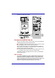
Using the Remote Controller, AV Buttons and QosmioPlayer The figure below shows the buttons on the Remote Controller. Refer to the descriptions on the next pages for the functions of each button. Power Record Stop Play Pause Rewind Forward Replay Skip Back More info OK Arrows Volume + Channel/Page Volume Recorded TV Start Mute DVD Menu Live TV Guide Remote Controller for models with Windows XP Media Center Edition User’s Manual Power Starts or ends the operating system session.
Using the Remote Controller, AV Buttons and QosmioPlayer User’s Manual Rewind Rewinds the currently selected media (video, DVD, music, etc). Play Plays the selected media. Fast forward Fast forwards the currently selected media (video, DVD, music, etc). Replay Moves the currently selected media backward, seven seconds for videos and live TV, one music track or one DVD chapter. Pause Pauses an audio or video track, and live or recorded TV programs.
Using the Remote Controller, AV Buttons and QosmioPlayer User’s Manual Mute Turns your computer sound off. Channel/Page up(+) and down(-) Changes the TV channel or moves a page up and down, depending on the available options. DVD Menu Opens the main menu on a DVD movie, if available. Recorded TV Opens the Recorded TV feature in Windows Media Center mode. This feature is not supported in QosmioPlayer mode.
Using the Remote Controller, AV Buttons and QosmioPlayer Functions via the Remote Controller and the keyboard in the QosmioPlayer mode The list shows how the functions available from the keyboard correspond to those available from the Remote Controller in the QosmioPlayer mode. Note that some functions via the Remote Controller in the list may not be supported by the Remote Controller you are using. Check the model and specifications of your Remote Controller before use.
Using the Remote Controller, AV Buttons and QosmioPlayer 3 Select channel 3 Select track 3 Select chapter 3 4 Select channel 4 Select track 4 Select chapter 4 5 Select channel 5 Select track 5 Select chapter 5 6 Select channel 6 Select track 6 Select chapter 6 7 Select channel 7 Select track 7 Select chapter 7 8 Select channel 8 Select track 8 Select chapter 8 9 Select channel 9 Select track 9 Select chapter 9 1, 0 Select channel 10 Select track 10 Select chapter 10 0 - No
Using the Remote Controller, AV Buttons and QosmioPlayer Volume - Mute Ctrl + Decreases the volume Decreases the volume Decreases the volume M Mute the volume Mute the volume Mute the volume - Rewinds by about 10 seconds Rewinds the media quickly - Skip by about 10 seconds Forwards the media quickly Space - Play or pauses Play or pauses Ctrl + Space - Stop Stop Ctrl + R - Repeat - Ctrl + S - Shuffle - D Display the channel status Display the title status Displays the titl
Using the Remote Controller, AV Buttons and QosmioPlayer AV Buttons function This section describes the functions of the AV buttons in the Windows mode and QosmioPlayer mode. Windows mode TV tuner model Ten buttons are available for use: TV, CD/DVD, Play/Pause, Stop, Previous, Next, Record, Brightness, Monitor-in, TV-out. These buttons allow you to manage Audio/Video, run applications and access utilities.
Using the Remote Controller, AV Buttons and QosmioPlayer Brightness button Use this button to adjust the brightness of the built-in LCD. Monitor-in button Pressing this button will toggle mode between Windows and AV Input. In Monitor mode, both DVD/CD and Digital Audio indictors are on and the Audio button is disabled. Pressing this button in the power-off condition will do nothing. TV-out button Pressing this button while Windows is running will switch the display to an attached TV.
Using the Remote Controller, AV Buttons and QosmioPlayer Previous button Press this button to advance to the previous track, chapter or data. Next button Press this button to advance to the next track, chapter or data. TV-out button Pressing this button while Windows is running will switch the display to an attached TV. The TVout button can be programmed by using the apropriate Windows utility to allow the configuration of specific options.
Using the Remote Controller, AV Buttons and QosmioPlayer Brightness Changes the brightness level of Changes the brightness level of LCD; 1->2->···8->1 LCD; 1->2->···8->1 Monitor-in (TV tuner model only) Switch LCD display to TV/TV input Switch LCD display to TV/TV input QosmioPlayer The section describes the QosmioPlayer. Qosmio Engine You are able to enjoy vivid and striking visuals through the full-screen capability of WinDVD and the Qosmio Engine feature of QosmioPlayer.
Using the Remote Controller, AV Buttons and QosmioPlayer Restrictions of the QosmioPlayer The current mode will be maintained and restored the next time the computer is switched on or is restarted from either Standby Mode or Hibernation Mode. The Qosmio Engine is available only for the LCD and has the following restrictions. ■ Qosmio does not support LCD/CRT, CRT, TV, LCD/TV and MultiMonitor. ■ Depending on the video being played, noise may be present: ■ When DVD is played with WinDVD.
Using the Remote Controller, AV Buttons and QosmioPlayer ■ Windows sounds are still heard even when the mode has been switched to Monitor-in. ■ Fn+F1/Fn+F5 are not available. ■ With the Monitor-in mode, the screens of other applications will be invisible.This condition may cause you to operate an application incorrectly by pressing a mouse button or any key on the keyboard. To prevent operational errors, it is recommended to perform the following: ■ Close any applications running on your system.
Using the Remote Controller, AV Buttons and QosmioPlayer Using the Remote Controller The Remote Controller is only provided with the TV Tuner models. This computer includes a remote controller that allows you to perform some functions without getting up and using the computer. The Remote Controller is designed specifically for this computer. Some application programs may not support remote control functions.
Using the Remote Controller, AV Buttons and QosmioPlayer 2. Connect the external remote control receiver to one of the computer's USB ports. USB port Connecting the USB cable to the computer’s USB port 3. Connect the infrared transmitter cable to the external remote control receiver. Please note that your satellite dish or cable TV remote control must be compatible in order for it to function.
Using the Remote Controller, AV Buttons and QosmioPlayer Operational range of the remote control Remote Controller is provided with some models. Point the remote control at your computer and press a button. The operational angle and distance are described below. Distance Within 5 m from the infrared receiver window. Angle Within about 30 degrees horizontally and about 15 degrees vertically of perpendicular to the infrared receiver window.
Using the Remote Controller, AV Buttons and QosmioPlayer Installing/Removing batteries Please ensure that you have installed the batteries provided with this product before using the Remote Controller. The procedures for installing and removing the battery vary depending on the type of the Remote Controller. Check the type and then install or remove the battery as instructed. Store the battery for the remote control beyond the reach of children. If a child swallows a battery, this might result in choking.
Using the Remote Controller, AV Buttons and QosmioPlayer Remote Controller Type of battery that can be used for the Remote Controller When the batteries shipped with the Remote Controller has discharged replace it with a single CR2025 (or equivalent) Ni-MH battery. Other types or battery cannot be used. If you use the product for the first time, you may see an insulating seal on the battery terminal. If this is the case, remove it to begin using the remote control.
Using the Remote Controller, AV Buttons and QosmioPlayer Battery holder Battery Removing the battery 3. Replace the battery with a new one. Reinstall the battery holder. Close the Battery holder securely until it clicks.
Using the Remote Controller, AV Buttons and QosmioPlayer Switching video Input Follow the steps below to define the Monitor Input feature that allows video from a device such as an analog camera or game machine to be displayed on the LCD of your computer. This product supports several screen mode switching modes. When you select a mode that provides an aspect ratio different from that supported by software, for example TV mode, video may be displayed differently from the original.
Using the Remote Controller, AV Buttons and QosmioPlayer 2. Click the Monitor Input Settings button in the TOSHIBA Picture Enhancement Utility window. The Monitor Input Settings window appears. Monitor Input Settings window 3. Select the item for the Terminal Shape. ■ Select the S-Video item for the Terminal Shape. (Using the S-Video-in port for video input) ■ Select the Monitor-in item for the Terminal Shape. (Using the Monitor-in port for video input) 4. Select the NTSC or PAL item for the TV Standard.
Qosmio G10 Chapter 9 Optional Devices Optional devices can expand the computer’s capabilities and its versatility.
Optional Devices PC Card The computer is equipped with a PC Card slot that can accommodate one 5 mm Type II card. Any PC Card that meets industry standards either manufactured by TOSHIBA or other vendor can be installed. The slot supports 16-bit PC Cards, including PC Card 16’s multifunction card and CardBus PC cards. CardBus supports the new standard of 32-bit PC Cards. The bus provides superior performance for the greater demands of multimedia data transmission.
Optional Devices 4. Press the PC Card eject button to pop the PC Card out slightly. 5. Grasp the PC Card and draw it out. PC Card PC Card Eject button Removing the PC Card Bridge media slot This slot lets you insert SD card, Memory Stick (Pro), xD picture card and MultiMediaCard devices. This Bridge media slot supports the following cards.
Optional Devices SD memory cards comply with SDMI (Secure Digital Music Initiative), which is a technology adopted to prevent unlawful copy or playback of digital music. For this reason, you cannot copy or playback protected material on another computer or other device. You may not use the reproduction of any copyrighted material except for your personal enjoyment. Formatting an SD card SD memory cards are sold with format in conformity to the Standards of SD memory card.
Optional Devices Removing an SD card To remove an SD card, follow the steps below. 1. Open the Safely Remove Hardware icon on the Task Bar. 2. Point to Safely Remove Secure Digital Storage Device-Drive (X:) and click. 3. Push in the card and release it to pop the card out slightly. 4. Grasp the card and remove it. Bridge media indicator SD card Bridge media slot Removing an SD card ■ Make sure the indicator is out before you remove the SD card or turn off the computer’s power.
Optional Devices Memory Stick/Memory Stick Pro The computer is equipped with a Bridge media slot that can accommodate Memory Stick flash memory cards with various memory capacities. Memory Stick lets you easily transfer data from devices, such as digital cameras and Personal Digital Assistants, that use Memory Stick flash memory. Keep foreign objects out of the Bridge media slot. A pin or similar object can damage the computer’s circuitry. ■ The slot does not support Magic Gate functions.
Optional Devices Do not remove a Memory Stick while the computer is in Standby Mode or Hibernation Mode. The computer could become unstable or data in the Memory Stick could be lost. xD picture card The computer is equipped with the Bridge media slot that can accommodate xD picture cards with various memory capacities. The xD picture card let you easily transfer data from devices, such as digital cameras that use xD picture card flash-memory. Keep foreign objects out of the Bridge media slot.
Optional Devices 3. Do not expose memory cards to liquids or store in humid areas or lay media close to containers of liquid. 4. Do not touch the metal part of a memory card or expose it to liquids or let it get dirty. 5. After using the memory card, return it to its case. For more details on using memory cards, see manuals accompanying the cards.
Optional Devices Removing a MultiMediaCard To remove a MultiMediaCard, follow the steps below. 1. Open the Safely Remove Hardware icon on the Task Bar. 2. Point to Safely Remove Secure Digital Storage Device-Drive (X:) and click. 3. Push in the card and release it to pop the card out slightly. 4. Grasp the card and remove it.
Optional Devices Memory expansion You can install additional memory in the computer’s memory module socket to increase the amount of RAM. This section describes how to install and remove a memory module. ■ Use only memory modules approved by TOSHIBA. ■ Do not try to install or remove a memory module under the following conditions. You can damage the computer and the module. Also, data will be lost. a. The computer is turned on. b. The computer was shut down using either Standby Mode or Hibernation Mode. c.
Optional Devices 5. Slide your fingernail or a thin object under the cover and lift it off. Screw Memory module cover Removing the memory module cover 6. Fit the memory module’s connectors into the socket at about a 45 degree angle and push the module down until latches on either side snap into place. Slot B Slot A Seating the memory module ■ Be careful not to drop the screw inside the computer. ■ Do not touch the connectors on the memory module or on the computer.
Optional Devices 3. Turn the computer upside down and remove the battery pack. Refer to Replacing the battery pack section in Chapter 6, Power, for details. 4. Loosen the screw securing the memory module cover. The screw is attached to the cover to prevent it from being lost. 5. Slide your fingernail or a thin object under the cover and lift it off. 6. Push the latches to the outside to release the module. A spring will force one end of the module up. 7. Grasp the module by the sides and pull it out.
Optional Devices Battery charger The battery charger provides a convenient way to charge battery packs without requiring the use of your computer. The battery charger holds up to two lithium ion battery packs. USB floppy disk drive The USB floppy disk drive module can be connected to the USB port. For details on connecting the USB floppy disk drive module, refer to Chapter 4, Operating Basics. External monitor An external analog monitor can be connected to the external monitor port on the computer.
Optional Devices Installation Connection via the S-Video out port 1. Plug one end of the S-Video out cable into the S-Video out port of your computer. S-Video out port Connecting the S-Video out port 2. Insert the other end of the S-Video out cable into the S1-/S2 video input of the TV set. You can use your computer’s speakers or a set of headphones to get sound. Connection via the D-Video out port 1. Plug one end of the D-Video out cable into the D-Video out port of your computer.
Optional Devices Settings for display video on TV To view video on the TV set, be sure to configure the following settings. If not, nothing will be displayed on the TV screen. ■ Be sure to select the display device on which the video image is to be displayed before commencing playback. Do not change the display device while playing a video. ■ Do not change the display device under the following conditions.
Optional Devices Monitor-in Set up Terminal Shape before connecting with Monitor-in port. Refer to the section Switching video Input in Chapter 8, Using the Remote Controller, AV Buttons and QosmioPlayer for details. Model with the TV Tuner The Monitor-in feature allows you to connect the following devices to display video on the built-in LCD.
Optional Devices 3. Insert the plugs at the other end of the output cable of the device you wish to use into the output terminals of that device. 4. Power on the device you wish to use (connected via the output cable). 5. Press the power button of your computer to turn it on. When you press the power button, Windows starts. If a music CD or DVD video disk is present in the drive, automatic play is activated. In that case, cancel it. 6. Press the computer’s Monitor-in button.
Optional Devices 2. Insert the corresponding plugs of the audio cable into the sound input terminals (red: sound, right channel, white: sound, left channel) of the Monitor-in cable. Sound right input (red) red Sound left input (white) white Connecting the cable 3. Insert the other end of the audio cable into the line out port of the audio device.
Optional Devices S-Video-in port Connecting the S-Video-in port 2. Insert the other end of the S-Video-in cable into the output port of the analog device you wish to connect. To hear sounds, use a video cable to connect the sound terminals of the audio device and your computer (red: sound, right channel, white: sound, left channel). After connecting an analog video camera or a video deck to your computer, run WinDVR. WinDVR is started by selecting Start -> All Programs -> InterVideo WinDVR.
Optional Devices ■ Do not transfer data in areas where static electricity is easily generated or in areas subjected to electronic noise. Data can be destroyed. ■ If you are transferring data through an IEEE1394 hub, do not connect or disconnect other devices from the hub during data transfer. There is a likelihood that data will be damaged. Connect all devices to the hub before you turn on the computer’s power.
Optional Devices Disconnecting 1. Open the Safety Remove Hardware icon on the Task Bar. 2. Point to i.LINK (IEEE1394) device and click. 3. Disconnect the cable from the computer then from the i.LINK device. Refer also to the documentation that came with your i.LINK device. Security lock Security locks enable you to anchor your computer a desk or other heavy object to help prevent unauthorized removal of the computer.
Qosmio G10 Chapter 10 Troubleshooting TOSHIBA designed the computer for durability. However, should problems occur, following the procedures in this chapter can help to determine the cause. All readers should become familiar with this chapter. Knowing what might go wrong can help prevent problems from occurring. Problem solving process Resolving problems will be much easier if you observe the following guidelines: ■ Stop immediately when you recognize a problem exists.
Troubleshooting Preliminary checklist Consider the simplest solution first. The items in this checklist are easy to fix and yet can cause what appears to be a serious problem. ■ Make sure you turn on all peripheral devices before you turn on the computer. This includes your printer and any other external device you are using. ■ Before you attach an external device, turn the computer off. When you turn the computer back on it recognizes the new device.
Troubleshooting Software Hardware The problems may be caused by your software or disk. If you cannot load a software package, the media may be damaged or the program might be corrupted. Try loading another copy of the software. If an error message appears while you are using a software package, check the software documentation. These documents usually include a problem solving section or a summary of error messages. Next, check any error messages in the operating system documentation..
Troubleshooting Self test When the computer starts up, the self test will be run automatically, and the following will be displayed: S This message remains on the screen for a few seconds. If the self test is successful, the computer tries to load the operating system, depending on how the Boot Priority is set in the TOSHIBA HW Setup program.
Troubleshooting AC power If you have trouble turning on the computer with the AC adaptor connected, check the DC IN indicator. Refer to Chapter 6, Power of your online manual for more information. Problem Procedure AC adaptor doesn’t power the computer (DC IN indicator does not glow green) Check the connections. Make sure the cord is firmly connected to the computer and a power outlet. Check the condition of the cord and terminals. If the cord is frayed or damaged, replace it.
Troubleshooting Problem Procedure Unplug the AC adaptor and remove the battery to make sure the terminals are clean. If necessary wipe them with a soft dry cloth dipped in alcohol. Connect the AC adaptor and replace the battery. Make sure it is securely seated. Check the Battery indicator. If it does not glow, let the computer charge the battery for at least 20 minutes.
Troubleshooting Keyboard Keyboard problems can be caused by your setup configuration. For more information refer to Chapter 5, The Keyboard of your online manual. Problem Procedure Some letter keys produce numbers Check that the numeric keypad overlay is not selected. Press Fn + F10 and try typing again. Output to screen is garbled Make sure the software you are using is not remapping the keyboard. Remapping involves reassigning the meaning of each key. See your software’s documentation.
Troubleshooting Problem Procedure Slow performance Your files may be fragmented. Run Disk Defragmenter to check the condition of your files and disk. Refer to your operating system documentation or online HELP for information on running Disk Defragmenter. As a last resort, reformat the hard disk. Then, reload the operating system and other files. If problems persist, contact your dealer. DVD-ROM&CD-R/RW drive For more information, refer to Chapter 4, Operating Basics.
Troubleshooting Problem Procedure Cannot write correctly If you have trouble writing, make sure you are observing the following precautions: ■ Use only media recommended by TOSHIBA. ■ Do not use the mouse or keyboard during writing. ■ Use only the software supplied with the computer for recording. ■ Do not run or start other software during writing. ■ Do not jar the computer during writing. ■ Do not connect/disconnect external devices or install/remove internal cards during writing.
Troubleshooting Check the type of CD/DVD you are using. The drive supports: DVD-ROM: DVD-ROM, DVD-Video, DVD- R, DVD-RW, DVD+R, DVD+RW, DVD-RAM CD-ROM: CD-DA, CD-Text, Photo CD (single/multi-session), CD-ROM Mode 1, Mode 2, CD-ROM XA Mode 2 (Form1, Form2), Enhanced CD (CD-EXTRA), Addressing Method 2 Check the region code on the DVD. It must match that on the DVD Super Multi drive. Region codes are listed in the Optical media drives section in Chapter 2, The Grand Tour.
Troubleshooting SD card Refer also to Chapter 9, Optional Devices of your online manual. Problem Procedure SD card error occurs Reseat the SD card to make sure it is firmly connected. Check the SD card’s documentation. You cannot write to an SD card Make sure the SD card is not write protected. You cannot read a file Make sure the target file is on the SD card inserted in the slot. If problems persist, contact your dealer.
Troubleshooting MultiMediaCard Refer also to Chapter 9, Optional Devices of your online manual. Problem Procedure MultiMediaCard error occurs Reseat the MultiMediaCard to make sure it is firmly connected. Check the MultiMediaCard’s documentation. You cannot write to an MultiMediaCard Make sure the MultiMediaCard is not write protected. You cannot read a file Make sure the target file is on the MultiMediaCard inserted in the slot. If problems persist, contact your dealer.
Troubleshooting Pointing device If you are using a USB mouse, also refer to the USB section in this chapter and to your mouse documentation. Touch Pad Problem Procedure On-screen pointer does not respond to Pad operation The system might be busy. If the pointer is shaped as an hourglass, wait for it to resume its normal shape and try again to move it. Double-tapping does not work Try changing the double-click speed setting in the mouse control utility. 1.
Troubleshooting Problem Procedure The mouse pointer moves too fast or too slow Try changing the speed setting in the mouse control utility. 1. Click start, click Control Panel, select the Mouse icon and press Enter. 2. Click the Pointer Options tab. 3. Set the speed as instructed and click OK. The mouse pointer moves erratically The mouse might be dirty. Refer to your mouse documentation for instructions on cleaning. If problems persist, contact your dealer.
Troubleshooting Sound system Problem Procedure No sound is heard Adjust the volume control dial. Check the software volume settings. Make sure the headphones connection is secure. Monitor Refer also to Chapter 9, Optional Devices, of your online manual and to your monitor’s documentation. Problem Procedure Monitor does not turn on Make sure that the external monitor’s power switch is on. Confirm that the external monitor’s power cable is plugged into a working power outlet.
Troubleshooting Problem Procedure After making a call you can’t hear a ring Make sure the tone or pulse selection in your communications application is set correctly. You can also use the ATD command. Communication is cut off unexpectedly The computer will automatically cut off communication when connection with the carrier is not successful for a set time interval. Try lengthening this time interval.
Troubleshooting TV output signal Problem Procedure Display on TV is poor Make sure the TV type is correct for your area: NTSC (US, JAPAN), PAL or SECAM (Europe). No display Try adjusting the contrast and brightness controls on the external monitor. Press hotkeys Fn + F5 to change the display. Refer to Chapter 5, The Keyboard. If problems persist, contact your dealer.
Troubleshooting TOSHIBA support If you require any additional help using your computer or if you are having problems operating the computer, you may need to contact TOSHIBA for additional technical assistance. Before you call Some problems you experience may be related to software or the operating system, it is important to investigate other sources of assistance first. Before contacting TOSHIBA, try the following: ■ Review troubleshooting sections in the documentation for software and peripheral devices.
Qosmio G10 Appendix A Specifications This appendix summarizes the computer’s technical specifications. Physical Dimensions Weight (typical) 3.7 kilograms, configured with: Pentium-M processor 2.0 GHz, 17.0” WXGA+, 1024MB+1024MB RAM, 100GB+100GB HDD, DVD Super Multi drive, TV tuner, LAN, Wireless LAN Intel-abg, BT. Size 406 (w) × 285 (d) × 37.5/43.
Specifications Power Requirements AC adaptor 100-240 volts AC 50 or 60 hertz (cycles per second) Computer 15 VDC 8.0 amperes Built-in Modem Network control unit (NCU) Type of NCU AA Type of line Telephone line (analog only) Type of dialing Pulse Tone Control command AT commands EIA-578 commands Monitor function Computer’s speaker Communication specifications User’s Manual Communication system Data: Fax: Full duplex Half duplex Communication protocol Data ITU-T-Rec (Former CCITT) V.
Specifications User’s Manual Communication speed Data transmission and reception 300/1200/2400/4800/7200/9600/12000/14400/ 16800/19200/21600/24000/26400/28800/31200/ 33600 bps Data reception only with V.
Qosmio G10 Appendix B Display Controller and Modes Display controller The display controller interprets software commands into hardware commands that turn particular picture elements (pels) on or off. The controller is an advanced Video Graphics Array (VGA) that provides Super VGA (SVGA) and Extended Graphics Array (XGA) support for the internal LCD and External monitors. A high-resolution external monitor connected to the computer can display up to 2048 horizontal and 1536 vertical pixels at 16 M colours.
Display Controller and Modes Table1 Video modes (VGA) LCD colours CRT colours Scanning frequency Vertical (Hz) 8×8 16 of 256K 16 of 256K 70 80 × 25 Characters 8×8 16 of 256K 16 of 256K 70 VGA Text 40 × 25 Characters 8 × 14 16 of 256K 16 of 256K 70 2*, 3* VGA Text 80 × 25 Characters 8 × 14 16 of 256K 16 of 256K 70 0+, 1+ VGA Text 40 × 25 Characters 9 × 16 16 of 256K 16 of 256K 70 2+, 3+ VGA Text 80 × 25 Characters 9 × 16 16 of 256K 16 of 256K 70 4, 5 VGA Grph 320 × 2
Display Controller and Modes Table1 Video modes (VGA) continued Video mode Type LCD colours CRT colours Scanning frequency Vertical (Hz) D VGA Grph 320 × 200 Pels 8×8 16 of 256K 16 of 256K 70 E VGA Grph 640 × 200 Pels 8×8 16 of 256K 16 of 256K 70 F VGA Grph 640 × 350 Pels 8 × 14 Mono Mono 70 10 VGA Grph 640 × 350 Pels 8 × 14 16 of 256K 16 of 256K 70 11 VGA Grph 640 × 480 Pels 8 × 16 2 of 256K 2 of 256K 60 12 VGA Grph 640 × 480 Pels 8 × 16 16 of 256K 16 of 256K
Display Controller and Modes Table 2 Video modes (SVGA) Vertical Frequency can be set up when outputting to External Monitor..
Display Controller and Modes Table 2 Video modes (SVGA) continued Resolution LCD colours CRT colours Vertical frequency (Hz) 640 × 480 64K/64K 64K/64K 60 75 85 100 800 × 600 64K/64K 64K/64K 60 75 85 100 1024 × 768 64K/64K 64K/64K 60 75 85 100 1280 × 1024 (Virtual)* 64K/64K 64K/64K 60 75 85 100 1440 × 900 64K/64K 64K/64K 60 75 85 100 1600 × 1200 (Virtual)* 64K/64K 64K/64K 60 75 85 100 1920 × 1440 (Virtual)* 64K/64K 64K/64K 60 75 85 2048 × 1536 (Virtual)* 64K/64K 64K/64K 60
Display Controller and Modes Table 2 Video modes (SVGA) continued Resolution LCD colours CRT colours Vertical frequency (Hz) 640 × 480 16M/16M 16M/16M 60 75 85 100 800 × 600 16M/16M 16M/16M 60 75 85 100 1024 × 768 16M/16M 16M/16M 60 75 85 100 1280 × 1024 (Virtual)* 16M/16M 16M/16M 60 75 85 100 1440 × 900 16M/16M 16M/16M 60 75 85 100 1600 × 1200 (Virtual)* 16M/16M 16M/16M 60 75 85 100 1920 × 1440 (Virtual)* 16M/16M 16M/16M 60 75 2048 × 1536 (Virtual)* 16M/16M 16M/16M 60 75
Qosmio G10 Appendix C Wireless LAN This appendix is intended to help you get your Wireless LAN network up and running, with a minimum of parameters. Card Specifications Form Factor Mini PCI TypeIII Compatibility Network Operating System Media Access Protocol Data Rate ■ IEEE 802.11 Standard for Wireless LANs ■ Wi-Fi (Wireless Fidelity) certified by the Wi-Fi Alliance. The ‘Wi-Fi CERTIFIED’ logo is a certification mark of the Wi-Fi Alliance.
Wireless LAN Wireless communication is often subject to local radio regulations. Although Wireless LAN wireless networking products have been designed for operation in the license-free 2.4GHz and 5GHz band, local radio regulations may impose a number of limitations to the use of wireless communication equipment. Refer to the sheet “Information to the User” for regulatory information that may apply in your country/region.
Wireless LAN 6 2437 7 2442 8 2447 9 2452 10 2457*1 11 2462 12 2467*2 13 2472*2 Wireless IEEE 802.11 Channels Sets (Turbo Mode) Frequency Range Channel ID 2400-2483.5 MHz Note 6 2437 US only*4 When installing Wireless LAN cards, the channel configuration is managed as follows: ■ For wireless clients that operate in a Wireless LAN Infrastructure, the Wireless LAN card will automatically start operation at the channel identified by the Wireless LAN Access Point.
Wireless LAN 48 5240 52 5260 56 5280 60 5300 64 5320 100 5500*3 104 5520*3 108 5540*3 112 5560*3 116 5580*3 120 5600*3 124 5620*3 128 5640*3 132 5660*3 136 5680*3 140 5700*3 149 5745*3 US only *4 153 5765*3 US only *4 157 5785*3 US only *4 161 5805*3 US only *4 Wireless Channels Sets (Turbo Mode) User’s Manual Frequency Range Channel ID 5150-5850 MHz Note 42 5210*3 US only *4 50 5250*3 US only *4 C-4
Wireless LAN 58 5290*3 US only *4 152 5760*3 US only *4 160 5800*3 US only *4 *1 Factory-set default channels *2 Refer to the sheet Approved Countries/Regions for use for the countries/ regions that in which these channels can be used. *3 These channels are available to A/B/G combo type only. *4 Available Area: US (USA, CANADA) only.
Qosmio G10 Appendix D AC Power Cord and Connectors The power cord’s AC input plug must be compatible with the various international AC power outlets and the cord must meet the standards for the country/region in which it is used. All cords must meet the following specifications: Length: Minimum 2 meters Wire size: Minimum 0.75 mm2 Current rating: Minimum 2.5 amperes Voltage rating: 125 or 250 VAC (depending on country/region’s power standards) Certification agencies U.S.
AC Power Cord and Connectors France: UTE Switzerland: SEV Germany: VDE United Kingdom: BSI In Europe, power cords must be VDE type, H05VVH2-F and two conductors. For the United States and Canada, plug configuration must be a 2-15P (250 V) or 1-15P (125 V) as designated in the U.S. National Electrical code handbook and the Canadian Electrical Code Part II. The following illustrations show the plug shapes for the U.S.A. and Canada, the United Kingdom, Australia and Europe.
Qosmio G10 Appendix E Usage Restrictions This appendix describes the Usage Restrictions. ■ This configuration is designed to work with a signal from a conventional (standard or analog) TV antenna. ■ TOSHIBA does not guarantee that signals received by satellite or cable TV receivers will work properly and does not provide technical support for them. ■ The TOSHIBA Qosmio’s AC power adaptor must be connected to get the best possible audio and video performance.
Qosmio G10 Appendix F If your computer is stolen Always take care of your computer and try to prevent it from being stolen. You are the owner of a valuable technical device, which may be highly attractive to thieves, so please do not leave it unattended in a public place. To further help protect against theft, security cables can be bought for use with your notebook when it is being used at home or in the office.
If your computer is stolen TOSHIBA Theft Registration Send to: TOSHIBA Europe GmbH Technical Service and Support Leibnizstr. 2 93055 Regensburg Germany Fax number: +49 (0) 941 7807 921 Country stolen: Machine type: (e.g. Qosmio G10) Model number: (e.g. PSA50 YXT) Serial number: (e.g.
Qosmio G10 Glossary The terms in this glossary cover topics related to this manual. Alternate naming is included for reference.
Glossary I/O: input/output IrDA: Infrared Data Association IRQ: interrupt request KB: kilobyte LCD: liquid crystal display LED: light emitting diode LSI: large scale integration MB: megabyte OCR: optical character recognition (reader) PCB: printed circuit board PCI: peripheral component interconnect RAM: random access memory RGB: red, green, and blue ROM: read only memory RTC: real time clock SCSI: small computer system interface SIO: serial input/output SXGA+: super extended graphics array plus TFT: thin-
Glossary ANSI: American National Standards Institute. An organization established to adopt and define standards for a variety of technical disciplines. For example, ANSI defined the ASCII standard and other information processing requirements. antistatic: A material used to prevent the buildup of static electricity. application: A group of programs that together are used for a specific task such as accounting, financial planning, spreadsheets, word processing and games.
Glossary byte: The representation of a single character. A sequence of eight bits treated as a single unit; also the smallest addressable unit within the system. C cache memory: High speed memory which stores data that increases processor speed and data transfer rate. When the CPU reads data from main memory, it stores a copy of this data in cache memory. The next time the CPU needs that same data, it looks for it in the cache memory rather than the main memory, which saves time.
Glossary compatibility: 1) The ability of one computer to accept and process data in the same manner as another computer without modifying the data or the media upon which it is being transferred. 2) the ability of one device to connect to or communicate with another system or component. components: Elements or parts (of a system) which make up the whole (system). Composite Video (YUV): A standard video signal used to transmit images, e.g. from a VCR to a TV.
Glossary default: The parameter value automatically selected by the system when you or the program do not provide instructions. Also called a preset value. delete: To remove data from a disk or other data storage device. Synonymous with erase. device driver: A program that controls communication between a specific peripheral device and the computer. The CONFIG.SYS file contains device drivers that MS-DOS loads when you turn the computer on.
Glossary E echo: To send back a reflection of the transmitted data to the sending device. You can display the information on the screen, or output it to the printer, or both. When a computer receives back data it transmitted to a CRT (or other peripheral device) and then retransmits the data to printer, the printer is said to echo the CRT. erase: See delete. escape: 1) A code (ASCII code 27), signaling the computer that what follows are commands; used with peripheral devices such as printers and modems.
Glossary H hard disk: A non-removable disk usually referred to as drive C. The factory installs this disk and only a trained engineer can remove it for servicing. Also called fixed disk. hard disk drive (HDD): An electromechanical device that reads and writes a hard disk. See also hard disk. hardware: The physical electronic and mechanical components of a computer system: typically, the computer itself, external disk drives, etc. See also software and firmware.
Glossary IrDA 1.1: An industry standard that enables cableless infrared serial data transfer at speeds of up to 4 Mbps. J jumper: A small clip or wire that allows you to change the hardware characteristics by electrically connecting two points of a circuit. K K: Taken from the Greek word kilo, meaning 1000; often used as equivalent to 1024, or 2 raised to the 10th power. See also byte and kilobyte. KB: See kilobyte.
Glossary microprocessor: A hardware component contained in a single integrated circuit that carries out instructions. Also called the central processing unit (CPU), one of the main parts of the computer. mode: A method of operation, for example, the boot mode, Standby Mode or the Hibernation Mode. modem: Derived from modulator/demodulator, a device that converts (modulates) digital data for transmission over telephone lines and then converts modulated data (demodulates) to digital format where received.
Glossary P PAL: PAL (Phase Alternating Line) is the dominant video and broadcasting standard in Europe. parity: 1) The symmetrical relationship between two parameter values (integers) both of which are either on or off; odd or even; 0 or 1. 2) In serial communications, an error detection bit that is added to a group of data bits making the sum of the bits even or odd. Parity can be set to none, odd, or even. password: A unique string of characters used to identify a specific user.
Glossary R Radio frequency interference (RFI) shield: A metal shield enclosing the printed circuit boards of the printer or computer to prevent radio and TV interference. All computer equipment generates radio frequency signals. The FCC regulates the amount of signals a computing device can allow past its shielding. A Class A device is sufficient for office use. Class B provides a more stringent classification for home equipment use.
Glossary software: The set of programs, procedures and related documentation associated with a computer system. Specifically refers to computer programs that direct and control the computer system’s activities. See also hardware. stop bit: One or more bits of a byte that follow the transmitted character or group codes in asynchronous serial communications. subpixel: Three elements, one red, one green and blue (RGB), that make up a pixel on the colour LCD.
Glossary W warm start: Restarting or resetting a computer without turning it off. window: A portion of the screen that can display its own application, document or dialog box. Often used to mean a Microsoft Windows window. Wireless LAN: Local Area Network (LAN) through wireless communication. write protection: A method for protecting a floppy disk from accidental erasure.
Qosmio G10 Index A D AC adaptor 1-4 additional 1-15, 9-12 connecting 3-4 DC IN 15V port 2-6 ASCII characters 5-9 AV Buttons 8-9 DC IN indicator 2-11, 6-3 Display 1-7, 2-9 automatic power off 1-10 brightness decreases 5-5 controller 1-7, B-1 hinge 2-9 opening 3-5 DLA for TOSHIBA 1-14, 4-16 Documentation list 1-3 DVD Super Multi drive 1-6 location 2-4 using 4-3 DVD-ROM&CD-R/RW drive 1-5 location 2-4 using 4-3 writing 4-10 B Battery charging 6-8 extending battery life 6-11 indicator 2-11, 6-3 location 2-8
Index F K Floppy disk 1-5 additional 9-13 using 4-2 Fn + Ctrl (enhanced keyboard’s simulation) Keyboard 1-7, 5-1 emulating keys on enhanced 5-2 F1 ...
Index P Password power on 1-11 problems 10-6 starting the computer by 6-16 user 6-14 PC card 1-7, 9-2 inserting 9-2 location of slot 2-2 removing 9-2 Ports 1-7 external monitor 1-7 i.
Index T V TOSHIBA PC DiagnosticTool 1-14 TOSHIBA Power Saver 1-12 TOSHIBA Theft Registration F-2 TOSHIBA Zooming Utility 1-13 Touch Pad 1-7 location 2-9 using 4-1 TV Tuner 1-9, 4-6 TV 9-13 Video modes B-1 Video RAM 1-4 W Wireless communication switch 4-25 indicator 4-25 Wireless LAN 1-10 using 4-24 Wireless TV Tuner 9-21 U USB 1-7 location 2-2, 2-5 User’s Manual Index-4