
User Guide


4.11 Cover assembly 4 Replacement Procedures
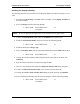
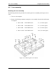
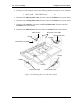
4. Turning over the computer, remove the following screws securing the cover assembly.
• M2.5×8.0B FLAT BIND screw x3
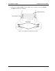
5. Disconnect the SD board flat cable from the connector CN9500 on the system board.
6. Disconnect the touch pad flat cable from the connector CN3201 on the system board.
7. Turning up the insulator, disconnect the LE board flat cable from the connector
CN9660 on the system board
8. Disconnect the MDC harness from the connector CN3021 on the system board
MDC harness
M2.5x8.0B FLAT BIND
CN9500
SD board flat cable
CN3021
M2.5x8.0B FLAT BIND
CN3201
Insulator
CN9660
Touch
p
ad flat cable
LE board flat cable
Figure 4-23 Removing the screws & cables (front)
4-36 QOSMIO G10 Maintenance Manual (960-497)