
Operation Manual


1918
Preparations
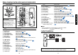
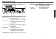
Parts on the rear panel
(4) (6)(3)(2) (5) (7)
(9) (10)
(1)
(11)
(8)
Name : Main Function
(9) VIDEO IN terminal
S-VIDEO : Input S video signals from video equipment.
AUDIO (L/R) : Input audio signals from video equipment.
VIDEO : Input video signals from video equipment.
AUDIO (L/R) : Input audio signals from video equipment.
(
10
)AC IN socket : Connect the supplied power cord here.
(
11
) Main power switch : AC power line ON (standby)/OFF.
Name : Main Function
(1) Infrared remote sensor : Senses commands from the remote control.
p.20
(2) CONTROL terminal
LAN : Connects a network cable.
RS232C : When operating the projector via a computer, connect
this to the controlling computer’s RS-232C port.
p.59
(3) COMPUTER (Y/PB/PR) 2 IN terminal
RGB : Input analog RGB signal from a computer or other
source, or a component video signal (Y/P
B/PR) from
video equipment.
AUDIO : Input audio signals.
(4) COMPUTER (Y/P
B/PR) 1 IN terminal
DVI-I : Input analog or digital RGB signal from a computer, or
a component video signal (Y/P
B/PR) from video
equipment.
AUDIO : Input audio signals.
(5) MONITOR terminal : Connect to a computer display, etc.
(6) AUDIO OUT terminal : Outputs audio signals.
(7) COMPUTER (Y/P
B/PR) 3 IN terminal
BNC : Input G/B/R/HD/VD signal from a computer, or a
component video signal (Y/P
B/PR) from video
equipment.
AUDIO : Input audio signals.
(8) CAMERA POWER terminal : DC power supply terminal (+15 V). Reserved for future
use.