
Phau Ntawv Qhia


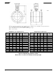

TIC-LF654T
10
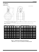
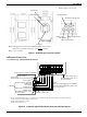
● Separate type LF654/LF622F flowmeters
Grounding with 100Ω or less
ground resistance
Instrument panel : Ordered separately
I/O cable
Grounding with 100Ω or less
ground resistance
Ⅳ wire 5.5mm
2
or more
Current output (4~20mAdc)
Power supply
Power cable
Digital input
(20~30Vdc)
Signal common for DI and DO
Digital output 1
Digital output 2
Grounding with 100Ω or less
ground resistance
or Modbus
Signal cable
(2-wire shielded hard-rubber sheathed cable)
Connected detector
Excitation cable
(3-wire shielded Chloroprene rubber cable)
Thick walled steel conduit
Power switch
(External double-pole power switch)
Figure 9. Separate type LF654/LF622F flowmeters wiring Diagram
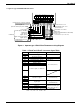
Table 1. LF620F and LF622F Converters Signal Table
Symbol
Description
Cable
L1 (+)
Power supply
Power cable (CVV)
L2 (-)
GND
Ground (for arrester)
FG
Frame ground
DI
Digital Input (20~30Vdc)
I/O cable (CVV-S)
DO1
Digital Output 1
DO2
Digital Output 2
COM
Signal Common for DI, DO1, DO2
+
Current Output (4~20mAdc)
-
X
Excitation Output
Excitation cable
(for LF622F only)
Y
E
A
Signal Input
Signal cable
(for LF622F only)
B
G
T+
Modbus(+)
Twisted-pair polyethylene
insulated vinyl sheath cable
(JKEV,AWG24(0.2mm
2
))
T-
Modbus(-)
TG
Modbus(GND)
Note: Symbol of the terminal is changed as follows for Modbus.
DO2 → T+, DI → T-, COM → TG