
Phau Ntawv Qhia


TIC-LF654T
3
316L stainless steel (std. for PU lining)
Hastelloy C equivalent (std. for PFA lining)
Note: Electrodes are mechanically buffed and
electro-chemically polished.
Grounding rings — 316 stainless steel (std.)
Note: See Table 4 for optional materials and other
related information.
Measuring tube material — 304 stainless steel
Terminal box material — Aluminum alloy (for
separate type)
Coating: Corrosion resistant resin coating (std.)
gray colored
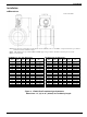
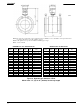
Dimensions and weights: See Figure 3, 4, 5 and 6.
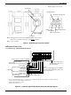
Cable connection port: for separate type detectors.
Cable gland —
LF654(with cFMus):Not provided, 1/2–14NPT
male screws are required.
Model LF620 and LF622 converters
Input signals
Analog signal — the voltage signal from detector,
proportional to process flow rate (for LF622
separate type converter).
Digital input DI
Signal type: 20 to 30Vdc voltage signal
Input resistance: 2.7k
Number of inputs: one point
Note: DI cannot be used with the Modbus communication.
DI function — One of the following functions can
be assigned to the DI signal.
•Range switching — Selects either the higher or
lower range in the unidirectional or bidirectional
2-range setting.
•Totalizer control — ‘Starts/Stops’ or ‘Resets
/Starts’operation in the built-in totalizer.
•Fixed-value outputs —Outputs fixed-values for
current and pulse outputs for loop check.
•Zero adjustment — Executes zero adjustment
(on-stream at zero flow rate).
Output signals
Current output:
4–20mAdc (load resistance 0 to 750)
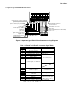
Digital outputs — Two points are available as
follows.
Digital output DO1:
Output type: Transistor open collector
Number of outputs: One point
Output capacity: 30Vdc, 200mA maximum
Note: DO1 cannot be used if Modbus
communication connection is 3 lines.
(Refer table 6 for details)
Digital output DO2 :
Output type:
Solid-state relay output (non polarity)
Number of outputs: One point
Output capacity: 150Vdc, 150mA maximum
or 150Vac (peak to peak), 100mA maximum
Note: DO2 cannot be used with the Modbus
communication. (Refer table 6 for details)
DO1 and DO2 functions — One of the following
functions can be assigned to DO1 and/or DO2 .
• Pulse output (available only for DO1, DO2)
Pulse rate: MAX 10kHz (10000pps)(DO1)
MAX 100Hz (100pps)(DO2)
(Over 1kpps, auto-setting)
Pulse width: 0.3 to 500ms (but it is 40% or less
of the full scale cycle. )
Note: The same and simultaneous pulse is not available
between DO1 and DO2.)
• Multi-range selection outputs (Note 1)
• High, High high, Low, and/or Low low
alarm outputs (Note 2)
• Empty pipe alarm output (Note 2)
• Preset count output
• Converter failure alarm output
Note 1: Two outputs (DO1 and DO2) are needed for 4-range
switching and forward/reverse 2-range switching.
Note 2: Normal Open (default set) or Normal Close is selected
for alarm outputs when programming.
When power failure occurs, unit will be fault to Normal
Open.
Communications output:
• HART (std.) — Digital signal is superimposed on
4–20mAdc current signal as follows:
Conforms to HART protocol
Load resistance: 240 to 750
Load capacitance: 0.25µF maximum
Load inductance: 4mH maximum
• MODBUS (opt.)
Physical layer : RS485
Protocol : Modbus
Mode : RTU
Baudrate : 4800, 9600, 19200bps
Data length : 8bit