
Phau Ntawv Qhia


TIC-LF654T
4
Parity bit : None, Odd, Even
Stop bit : 1bit, 2bit
Error check : CRC-16
Max. station number : 32(with Master device)
Max. cable length : 1.2km (Note)
Note: This length is specification of 3 line
connection.
LCD display:
Full dot-matrix 128×128 dot LCD display
(back–light provided)
A parameter change will rotate the display.
Parameter settings — Parameters can be set as
follows:
• IR Switches: Three key switches are provided
to set configuration parameters.
• Digital communication: HART, or Modbus is
needed to set parameters.
Counter control: If the digital input is set for counter
control, counter control is available for the integrated
value and the pulse output.
Zero adjustment: Zero point adjustment can be
started by pressing the switch in the converter.
Damping: 0.1 , 0.5 to 60 seconds (selectable in one
second increments)
“Converter Field re-verification” Mag-Prover –
Toshiba’s Zero span verification tool allows unit to be
re-verified using an internal software program. The
meter’s excitation current is a NIST traceable
parameter. This parameter can be verified in the field
through the converter to verify the meter is still within
factory calibration. (For more information contact
Toshiba International Corp.)
Conditions when power fails:
Parameter setting values are stored in non–volatile
memory and the values will be restored when the
power returns to normal condition. The outputs
and display will remain as follows when power
fails.
• Current output: 0mAdc
• Digital output: OFF
• LCD display: No display
• HART: No communication
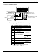
Power supply:
One of the following can be selected:
100 to 240Vac (allowable voltage range: 80 to
264Vac 50/60Hz)
24Vdc (allowable voltage range: 18 to 36Vdc) or
110Vdc (allowable voltage rangel:90 to 130Vdc)
Surge protection:
Arresters are installed in the power supply, digital
input / outputs circuit and current signal output
circuit to help protect the meter from lightning and
improve personnel safety.
Confirmed by following tests
IEC 61000-4-2 Electro static discharge immunity
test
IEC 61000-4- Electrical first transient/burst
immunity test
IEC 61000-4-5 Serge immunity test
Case: Aluminum alloy (equal to IP 67)
Coating:
Acrylic resin-baked coating, pearl–gray colored
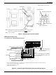
Cable connection port:
Cable glands —
LF620F and LF622F with cFMus Approval:
Not provided, 1/2–14NPT male threads are
required.
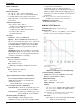
Vibration resistance:
No resonance to the following levels of vibration:
• 10 to 150Hz with acceleration of 9.8m/s
2
• Vibration of 30Hz with 29.4 m/s
2
in 4h in each
direction will not cause any defect to unit.
Note: Avoid using the flowmeter in an environment with
constant vibration.
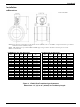
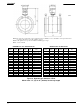
Dimensions and Weights:
See Figure 7 (for Separate type)
MTBF:
Converter: 220,000 hours (25 years) at 77 °F (25 °C)
based on strict military specification
MIL-HDBK-217F
Detector: 350,000 hours (40 years) at 77 °F (25 °C)
based on strict military specification
MIL-HDBK-217
• Modbus: No communication