
Instruction Manual

E6581364
4
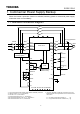
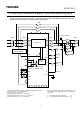
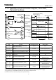
1.2. Standard connection diagram (Star-delta switching start)
This is the circuit to switch the motor to commercial power supply Star Delta (star-delta) connection
startup when the inverter’s protective function is activated.
FL
G / E
F
RES
CC
R/L1
S/L2
T/L3
U/T1
V/T2
W/T3
FLC
FLB
FLA
S1
ST
R
S2
S3
OUT2
P24/PLC
OUT1
RY2
PO
PB
PC/-
PA/+
Main circuit
MCCB
I M
RY1
MC3
*2
MC2
*3
MC1
*2
MCY
MCD
For motor protection
THR
*4
Motor
Run
command
Stand-by
*7
Reset
*6
Emergency
stop
*5
Protective action
detection
relay
Common
+SU
Control
circuit
CCA
RX
VI/II
RR/S4
PP
A
M
FM
OUT1
NO
CC
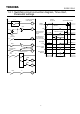
*1: The control power supply backup option (Model: CPS002Z) is needed.
*2: Observe the Item 1 in 1.3, “Precautions.”
*3: See Item 2 in 1.3, “Precautions.”
*4: Be careful about Items 3 in 1.3, “Precautions.”
*5:
Be careful about Items 5 and 7 in 1.3, “Precautions.”
*6: Be careful about Item 6 in 1.3, “Precautions.
Control power supply
backup option
*1
*7: VF-AS1's 'WP1/WN1' model and VF-PS1 don't have 'ST'
terminal. Please set next parameter for use 'S3' terminal as
'ST' function.
f110 (Always ON function selection 1) = 0
f117 (Input terminal function selection: S3) = 6