E6581738 TOSVERT VF-MB1/S15 PROFIBUS-DP Option Function Manual PDP003Z NOTICE 1. Read this manual before installing or operating. Keep this instruction manual on hand of the end user, and make use of this manual in maintenance and inspection. 2. All information contained in this manual will be changed without notice. Please contact your Toshiba distributor to confirm the latest information.
E6581738 Contents 1. Introduction ..............................................................................................................................................1 2. Connection Information............................................................................................................................6 2.1. Exterior features...........................................................................................................................6 2.2. Status indicator ............
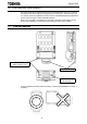
E6581738 1. Introduction Thank you for purchasing the PROFIBUS-DP option “PDP003Z” for the VF-MB1/S15. Before using the PROFIBUS-DP option, please familiarize yourself with the product and be sure to thoroughly read the instructions and precautions contained in this manual. This option needs the option adaptor to connect VF-S15 which type form is SBP009Z. Please match here and buy it when SBP009Z is not at hand yet.
E6581738 Safety precautions On the drive and in its instruction manual, important information is contained for preventing injuries to users and damages to assets and for proper use of the device. Read the instruction manual attached to VF-MB1/S15 along with this instruction manual for completely understanding the safety precautions and adhere to the contents of these manuals.
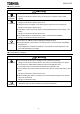
E6581738 ■ General Operation Warning ▼ Never disassemble, modify or repair. Disassembly prohibited Doing so could result in electric shock, fire and injury. For repairs, call your sales agency. ▼ Do not attach this option to any drive other than the VF- MB1/S15. Prohibited Doing so could result in electric shock or fire. ▼ When the drive is energized, never detach the this option from the VF- MB1/S15. Doing so could result in electric shock.
E6581738 ■ Wiring Warning ▼ Shut off power when installing and wiring this option. Mandatory Wait at least 15 minutes and check to make sure that the charge lamp (VF- MB1/S15) is no longer lit. ▼ Electrical construction work must be done by a qualified expert. Installation or connection of input power by someone who does not have that expert knowledge may result in fire or electric shock.
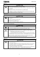
E6581738 Notes on use Notes ▼ Do not install the drive where the temperature or the humidity will change rapidly. ▼ Keep a distance of 20cm or more between the drive 's power cable and the data transmission cable. Or the drive might malfunction because of noise. ▼ Insert a magnetic contactor or similar device between the drive and the power supply to ensure that power is turned off if an emergency stop command is entered through the network.
E6581738 2. Connection Information This option allows the VF-MB1/S15 drive to be communicated with the cyclic command transmission and monitoring of the original profile ("Vendor spec.", refer to Section 4) of our company other than application profile "Profile for Variable Speed Drives PROFIdrive (3.072), refer to Section 3" which PROFIBUS defines. When you use VF-MB1, the shielding is connected to the drive ground.
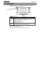
E6581738 2.2. Status indicator The PDP003Z has two LEDs, ST (status) and DX (data exchange) to indicate the statuses of PROFIBUS-DP and the PDP003Z itself. ST (status) DX (data Exchange) ST (Status): Red LED LED Meanings Off No diagnostics present 8 Hz (Blinking 4 times/1sec.): Waiting for parameterization or configuration 2 Hz (Blinking 1 times/1sec.): Flashes PDP003Z station address is "126". (Refer to 2.3 section .) DP status error Lights * For example, a station address is not setcorrectly.
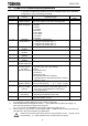
E6581738 2.3. VF-MB1/S15 Communication parameters In a network, VF-MB1/S15 (PDP003Z) serves as a PROFIBUS slave device. PDP003Z configuration is set by the following parameters. Parameter Function c150 PDP003Z Station address PDP003Z Baud rate Monitor c151 c152 PDP003Z Profile Monitor c154 JOG1 Frequency (STW.8) JOG2 Frequency (STW.9) Tmax (ZSW.8) Tolerance (ZSW.
E6581738 3. Profile 3.1. Telegram Telegram of PDP003Z is set up by the configurator. The figures below show the Telegrams and configurations that the PDP003Z supports. PKW PKE IND PZD PZD1 STW ZSW PWE PZD2 HSW HIW PZD3 PZD4 PZD5 PZD6 Telegram 1: PROFIdrive (PPO TYPE 3, 2PZD) Telegram 100: Vendor Spec. (PPO TYPE 1, 4PKW / 2PZD) Telegram 101: Vendor Spec. (PPO TYPE 2, 4PKW / 6PZD) Telegram 102: Vendor Spec.
E6581738 3.2. STW Control Word Data PDP003Z supports only speed control mode. Bit Value Name 1 ON “Switched on” condition 0 OFF Normal stop. 1 No Coast Stop 0 Coast Stop (OFF 2) 1 No Quick Stop 0 Quick Stop (OFF 3) 1 Enable Operation The drive then runs-up to the setpoint. 0 Disable Operation Normal stop.
E6581738 3.3.
E6581738 3.3.1. Tolerance Range (ZSW Bit 8) If the setpoint is changed: 1. ZSW Bit 8 is set 0 2. Calculate the tolerance. 3. Start the timer which will time-out based on parameter Tmax. PDP003Z checks that the timer (Tmax) has not timed-out and if the actual value is within the tolerance. If both conditions are fulfilled ZSW Bit 8 is set 1 and the timer is stopped. The figure shows ZSW 8 when Tolerance (c157) is 50% and Tmax (c151) is 3s.
E6581738 3.4.
E6581738 3.4.1. Examples of driving by the State Machine When using the PROFIdrive profile, the frequency reference is set to HSW. The setting value “0x0000” - ”0x4000” is equivalent to ”0” - ”Base frequency (parameter fh)”. When the reverse operation, the frequency reference is set with two's complement of the forward frequency reference. During running, HIW shows a output frequency. * fmod or cmod is set to “Communication option” on these examples. 3.4.1.1. Example 1.
E6581738 3.5. Access to the PROFIBUS parameter In the cyclic PROFIBUS-DP communication, the parameter data is transferred via Telegram 100, 101. If the requirement is not executed, the cause is distinguished by octet 7 and 8.
E6581738 3.6.
E6581738 3.6.1. Examples of reading the PROFIdrive parameter 3.6.1.1. Example 1. Reading the PNU 922 (Telegram) AK = 1 (Request parameter value) SPM = 0 PNU = 922 (0x039A) PKE 0 0 0 1 0 0 1 1 1 1 0 3 Requirement PKW PKE 13 9A 0 1 1 0 9 1 0 0 0 A PZD IND 00 00 PWE 00 Response (Value: 0x0065 = 101) 13 9A 00 00 00 00 00 00 ・・・ ・・・ 00 00 65 ・・・ ・・・ 3.6.1.2. Example 2.
E6581738 3.7. Access to VF-MB1/S15 parameter When access to VF-MB1/S15 parameter, set “1” to the PNU. The communication number of the drive parameter is set to the subindex IND. Refer to the drive instruction manual about the communication number and unit. * This procedure changes the value of VF-MB1/S15 EEPROM. 3.7.1. Examples of reading or changing VF-MB1/S15 parameter 3.7.1.1. Example 1.
E6581738 3.7.1.3. Example 3. Reading the status monitor parameter (fe02 (The operation frequency)) AK = 6 (Request parameter value (array)) SPM = 0 PNU = 1 IND = 0xFE02(fe02 communication number) PKE 0 1 1 0 0 0 6 0 0 0 0 0 Requirement PKW PKE 60 01 0 0 0 0 0 0 1 0 1 1 PZD IND FE PWE 00 00 00 ・・・ ・・・ Response (Value: 0x03E8 (= 1000 -> 10.00Hz)) 40 01 FE 02 00 00 03 E8 ・・・ ・・・ 02 00 * The status monitor parameter can not be changed. 3.7.1.4. Example 4.
E6581738 4. Vendor Spec. Profile Cyclic command transmission (the value of the parameter c001 - c006) and monitoring (the value of the parameter c021 - c026) are possible for PDP003Z by the original profile Select the ”Telegram 100”, ”Telegram 101” or ”Telegram 102” as the profile on the configuration. Refer to the PLC configurator documents. c001 - c006 setup value c021 - c026 setup value 0: No action 1: fa06 (Communication command 1) 2: fa23 (Communication command 2) 3: fa07 (Fequency command, 0.
E6581738 4.1. How to use The purposes are adjustment by real time command transmission, and the monitor of an operation state by using cyclic communication of PROFIBUS. Example 1: Command transmitting When you want to set "0xC400" to parameter fa06, set “1 (fa06)” to parameter c001. And Since 0 and 1 byte of the PZD1 supports the parameter c001, if "0xC400" is set up here, "0xC400" will be set as fa06. VF-MB1 PDP003Z Parameter c001 c002 c003 ... Value 1 (FA06) ... ... ...
E6581738 4.2. The overview of the VF-MB1/S15 parameter Refer to a communication functional description (E6581726/E6581913) for details. 4.2.1.
E6581738 4.2.2. fa23 (Communication command 2) bit 0 1 2 3 4 5 6 7 8 Function (Reserved) Electric power quantity reset (Reserved) (Reserved) (Reserved) (Reserved) (Reserved) Maximum deceleration forced stop Acceleration/deceleration selection 1 10 11 Acceleration/deceleration selection 2 (Reserved) (Reserved) 12 OC stall level switch 9 13 (Reserved) 14 (Reserved) 15 (Reserved) Note: Set 0 to reserved bit.
E6581738 4.2.3. fa07 (frequency reference from internal option) Frequency reference is set up by 0.01Hz unit and the hexadecimal number. For example, when "Frequency reference" is set up to 80Hz, since the minimum unit is 0.01Hz, 80 / 0.01 = 8000 = 0x1F40 (Hex.) 4.2.4. fa50 (Terminal output data from communication) By setting up the data of the bit 0 - 1 of terminal output data (fa50) from communication, setting data (OFF or ON) can be outputted to the output terminal.
E6581738 4.2.6. fd01 (Inverter operating status 1 (real time)) bit 0 Function Failure FL 0 No output 1 Under in progress Note - Trip status includes rtry and the trip retention status are also regarded as tripped statuses.
E6581738 4.2.8. fd03 (Output current (real time)) The output current is read into 0.01% of units and by the hexadecimal number. For example, when the output current of the rated current 4.8A drive is 50% (2.4A), 0x1388 (hexadecimal number) is read out. Since the minimum unit is 0.01%, 0x1388 (Hex.) = 5000 (Dec.) * 0.01 = 50 (%) Also about the following parameters, these are the same as this. - fd05 (Output voltage (real time)) ............................................. Unit: 0.
E6581738 4.2.12. bit fc91 (Alarm code) Function 0 1 Remarks (Code displayed on the panel) Alarming Alarming Alarming Alarming Alarming Alarming Alarming Alarming Alarming Alarming Alarming Alarming Alarming Alarming Dec., Under stop Dec.
E6581738 4.2.14. fd07 (Output TB Status) bit TB Name Function (Parameter) 0 0 RY-RC Output terminal function selection 1A (f130) OFF 1 OUT Output TB Function select 2A (f131) OFF 2 FL Output TB Function select 3 (f132) OFF 3 - 15 (Undefined) Note: The bit described "Undefined" is unstable. Do not use the bit for the judgment.
E6581738 5. Diagnostic When the communication loss occurs, PDP003Z returns the diagnosis telegram including the following information.
E6581738 6. DP-V1 function DP-V1 acyclic communication is mainly used to read/write the parameter. VF-MB1/S15 parameter and the PROFIBUS parameter can be read/written using PDP003Z. The following setting is necessary in the configuration to communicate DP-V1. (The figure below is a setting for SIMATEC Step7.) Parameter access sequence to VF-MB1/S15 takes place as described in the following figure.
E6581738 6.1. Example1. Read the PROFIdrive parameter 6.1.1. Write Request data table (Read PNU 964 (0x03C4) IND 4) Field Header DU0 Header DU1 Header DU2 Header DU3 Request Header (Byte 1) Request Header (Byte 2) Request Header (Byte 3) Request Header (Byte 4) Parameter Address (Byte 1) Parameter Address (Byte 2) Parameter Address (Byte 3) Parameter Address (Byte 4) Parameter Address (Byte 5) Parameter Address (Byte 6) 6.1.2.
E6581738 6.2. Example 2. Change the PROFIdrive parameter 6.2.1.
E6581738 6.3. Example 3. Read the VF-MB1/S15 parameter When access to VF-MB1/S15 parameter, set “1000” to the PNU. 6.3.1.
E6581738 6.4. Example 4. Change the VF-MB1/S15 parameter When access to VF-MB1/S15 parameter, set “1000” to the PNU. * This procedure changes the value of VF-MB1/S15 EEPROM. 6.4.1.
E6581738 7. PROFIBUS Local/Remote Operation The example below shows how to configure the VF-MB1 for local/remote operation. F terminal ............ RUN command R terminal............ Local (Terminal in this example) / PROFIBUS switching VIA terminal ........
E6581738 9.