INTRODUCTION4 INTRODUCTION PREPARATION11 PREPARATION Instruction Manual PLAYBACK OPERATION OPERATION39 RECORDING OPERATION OPERATION23 VIRTUAL REAL-TIME & TIME LAPSE VCR KV-9168A PAUSE/STILL TIME LAPSE VCR POWER PLAY STOP REV FWD 4Head 168Hour TAPE REMAIN DISPLAY – TIME MODE + SET COUNTER MEMORY ALARM SHIFT RESET TRACKING LOCATION SELECT NOTICE NOTICE 44 HIGH DENSITY
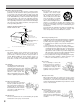
INTRODUCTION PLEASE READ The lightning flash with arrowhead symbol, within an equilateral triangle, is intended to alert the user to the presence of uninsulated “dangerous voltage” within the product’s enclosure that may be of sufficient magnitude to constitute a risk of electric shock to persons. WARNING RISK OF ELECTRIC SHOCK DO NOT OPEN. PREPARATION WARNING: TO REDUCE THE RISK OF ELECTRIC SHOCK, DO NOT REMOVE COVER (OR BACK). NO USERSERVICEABLE PARTS INSIDE.
INTRODUCTION IMPORTANT SAFETY INSTRUCTIONS CAUTION: PLEASE READ AND OBSERVE ALL WARNINGS AND INSTRUCTIONS GIVEN IN THIS OWNER’S MANUAL AND THOSE MARKED ON THE UNIT. RETAIN THIS BOOKLET FOR FUTURE REFERENCE. This set has been designed and manufactured to assure personal safety. Improper use can result in electric shock or fire hazard. The safeguards incorporated in this unit will protect you if you observe the following procedures for installation, use and servicing.
INTRODUCTION 10. Outdoor Antenna Grounding If an outside antenna or cable system is connected to the product, be sure the antenna or cable system is grounded so as to provide some protection against voltage surges and built-up static charges.
INTRODUCTION INTRODUCTION FEATURES i i i i i i i Internal time-date generator. This VCR includes an internal time-date generator, necessary for documentation purposes. (See page 15.) i i On-screen programming. Menu driven programming simplifies set-up of various functions including but not limited to the following: time & date search, timer setting, and alarm recording. Timer recording function.
INTRODUCTION INSTRUCTIONS IN BRIEF Front Panel 2 3 4 REC REC CHECK TIMER 6 7 12 13 14 16 18 19 21 22 VIDEO MODE AUTO COLOR B/W PAUSE/STILL REMOTE EJECT POWER OFF REMOTE OPTION TIME LAPSE VCR BUZZER PREPARATION ON TAPE REMAIN SOFT RECORDING OPERATION REV FWD 1 2 3 5 6 23 5 DISPLAY 8 9 ALARM SHIFT + 10 11 TRACKING LOCATION SELECT RESET VCR DISPLAY REC CHECK button Press this button while in record mode to check the picture that was just recorded.
y u ; DISPLAY button Press to display the MENU screen and change the settings. a SHIFT / button Press to select a desired menu on the screen. s TIME MODE / SET + – buttons • Press either of the buttons to set the recording time mode and playback time mode. • Press either the + or the – button to set the mode and the numerical value for each menu on the screen. INTRODUCTION CASSETTE COMPARTMENT Insert a cassette into this compartment to load the tape. PLAY button Press to start the playback mode.
INTRODUCTION Rear Panel OPTION BOX cover 4 5 6 7 9 10 BATTERY cover ALL CLEAR REMOTE IN ALARM IN GND RESET IN PREPARATION OUT GND SEE MANUAL 3 RECORDING OPERATION IN VIDEO OUT IN AUDIO OUT 13 1 8 11 SEE MANUAL 12 2 2 3 4 PLAYBACK OPERATION MIC IN TAPE END 1 5 6 7 NOTICE REC EXT TRIGG. CONT. OUT GND 8 9 7 TAPE END OUT terminal Signal output terminal to annunciate to other devices that the tape has run out on the VCR.
i The nickel-cadmium battery pack (3N-100AAS) is used for power source of the built-in clock and memory circuit. i Charging the Battery Pack 1. Turn on the power of the VCR. 2. The battery pack in the VCR is charged. Battery Installation Removal: 1. Remove the battery cover. 2. Disconnect the connector in the VCR.
INTRODUCTION VCR DISPLAY 2 3 4 1 COUNT. M RECORDING OPERATION PREPARATION PLAY 5 6 PLAYBACK OPERATION NOTICE DEW SP TIMER EP H PW.FAIL 10 Cassette indicator Lights when a tape is inserted. Counter memory indicator Lights when the counter memory is selected. Alarm Memory indicator Lights when the alarm memory is selected. Alarm indicator Lights during alarm recording and blinks after an alarm recording cycle is completed. PW.FAIL (Power Failure) indicator Blinks when a power failure occurs.
2 PLAY PICTURE SEARCH REW (±) PLAY FF TIME (+) 3 4 5 3 4 5 INTRODUCTION STOP button Press to stop tape running. PLAY button Press to start play back. FF button • Press to fast forward mode. • Press during playback for forward picture search mode. To release the forward picture search mode, press the PLAY button. • Press the FF button while pressing the PLAY button, the Time mode can be selected.
INTRODUCTION PREPARATION CONNECTIONS Connection with a Video Camera Monitor TV To VIDEO IN (BNC connector) PREPARATION To VIDEO OUT (BNC connector) RG/59u coaxial cable. camera To AC OUTLET (120V) To VIDEO IN (BNC connector) To VIDEO OUT (BNC connector) ALL CLEAR REMOTE IN ALARM IN GND RESET IN OUT GND REC EXT TRIGG. CONT.
INTRODUCTION Typical Connection with the Sequential Switcher When connected with a sequential switcher, set the alarm recording mode to MANUAL by menu screen. For further details, consult the instruction manuals of the connected devices. ALL CLEAR REMOTE IN ALARM IN IN OUT GND REC EXT TRIGG. CONT. OUT GND MIC IN IN VIDEO OUT IN AUDIO OUT TAPE END SEE MANUAL To VIDEO IN SEE MANUAL To VIDEO OUT To REC TRIGG.
INTRODUCTION CONTENTS OF SCREEN DISPLAY The normal MENU screen provides six menus after the initial screen for clock setting. Each MENU screen is shown below. Press the DISPLAY button for a MENU screen. The menu is selected by pressing the SHIFT button. Then press the SET button to proceed to the next screen. Use the SHIFT button and the SET button for settings and adjustments in the same manner. To return to the initial screen press the DISPLAY button.
END=[DISPLAY] ALARM RECALL Screen M E N U CLOCK ADJUST SETUP DISPLAY MODE PROGRAM ALARM RECALL TIME DATE SEARCH END=[DISPLAY] AL1 AL2 AL3 AL4 AL5 AL6 AL7 1ST ALARM RECALL --/--/----- --:--:---/--/----- --:--:---/--/----- --:--:---/--/----- --:--:---/--/----- --:--:---/--/----- --:--:---/--/----- --:--:---/--/----- --:--:-MENU=[DISPLAY] TIME DATE SEARCH Screen M E N U CLOCK ADJUST SETUP DISPLAY MODE PROGRAM ALARM RECALL TIME DATE SEARCH END=[DISPLAY] TIME DATE SEARCH DAY HOUR MINUTE 01 00 00 SEARCH F
INTRODUCTION SETTING THE CLOCK An internal clock generates time and date for superimposing on the monitor screen. Adjust the time from the MENU screen (initial screen). After the clock is set, the data and time modes are displayed on the monitor screen (live picture). Operation PREPARATION In case of setting to 5:30 PM, Thursday, August 28, 1997; 1 Press the DISPLAY button.
When the power is turned ON, the time and date modes are displayed on the monitor screen (live picture). On-screen displays are not available in the event of no video input signal. INTRODUCTION ON-SCREEN FUNCTIONS Date-Time Display VCR display 8/28/97 THU 17:30:02 SPA 2 3 Time Monitor screen SP : SP mode Nothing : EP mode On-Screen Position 8/28/97 THU 17:30:02 SPA 2 Press the LOCATION SELECT button to adjust the display to desirable position. The display moves in the direction shown by the arrows.
INTRODUCTION DISPLAY SCREEN Set the MENU screen to DISPLAY screen, and select or set each item. Before operation, set the MENU screen to DISPLAY screen (See page 13.). Note: Press the DISPLAY button twice to return from the display screen to the monitor screen. PREPARATION Operation Erasing the date display. Press the or SHIFT button to blink DATE and press the + or – SET button to go to OFF.
DISPLAY – TIME MODE + SET TRACKING SHIFT LOCATION SELECT Changes as shown below each time the SET button is pressed. OFF → V01 → V02 → V03 → V04 → V05 → V06 → V07 → V08 → OFF DISPLAY (DATE) ON (DAY OF THE WEEK) ON (TIME) ON (SPEED) ON (VCR) V01 (ALARM) ON (12H/24H) 24H (CHAR.LINES) 6 MENU=[DISPLAY] VCR number 8/28/97 THU 17:30:02 SPA 2 V01 Displaying the number of alarms. Press the or SHIFT button to blink ALARM and press the + or – SET button to go to ON.
INTRODUCTION PREPARATION COUNTER DISPLAYS Counter Memory When the counter is set to “0000” at a location that you want to see again during recording and playback, the tape will stop in the vicinity of “0000” during rewind and fast forward. 1 When the alarm counter is displayed, press the ALARM button to set the display to the counter display. ALARM REC 3 Press the COUNTER MEMORY button to make “COUNT.M” (Counter Memory) to light. REC COUNTER MEMORY 2 ALARM H COUNT.
In the cases shown below, Alarm Memory search may be not carried out. i If the alarm recording is not carried out for more than those listed in the following chart then, the alarm may be skipped. i If the alarm recording interval is not left for more than those listed in the following chart then, the alarm may be skipped. i If there is not enough time between the beginning of the alarm search and the first alarm activation.
INTRODUCTION SETTING THE RECORDING/PLAYBACK TIME i Before performing playback/recording, it is necessary to set the desired time mode.
INTRODUCTION LOADING AND UNLOADING A VIDEO CASSETTE Cassette compartment REC REC CHECK TIMER VIDEO MODE AUTO COLOR B/W PAUSE/STILL REMOTE EJECT POWER 1 2 OFF REMOTE OPTION TIME LAPSE VCR BUZZER 4Head 168Hour ON OFF PLAY STOP REV FWD TAPE REMAIN DISPLAY COUNTER MEMORY ALARM RESET + TRACKING LOCATION SELECT Unloading a Cassette 1 Turn the power ON. 2 Press the EJECT button.
INTRODUCTION RECORDING OPERATION RECORDING 1 Turn on the power for this VCR as well as associated devices of the surveillance system including the video camera and monitor TV. 5 Insert a video cassette to this VCR. • Check that the safety tab on the video cassette has not been removed.
INTRODUCTION RESTART RECORDING Setting the Restart Recording On the SETUP screen set RESTART REC to ON. – TIME MODE + SET TRACKING SHIFT LOCATION SELECT Press the or SHIFT button to blink SETUP and press the + or – SET button. 2 DISPLAY – TIME MODE + SET LOCATION SELECT Press the or SHIFT button to blink RESTART REC. DISPLAY – TIME MODE + SET TRACKING SHIFT LOCATION SELECT Press the + or – SET button to go to ON.
INTRODUCTION TIMER RECORDING There are two kinds of timer recording. One is daily timer recording, and the other is weekly timer recording. Once the timer programs are set, the VCR can retain all programmed information in the event of a power failure (10 day maximum memory storage). Before setting timer programs, make sure that the present time is correct. (See page 15 ~ 16.
DISPLAY – TIME MODE + SET TRACKING SHIFT LOCATION SELECT FR1 FR2 SA1 SA2 SU1 SU2 DLY EXT FR1 FR2 SA1 SA2 SU1 SU2 DLY EXT ON ON ON ON ON ON ON ON ON ON ON ON ON ON ON ON SP 120 SP 120 SP 120 SP 120 SP 120 SP 120 i SP 120 The TIME MODE button is pressed, the display changes as follows. SP120 → 120 → SP168 → 168 → SPL01 → SPL02 → SPL03 → SPA2 → A6 → SPA12 → A18 → SPA24 → SP24 → 30 → SP48 → 48 → SP72 → 72 → SP120 The TIME MODE button is pressed, the display changes in the reverse direction.
INTRODUCTION Weekly Timer Recording To record every week for certain period on a certain day of the week, set the weekly timer recording. With the weekly timer recording, 2 programs are possible for each day of the week. In case of setting EPA18 from 8:00 to 19:00 on all weekdays, and EPA18 from 9:00 to 17:00 on Saturday and Sunday. PREPARATION 1 Press the DISPLAY button.
DISPLAY – TIME MODE + SET TRACKING SHIFT ON ON ON ON ON ON ON ON LOCATION SELECT 10 Press the SHIFT button twice to blink the TU1 start time. Repeat steps from 5 to 9.
INTRODUCTION ALARM RECORDING If an alarm condition arises, the alarm function operates with an alarm input signal. Operation at Alarm Input When there is an alarm during recording, recording pause or stop modes, the VCR automatically goes into alarm recording mode. The VCR can be programmed to record in the following time modes during alarm recording: SPA2, EPA6, SPA12, EPA18, SPA24.
INTRODUCTION Connecting the Alarm Terminals i Connecting the ALARM IN/OUT terminals Alarm switch To GND External interface To alarm out Alarm lamp or alarm buzzer • When the alarm switch is ON, alarm recording starts. It is possible to confirm the warning from outside by connecting the switching input of external interface devices such as alarm lamp or alarm buzzer to the alarm output. Please do not use the alarm output for power source to any of external devices.
INTRODUCTION PREPARATION Setting the Alarm Recording 1 Press the DISPLAY button. DISPLAY – TIME MODE M E N U CLOCK ADJUST SETUP DISPLAY MODE PROGRAM ALARM RECALL TIME DATE SEARCH + SET TRACKING SHIFT S E T U P DISPLAY – TIME MODE + SET END=[DISPLAY] LOCATION SELECT TRACKING SHIFT ALARM REC TIME SPEED RESTART REC TAPE END MODE ALARM 15S 2 OFF STOP STOP SP A LOCATION SELECT 2 Press the SHIFT button to blink SETUP and press the + SET button.
Auto Recording is convenient when it is necessary to activate recording with a trigger input while the unit is in either timer record or timer standby mode. When there is a trigger input to the External Control terminal on the rear side, the unit will begin recording in the previously programmed record mode. INTRODUCTION AUTO RECORDING Connecting the External control terminal PREPARATION Auto recording To external control To GND Operation of Auto Recording 1 Press the DISPLAY button.
INTRODUCTION Press the + or – SET button to set the auto recording time mode. 5 DISPLAY – TIME MODE + SET TRACKING PREPARATION SHIFT FR1 FR2 SA1 SA2 SU1 SU2 DLY EXT ON ON ON ON ON ON ON ON PROGRAM --:-- ➜ --:---:-- ➜ --:---:-- ➜ --:---:-- ➜ --:---:-- ➜ --:---:-- ➜ --:---:-- ➜ --:-- LOCATION SELECT 6 SP 120 SP 120 SP 120 DISPLAY – 8 Turn on the auto recording switch on . While switch is on, recording is available.
The VCR can be programmed to respond differently when the tape reaches its end. The following describes how to set the different modes of operation.
INTRODUCTION The VCR can be programmed to automatically rewind the tape when the tape reaches its end. How to Set to Auto Rewind at End of Tape Press the DISPLAY button. 1 DISPLAY – TIME MODE + PREPARATION SET TRACKING SHIFT LOCATION SELECT Press the or SHIFT button to blink SETUP and press the + SET button. 2 DISPLAY – TIME MODE + SET RECORDING OPERATION LOCATION SELECT Press the or SHIFT button to blink TAPE END MODE.
How to Set to Repeat Record at End of Tape + SET TRACKING SHIFT LOCATION SELECT – TIME MODE + SET TRACKING SHIFT LOCATION SELECT i Now the Repeat Recording END=[DISPLAY] ALARM REC TIME 15S SP A 2 SPEED RESTART REC OFF TAPE END MODE REW ➜REC ALARM STOP MENU=[DISPLAY] Setting is completed. 2 Press the or SHIFT button to blink SETUP and press the + SET button. DISPLAY – TIME MODE + SET TRACKING SHIFT Press the or SHIFT button to blink TAPE END MODE.
INTRODUCTION RECORDING WITH THE SEQUENTIAL SWITCHER This VCR can work with a sequential switcher connected for recording. Connection with the Sequential Switcher PREPARATION For detailed operations and connections of the switcher, consult the Instruction Manual of the sequential switcher. Sequential switcher To REC trigg.
INTRODUCTION REC Trigger Output Selection in the Alarm Recording REC Trigger output can be selected during the alarm recording. DISPLAY – TIME MODE 4 M E N U CLOCK ADJUST SETUP DISPLAY MODE PROGRAM ALARM RECALL TIME DATE SEARCH + SET Press the SHIFT button. And press the + SET button to set the REC trigger SEL. DISPLAY – TIME MODE TRACKING SHIFT S E T U P + REC TRIGGER SEL.
INTRODUCTION PLAYBACK OPERATION PLAYBACK 1 Turn the power ON for the monitor TV. 3 Press the PLAY button. PREPARATION PLAY 1 2 2 3 Insert a tape which has been recorded on. REC REC CHECK TIMER STOP 4 VIDEO MODE AUTO COLOR B/W Select the playback time mode.
INTRODUCTION Using the SHUTTLE Dial CENTER 2nd Step 1st Step 2nd Step PREPARATION 1st Step rse Rev e Fo rw n io tion ec dir STOP ct d ar dir e You can also activate the picture search and slow playback of various speed by turning the shuttle dial on the VCR.
INTRODUCTION PREPARATION PLAYBACK IN VARIOUS MODES The following operations are possible during playback. Picture Search Still Playback It is possible to carry out fast forward and rewind while viewing picture and thus quickly locate the section you wish to view (image played back at speed of 5 times faster than SPA2 mode). Turn the SHUTTLE dial all the way to the left or right during playback. (See page 40.
Searching a picture at a desired day and time is possible by specifying the day and hour on the MENU screen. The VCR automatically records the current date and time (day/hour/minute). Accordingly, make sure before recording that the date and time is exactly adjusted.
INTRODUCTION ALARM SEARCH With the alarm search function, it is possible to search for alarm that has been recorded on the tape. PREPARATION Search Operation 1 Press the STOP button. ALARM REC PLAY 2 3 H Turn the SHUTTLE dial to set rewind or fast forward. ALARM M PLAY ALARM H SP SP STOP REV Press the COUNTER MEMORY button twice to make “ALARM M” to light. ALARM M ALARM 4 FWD When the tape reaches the alarm recorded position, The VCR automatically enters the still picture mode.
INTRODUCTION NOTICE SIGNAL LEVELS OF INPUT/OUTPUT TERMINALS Signal level Input/Output Terminal Additional remarks Open Ground input 0V ± 0.5V 100 IN GND 200 ms or greater 0.001µ 10K Open DC5V Ground input 0V ± 0.5V 100 RESET GND 0.001µ 200 ms or greater Alarm recording 220 OUT 10 GND Output impedance 230 Ohm : MAX 10mA 0V 10K DC5V 5V output ALARM OUT REC TRIGG.
INTRODUCTION DAILY AND PERIODIC INSPECTION This VCR has been designed to stand the use over long periods. Nevertheless, we recommend you to carry out regular daily inspection to insure problem-free use. Note: It is particularly important to carry out daily checks when using the VCR for repeat recording. PREPARATION Order of Daily Checks 1 Turn the power ON for this VCR and for the connected devices in the surveillance system including the video camera and monitor TV. 6 Press the PLAY button.
If an abnormality is found, turn the power switch to OFF and remove the power plug from the household AC outlet. Then consult with your dealer. INTRODUCTION Steps to Take after Daily Checks Total time: Time since the last maintenance: i 1 Max. 99999 hours (approximate value) Max. 9999 hours (approximate value) Regularly clean and replace parts in this VCR using the displayed usage times as a guide. For further details, consult your dealer. Press the DISPLAY button.
INTRODUCTION CAUTIONS DURING USE Dew Condensation This VCR includes a safety function to prevent operation when dew condensation occurs and thus protects against damage to tapes, the video heads and other parts.
Power does not go ON. There is no camera picture. i Is the power plug securely inserted to an AC outlet? i Is the VCR properly connected to the TV, video camera and other The camera picture is indistinct. devices? i Is there any problem with the connection of the connecting cords? i Is the camera properly focused? Function/Operation The VCR does not operate even when the control buttons are pressed. The clock does not run after restoration of power following a power failure. The buzzer does not sound.
There is excessive noise in the playback picture. The playback picture is not clear. The time-lapse mode playback picture or still playback shakes up and down. Two recorded sections appear in the playback picture when using several video cameras and changing cameras. When the VCR power plug is inserted to the AC outlet, recording starts and playback is not possible. PREPARATION INTRODUCTION Playback i Adjust with the TRACKING button. i The video head may be clogged or worn out. Consult with your dealer.
Audio input Audio output No. of audio tracks Audio frequency characteristics Audio S/N Operating conditions Storage conditions Connector section Alarm input Alarm reset input Alarm output Recording trigger output Tape end output External control input Ground input: 0 to 0.5V Ground input: 0 to 0.
LIMITED WARRANTY INTRODUCTION TIME LAPSE VIDEO CASSETTE RECORDER The Imaging Systems Division of Toshiba America Information Systems, Inc. (“ISD”) makes the following limited warranties with regard to this Time Lapse Video Cassette Recorder (“Product”). These limited warranties extend to the Original End-User (“You[r]”).