E6581090 Safety precautions I Contents Read first Industrial Inverter (For three-phase inductive motors) Connection Simple operation Basic VF-nC1 operations Instruction Manual Industrial Inverter Basic parameters Extended parameters Variety of operation Ultra-Compact, Easy-To-Use Inverter TM TOSVERT VF-nC1 TOSVERT VF-nC1 Monitoring the operation status Taking measures to satisfy the CE / UL / CSA Peripheral devices Table of parameters and data Specifications Before making a service call - Trip
E6581090 I. I Safety precautions The items described in these instructions and on the inverter itself are very important so that you can use the inverter safely prevent injury to yourself and other people around you as well as prevent damage to property in the area. Thoroughly familiarize yourself with the symbols and indications shown below and then continue to read the manual. Make sure that you observe all warnings given.
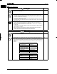
E6581090 I ■General operation Danger See item • Never disassemble, modify or repair. This can result in electric shock, fire and injury. For repairs, call your sales agency. 2. • Never remove the front cover when power is on or open door if enclosed in a cabinet. The unit contains many high voltage parts and contact with them will result in electric shock. • Don't stick your fingers into openings such as cable wiring hole and cooling fan covers. This can result in electric shock or other injury.
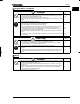
E6581090 I ■Transportation Installation Danger Prohibited Mandatory • Do not install or operate the inverter if it is damaged or any component is missing. This can result in electric shock or fire. Please consult your local sales agency for repairs. • Do not place any inflammable objects nearby. If a flame is emitted due to malfunction, it may result in a fire. • Do not install in any location where the inverter could come into contact with water or other fluids.
E6581090 I Danger Mandatory • Electrical construction work must be done by a qualified expert. Connection of input power by someone who does not have that expert knowledge may result in fire or electric shock. • Connect output terminals (motor side) correctly. If the phase sequence is incorrect, the motor will operate in reverse and that may result in injury. • Wiring must be done after installation. If wiring is done prior to installation that may result in injury or electric shock.
E6581090 Warning • Observe all permissible operating ranges of motors and mechanical equipment. (Refer to the motor's instruction manual.) Not observing these ranges may result in injury. See item 3. Prohibited When sequence for restart after a momentary power failure is selected (inverter) Warning Mandatory • Stand clear of motors and mechanical equipment If the motor stops due to a momentary power failure, the equipment will start suddenly after power recovers.
E6581090 I Attach warning labels Shown here are examples of warning labels to prevent, in advance, accidents in relation to inverters, motors and other equipment. If the inverter has been programmed for auto-restart function after momentary power failure or retry function, place warning labels in a place where they can be easily seen and read.
E6581090 ― Contents ― I. Safety precautions・・・・・・・・・・・・・・・・・・・・・・・・・・・・・・・・・・・・・・・・・・・・・・・・・・・・・・・・・・・・・・・・・ 1 1.1 1.2 1.3 1.
E6581090 8.2 Display of trip information ・・・・・・・・・・・・・・・・・・・・・・・・・・・・・・・・・・・・・・・・・・・・・・・・・・・・・・・ 9.1 9.2 Taking measures to satisfy the CE / UL / CSA ・・・・・・・・・・・・・・・・・・・・・・・・・・・・・・・・・・・・・・・・・ Compliance with the CE Marking・・・・・・・・・・・・・・・・・・・・・・・・・・・・・・・・・・・・・・・・・・・・・・・・・ Compliance with UL Standard and CSA Standard ・・・・・・・・・・・・・・・・・・・・・・・・・・・・・・・・・・ I-1 I-1 I-6 10. Peripheral devices・・・・・・・・・・・・・・・・・・・・・・・・・・・・・・・・・・・・・・・・・・・・・・・・・・・・・・・・・・・・・・・・・ 10.
E6581090 1. Read first 1.1 Check purchased product 1 Before using the product you have purchased, check to make sure that it is exactly what you ordered. Warning Use an inverter that conforms to the specifications of power supply and threephase induction motor being used. If the inverter being used does not conform to Mandatory those specifications, not only will the three-phase induction motor not rotate correctly, but it may cause serious accidents through overheating and fire.
E6581090 1.3 Name and function of each part 1.3.1 1 Operation keypad panel Monitor key Switches among operation, setting and status monitor modes. RUN lamp Input main circuit terminal block Used to connect a power source. PRG lamp Blinks while the inverter is in operation. RUN key Pressing this key while the RUN key lamp is lighted starts operations. Lights when the inverter is in parameter setting mode.
E6581090 [Front panel] Charge lamp Indicates that high voltage is still present within the inverter. Do not open the terminal board cover while this is lit. This lamp is not provided for single-phase 200V European models. Front cover Connector for optional devices Control terminal block Used to connect an optional device. • Parameter writer • Extension panel • RS485/RS232C Used to control the inverter by inputting signals from an external control device and to output signals to the external device.
E6581090 Caution label on the top surface (See Note 1.) Main circuit port Control circuit port 1 Ventilation slits Name Plate [Bottom] [Right side] Note 1: When installing the inverter where the ambient temperature will rise above 40°C, detach this caution label.
E6581090 Note: The self-up (self-lifting) terminals of VFNC1 are constructed with plastic body and screws, therefore please take following precautions. • Do not unscrew the power terminals to UP position frequently. (Less than 5 times is recommended) • Do not press the screw when unscrew the main terminals. • Do not unscrew quickly like using an Electric screw driver. • Do not pull the power wire during unscrewing the power terminals to UP position.
E6581090 VFNC1-2015P~2022P [Main circuit input terminals] 1 [Main circuit output terminals] VFNC1S-1001P~1004P VFNC1S-2002P~2007P [Main circuit input terminals] [Main circuit output terminals] A-6
E6581090 VFNC1S-1007P VFNC1S-2015P~2022P [Main circuit input terminals] 1 [Main circuit output terminals] VFNC1S-2002PL~2007PL [Main circuit input terminals] [Main circuit output terminals] A-7
E6581090 VFNC1S-2015PL~2022PL [Main circuit input terminals] 1 [Main circuit output terminals] 2) Control circuit terminal block The same type of terminal board is provided for all models. Sizes of connectable wires Solid wire: 0.3 to 1.5 (mm2) Stranded wire: 0.3 to 1.5 (mm2) (AWG: 22 to 16) Sheath strip length: 6 mm Driver bit size: 3.5 × 0.6 mm Sizes of connectable wires Solid wire: 0.3 to 1.5 (mm2) Stranded wire: 0.3 to 1.25 (mm2) (AWG: 22 to 16) Sheath strip length: 5 mm Driver bit size: 2.5 × 0.
E6581090 1.4 1.4.1 Notes on the application Motors When the VF-nC1 and the motor are used in conjunction, pay attention to the following items. Warning Use an inverter that conforms to the specifications of the three-phase induction motor and power supply being used. If the inverter being used does not conform to those Mandatory specifications, not only will the three-phase induction motor not rotate correctly, but it may causes serious accidents through overheating and fire.
E6581090 Loads that generate negative torque When combined with loads that generate negative torque the protection for overvoltage and overcurrent on the inverter will go into operation and may cause a trip. For this kind of situation, you must install a dynamic braking resistor, etc. that complies with the load conditions. 1 Motor with brake If a motor with brake is connected directly to the output side of the inverter, the brake will not release because voltage at startup is low.
E6581090 Circuit interrupting when two or more inverters are used on the same power line. (circuit MCCB2 interrupting fuse) MCCB1 INV1 MCCB3 1 INV2 MCCBn+1 INVn Breaking of selected inverter There is no fuse in the inverter's main circuit. Thus, as the diagram above shows, when more than one inverter is used on the same power line, you must select interupting characteristics so that only the MCCB2 will trip and the MCCB1 will not trip when a short occurs in the inverter (INV1).
E6581090 Remedies: 1. 2. 1 3. Reduce PWM carrier frequency. The setting of PWM carrier frequency is done with the parameter H . Use high frequency remedial products for earth leakage breakers. If you use equipment like this, there is no need to reduce the PWM carrier frequency.
E6581090 1.4.4 Installation ■Installation environment The VF-nC1 Inverter is an electronic control instrument. Take full consideration to installing it in the proper operating environment. Danger • Do not place any inflammable substances near the VF-nC1 Inverter. If an accident occurs in which flame is emitted, this could lead to fire. Prohibited • Operate under the environmental conditions prescribed in the instruction manual. Operations under any other conditions may result in malfunction.
E6581090 • Operate in areas where ambient temperature ranges from -10°C to 50°C. However, when installing the inverter where the ambient temperature will rise above 40°C, detach the caution label on the top surface. 1 5cm 5cm 5cm Measurement position Measurement position Note: The inverter is a heat-emitting body. Make sure to provide proper space and ventilation when installing in the cabinet.
E6581090 ■How to install Danger Prohibited • Do not install and operate the inverter if it is damaged or any component is missing. This can result in electric shock or fire. Please consult your local agency for repairs. • Must be installed in nonflammables such as metals. The rear panel gets very hot so that if installation is in an inflammable object, this can result in fire. Mandatory • Do not operate with the front panel cover removed. This can result in electric shock.
E6581090 ■Calorific values of the inverter and the required ventilation 1 The energy loss when the inverter converts power from AC to DC and then back to AC is about 5-10 percent. In order to suppress the rise in temperature inside the cabinet when this loss becomes heat loss, the interior of the cabinet must be ventilated and cooled. Operating motor Voltage Class capacity (kW) Single-Phase 100V Class Single-Phase 200V Class Three-Phase 200V Class 0.1 0.2 0.4 0.75 0.2 0.4 0.75 1.5 2.2 0.1 0.2 0.4 0.
E6581090 ■Installing more than one unit in a cabinet If you are installing two or more inverters in one cabinet, pay attention to the following. • Inverters may be installed side by side with each other with no space left between them. When installing inverters side by side, detach the caution label on the top surface of each inverter and use them where the ambient temperature will not rise above 40°C.
E6581090 2. Connection Danger • Never disassemble, modify or repair. This can result in electric shock, fire and injury. For repairs, call your sales agency. Disassembly prohibited • Don’t stick your fingers into openings such as cable wiring hole and cooling fan covers. This can result in electric shock or other injury. • Don't place or insert any kind of object into the inverter (electrical wire cuttings, Prohibited rods, wires). This can result in electric shock or fire.
E6581090 Warning Prohibited 2 • Do not attach devices with built-in capacitors (such as noise filters or surge absorber) to the output (motor side) terminal. This could cause a fire. ■Preventing radio noise To prevent electrical interference such as radio noise, separately bundle wires to the main circuit's power terminals (R/L1, S/L2, T/L3) and wires to the motor terminals (U/T1, V/T2, W/T3).
E6581090 2.2.1 Standard connection diagram (1) This diagram shows a standard wiring of the main circuit.
E6581090 ■When using V1/S3 terminal as a logic input terminal (H : ) *6 DC reactor (DCL: option) 2 P0 *5 MCCB R/L1 PA PC *1 U/T1 Main circuit S/L2 W/T3 FLC Fault output signal IM V/T2 T/L3 Control circuit FLB FLA F Forward R Reverse VF-nC1 S1 Preset speed 1 S2 Preset speed 2 Connector for optional devices CC Common P15 *4 VI/S3 *2 *3 FM/OUT*2 CC CC Preset speed 3 + Frequency meter (Ammeter) Meter Ry - 1-phase series MCCB Power supply R/L1 S/L2 1-phase series d
E6581090 2.2.
E6581090 ■When using V1/S3 terminal as a logic input terminal (H : ) *5 DC reactor (DCL: option) 2 P0 *4 MCCB R/L1 PA PC *1 U/T1 Main circuit S/L2 W/T3 FLC Fault output signal IM V/T2 T/L3 Control circuit FLB FLA VF-nC1 Connector for optional devices F Forward R Reverse S1 Preset speed 1 S2 Preset speed 2 P15 VI/S3 *2 *3 FM/OUT*2 CC Common Preset speed 3 + Frequency meter (Ammeter) Meter Ry - 1-phase series Power supply R/L1 S/L2 1-phase series do not have T/L3 t
E6581090 2.3 Description of terminals 2.3.1 Main circuit terminals This diagram shows an example of wiring of the main circuit. Use options if necessary. 2 ■Power supply and motor connections Power supply VF-nC1 Powerlines are connected to R, S and T. Motorlines are connected to U, V and W.
E6581090 2.3.2 Control circuit terminals (sink logic (common: CC)) F R S2 CC Input Input Input Input P15 CC FM/OUT S2 P5 S1 VI/S3 R FLC Function Specifications Shorting across F-CC causes forward rotation; open causes slowdown and stop. (If ST is always ON) Shorting across R-CC causes reverse rotation; open causes slowdown and Dry contact input stop. (If ST is always ON) 15Vdc - 5mA or less Shorting across R-CC/F*Sink/source selectable CC causes reverse by changing a parameter rotation.
E6581090 Termina l symbol FM/ OUT Input/ output Output Function Specifications Inverter internal circuit Multifunction programmable output. Standard default setting: output frequency. 1mA full-scale Meters connectable to DC ammeter or 7.5Vdc FM/OUT: 1mAdc full-scale (10Vdc) full-scale ammeter or 7.5Vdc (10Vdc) DC voltmeter 1mA full-scale voltmeter (PWM output). Open collector output: Possible to switch to 24Vdc-50mA programmable open collector output by changing a parameter. +15V +15V 2 3.
E6581090 Output terminals cannot be switched between sink logic and source logic. See the figures below for connection to sink logic and source logic terminals.
E6581090 3. Simple operation Danger • Do not touch inverter terminals when electrical power is connected to the inverter even if the motor is stopped. Touching the inverter terminals while power is connected to it may result in electric Prohibited shock. • Do not touch switches when the hands are wet and do not try to clean the inverter with a damp cloth. Such practices may result in electric shock. • Do not go near the motor in alarm-stop status when the retry function is selected.
E6581090 3.1 Simple operation of the VF-nC1 The procedures for setting operation frequency and the methods of operation can be selected from the following.
E6581090 3.1.1 How to start and stop (1) Start and stop using the operation panel keys (EOQF : ) Use the RUN and STOP keys on the operation panel to start and stop the motor. RUN : Motor starts. STOP : Motor stops (slowdown stop). 3 (2) Start and stop using external signals to the terminal board (EOQF : ) Use external signals to the inverter terminal board to start and stop the motor.
E6581090 (2) Setting the frequency using the operation panel (HOQF : ) Set the frequency from the operation panel. 3 ً : Moves the frequency up ٕ : Moves the frequency down ■Example of operating a run from the panel Key operated LED display Operation Displays the operation frequency. (When standard monitor display selection H = is set to 0 [operation frequency]) ▲ ▼ ENT ▲ ⇔HE ▼ Set the operation frequency. Press the ENTER key to save the operation frequency setting.
E6581090 2) Setting the frequency using input voltage (0-10V) + VI/S3 - CC ★Voltage signal Setting frequency using voltage signals (0-10V). For more detailed information on adjustments, see 6.4. : Voltage signal 0-10Vdc 60Hz Frequency 0 0Vdc 10Vdc * The H parameter (VI/S3 terminal function selection) is used to specify a function for the VI/S3 input terminal.
E6581090 4. Basic VF-nC1 operations The VF-nC1 has the following three monitor modes. Standard monitor mode : The standard inverter mode. This mode is enabled when inverter power goes on. After mode is for monitoring the output frequency and setting the frequency designated value by UP/DOWN key of operation panel. In it is also displayed information about status alarms during running and trips. • Setting frequency designated values - see 3.1.
E6581090 4.1 Setting monitor mode How to set parameters The standard default parameters are programmed before the unit is shipped from the factory. Parameters can be divided into three major categories. Select the parameter to be changed or to be searched and retrieved. Setup parameters : Parameters necessary for specifying a logic for control input signals and a base frequency for the motor when turning on the inverter for the first time.
E6581090 4.1.1 How to set a setup parameter Setup parameter After you set the basic parameter V[R to (Initialize to default setting) or the first power, the inverter will be in setup parameter mode. When the inverter is in this mode, you need to set a setup parameter, as described below, to make the inverter ready for operation. Set the setup parameter according to the logic for control input signals used and the base frequency of the motor connected.
E6581090 4.1.2 How to set the basic parameters Basic parameters All of the basic parameters can be set by the same step procedures. [Steps in key entry for basic parameters] : Switches to the setting monitor mode. MON ▲ ▼ : Selects parameter to be changed. 4 : Reads the programmed parameter setting. ENT ▲ ★Select a parameter you want to change from the table of parameters.
E6581090 4.1.3 How to set extended parameters The VF-nC1 has extended parameters to allow you to make full use of its functions. All extended parameters are expressed with H and three digits. H ~H ENT Basic parameter H ~H H ~H H--- H ~H MON H ~H H ~H H ~H H ~H Press the MON key once and use the ً key and the ٕ key to select “H---“ from the basic parameters. Press the ً key and the ٕ key to select the parameter to be changed.
E6581090 ■Example of parameter setting The steps in setting are as follows. (Example of changing the starting frequency selection H from to .) Key operated LED display Operation Displays the operation frequency (operation stopped). (When standard monitor display selection H = is set to [operation frequency]) MON ▲ 4 ▼ ENT ▲ ▼ ▼ ENT The first basic parameter "History (CWJ)" is displayed. H Press either the △ key or the ▽ key to change to the parameter group H .
E6581090 ■How to use the wizard function Here are the steps to follow to set parameters, using the wizard function. (When the basic setting wizard (CWH) is set to 1) Key operated LED display Operation Displays the operation frequency (operation stopped). (When standard monitor display selection H = is set to 0 [operation frequency]). MON ▲ ▼ ENT ▲ ▼ MON Select the wizard function (CWH) by pressing the △ or ▽ key. Press the ENTER key to confirm your choice. is displayed.
E6581090 (2) Searching for a history of changes, using the history function (CWJ) History function (CWJ) The history function automatically searches for the five parameters set or changed last and displays them in reverse order of setting or change. This parameter can also be used to set or change parameters. Notes 4 • Parameters set or changed using the setup parameter also are included among parameters displayed.
E6581090 (3) Searching for and changing parameters, using the user parameter group function IT W User parameter group function (IT W): The user parameter group function automatically searches for only parameters whose settings are different from the factory default settings, and displays them as IT W parameters. This parameter can also be used to set and change parameters in IT W. Notes • Parameters that have been returned to their factory default settings are not displayed as IT W parameters.
E6581090 4.1.5 Parameters that cannot be changed while running For reasons of safety, the following parameters have been set up so that they cannot be reprogrammed while the inverter is running. [Basic parameters] EOQF (Command mode selection) HOQF (Frequency setting mode selection) V[R (Standard setting mode selection) HJ (Maximum frequency (Hz)) XN (Base frequency 1 (Hz)) RV (V/f control mode selection) 4 Set H , and EOQF and HOQF can be changed while the inverter is running.
E6581090 4.1.6 Returning all parameters to standard default setting Setting the standard default setting parameter V[R to 3, all parameters can be returned to the those factory default settings. Note: For more details on the standard default setting parameter V[R, see 5.3. Notes on operation • We recommend that before this operation you write down on paper the values of those parameters, because when setting V[R to 3, all parameters with changed values will be returned to standard factory default setting.
E6581090 5. Basic parameters Basic parameters refer to parameters you have to set first before using the inverter. 5.1 Selecting an operation mode EOQF : Command mode selection HOQF : Frequency setting mode selection • Function EOQF (command mode selection) : Used to select a mode of entering Run and Stop commands from the inverter (operation panel or terminal board).
E6581090 ☆The following control input terminals are always operative, no matter how the EOQF parameter (command mode selection) and the HOQF parameter (frequency setting mode selection) are set. • Reset terminal (enabled only when a trip occurs.) • Standby terminal • External input trip stop terminal ☆Before changing the setting of the EOQF parameter (command mode selection) or the HOQF parameter (frequency setting mode selection), be sure to put the inverter out of operation.
E6581090 ■Adjustment scale with meter adjustment HO parameter Connect meters as shown below. FM/OUT VF-nC1 CC Meter: frequency meter + (default setting) FM/OUT VF-nC1 CC The reading of the frequency meter will fluctuate during scale adjustment. ☆Optional frequency meter: QS-60T Meter: ammeter 㧗 (HOUN: 1) - The reading of the frequency meter will fluctuate during scale adjustment.
E6581090 5.3 Standard default setting V[R : Standard setting mode selection • Function Allows setting of all parameters to the standard default setting, etc. at one time. (Except the setting of HO) Title 5 Function Adjustment range Default setting 0:1 : Default setting 50Hz Standard setting 2 : Default setting 60Hz 0 V[R mode selection 3 : Default setting 4 : Trip clear 5 : Cumulative operation time clear ★This function will be displayed as 0 during reading on the right.
E6581090 5.4 Selecting forward and reverse runs (operation panel only) HT : Forward/reverse selection (Operation panel) • Function Program the direction of rotation when the running and stopping are made using the RUN key and STOP key on the operation panel. Valid when EOQF (command mode) is set to 1 (operation panel).
E6581090 5.6 Maximum frequency HJ : Maximum frequency (Hz) • Function 1) Programs the range of frequencies output by the inverter (maximum output values). 2) This frequency is used as the reference for acceleration/deceleration time. Output frequency (Hz) 80Hz When HJ = 80Hz 60Hz When HJ = 60Hz 5 • This function determines the maximum value in line with the ratings of the motor and load. • Maximum frequency cannot be adjusted during operation. To adjust, first stop the inverter.
E6581090 5.8 Base frequency XN : Base frequency 1 (Hz) • Function Sets the base frequency in conformance with load specifications or the motor's rated frequency. Note: This is an important parameter that determines the constant torque control area. Base frequency voltage H Output voltage [V] * A voltage higher than the voltage set with H is applied to the motor at a frequency higher than the base frequency set with XN, even if the H parameter is set at a voltage lower than the input voltage.
E6581090 1) Constant torque characteristic Setting of V/F control mode selection RV to (V/F constant) This setting is applied to loads, such as conveyers and cranes that require the same torque as the rated torque even at low speeds. Output voltage [%] Rated voltage of motor H XD 0 5 Base frequency XN Output frequency (Hz) ◎To further increase the torque, increase the setting of the torque boost parameter (XD).
E6581090 5.10 Setting the electronic thermal QNO : Electronic thermal protection characteristics VJT : Motor thermal protection level 1 (%) • Function Selects the electronic thermal protection characteristics that fit with the ratings and characteristics of the motor.
E6581090 Output current reduction factor [%] VJT×1.0 VJT×0.55 0 30Hz Output frequency (Hz) Note: The motor overload protection start level is fixed at 30Hz.
E6581090 ■Motor 150%-overload time limit : H Using the H parameter (motor 150%-overload withstanding time), you can set the time (between 10 and 800 seconds) elapsed before an overload trip occurs (QN ) when the motor is operated under a load of 150%. Title Function Adjustment range Default setting H Motor 150%-overload time limit 10~800 (sec) 300 5.
E6581090 ☆SS3 (preset speed 3) and SS4 (preset speed 4) are not assigned to any terminals at the factory. Before use, therefore, assign SS3 and SS4 to reserved terminals, using the input terminal function selection parameter. In the above example, these functions are assigned to the R and VI/S3 terminals.
E6581090 6. Extended parameters Extended parameters are used for sophisticated operation, fine adjustment and other special purposes. Change parameter settings as required. See Table of extended parameters in Section 11. 6.1 6.1.
E6581090 Output frequency [Hz] Set frequency H 0 Time [sec] ON OFF Low speed signal output: 4 FM/OUT terminal (H ) FL terminal (H ) Low speed reverse signal output: 5 FM/OUT terminal (H ) FL terminal (H ) ON OFF * FM/OUT terminal function selection (HOUN) : 0 (Output frequency) [Connection diagram] P15 6 Ry 6.1.
E6581090 Output frequency [Hz] H + 2.5Hz H H - 2.5Hz 0 Time [sec] Specified frequency reach signal: 8 FM/OUT terminal (H ) FL terminal (H ) ON OFF Specified frequency reach reverse signal: 9 FM/OUT terminal (H ) FL terminal (H ) ON OFF * FM/OUT terminal function selection (HOUN) : 0 (Output frequency) Note: Activate H to output signals to the FM/OUT terminal, or set H to 8 or 9 to output signals to the FLA, FLC and FLB terminals. 6.2 6.2.
E6581090 • Function These parameters are used to specify a function for each individual input terminal. With these parameters allowing selection from among 45 functions for each input terminal, you can design a system with great flexibility. (For H (input terminal selection 5), you can make a selection from among 13 functions.) *1 Using the H parameter, you can select a function between analog input (frequency command input) and contact input for the VI/S3 terminal.
E6581090 3) Sink logic/source logic input Switching between sink logic and source logic (input terminal logic) is possible. 6.2.4 Jog run • Function The VF-nC1 inverter is capable of jog operation if its input terminal selection function is so set. Jog run refers to jogging or inching a motor. Input of a jog run signal causes the VF-nC1 inverter to produce a jog run signal (fixed at 5Hz) for 0.1 seconds (fixed), regardless of the specified acceleration time.
E6581090 6.2.6 Changing the function of an output terminal H : Output terminal selection 1 (OUT/FM) H : Output terminal selection 3 (FLA, FLB, FLC) • Function These parameters are used to send various signals from the inverter to an external device. With these parameters allowing selection from among 14 functions for each output terminal, you can design a system with great flexibility. ■How to use FLA FLB 6 FL FLC Function of FM/OUT: Use the H parameter to set it.
E6581090 6.3 6.3.1 Basic parameters 2 Switching motor characteristics via input terminals H : Base frequency 2 (Hz) H : Base frequency voltage 2 (V) H : Torque boost 2 (%) H : Motor thermal protection level 2 (%) • Function These parameters are used to switch between two different types of motors connected to the inverter or to change the characteristic of the motor according to the use conditions or operation mode.
E6581090 F (F: Forward run) Forward run command CC 6 6.4 6.4.
E6581090 1) Adjustment of 0~10Vdc voltage input VI terminal • The output frequency with respect to the voltage input is adjusted according to the selected reference point. • Gradient and bias can be set easily. H 80 (Hz) H 0 (Hz) H 0 (%) 0 H : 0 (voltage input) H 100 (%) 10V Voltage signal 2) Adjustment of 4~20mAdc current input VI/S3 terminal • The output frequency with respect to the current input is adjusted according to the selected reference point.
E6581090 6.5 6.5.1 Operation frequency Starting frequency H : Starting frequency setting (Hz) • Function The frequency set with the H parameter is put out immediately after the completion of frequency setting. [Parameter setting] Title Function H Starting frequency setting (Hz) Adjustment range 0.5~10.0(Hz) Default setting 0.5 Output frequency [Hz] 6 Starting frequency setting H 0 6.5.
E6581090 6.6 6.6.1 DC braking DC braking H : DC braking starting frequency (Hz) H : DC braking current (%) H : DC braking time (s) • Function Large braking torque can be obtained by applying a direct current to the motor. These parameters are used to set the direct current to be applied to the motor, the application time and the starting frequency.
E6581090 6.7 Jump frequency – Jumping resonant frequencies H : Jump frequency (Hz) H : Jump width (Hz) • Function Resonance due to the natural frequency of the mechanical system operated can be avoided by jumping the resonant frequency during operation. During jumping, hysteresis characteristics with respect to the resonant frequency are given to the motor.
E6581090 Reduction in rated load current When the PWM carrier frequency is set above 4kHz, the rated current needs to be decreased.
E6581090 Title Function Adjustment range Default setting Disabled At auto-restart after momentary stop Auto-restart control H When ST-CC is turned on or off 0 selection At auto-restart after momentary stop or when ST-CC is turned on or off * When the motor restarts in retry mode, this function will be activated regardless of the parameter setting.
E6581090 6.10.2 Regenerative power ride-through control/slowdown stop control H : Regenerative power ride-through control • Function Regenerative power ride-through control : Function of letting the motor continue to run using its regenerative energy in the event of a momentary power failure. (Enabled if H is set to 1 (enabled)) Slowdown stop control: Function of quickly stopping the motor in case a momentary power failure occurs during operation.
E6581090 Here are typical causes of tripping and the corresponding retry processes. Cause of Retry process Canceling conditions tripping Momentary Up to 10 times of retry in succession The retry function will be cancelled power failure 1st retry: About 1 sec. after tripping at once if: Overcurrent 2nd retry: About 2 sec. after tripping • Tripping occurs for any reason Overvoltage 3rd retry: About 2 sec.
E6581090 6.11 Performing PI control H : PI control H : Proportional (P) gain H : Integral (I) gain • Function These parameters are used to perform various kinds of process control, such as keeping the air quantity, flow rate or pressure constant by inputting feedback signals (4~20mA, 0~10V) from a detector. [Parameter setting] Title Function H PI control Proportional (P) gain H Integral (I) gain H Adjustment range 0: Disabled, 1: Enabled 0.01~100.0 0.01~100.
E6581090 4) Adjusting the PI control gain level Adjust the PI control gain level according to the process quantity, the feedback signal and the object to be controlled. The following parameters are provided for gain adjustment. Parameter Adjustment range Default setting H (P gain) 0.30 0.01~100.0 H (I gain) 0.20 0.01~100.0 H (Proportional (P) gain adjustment parameter) This parameter is used to adjust the proportional gain level during PI control.
E6581090 6.12 6.12.1 Improving torque and speed characteristics Setting motor constants RV : V/F control mode selection XN : Base frequency 1 (Hz) H : Slip frequency gain H : Base frequency voltage 1 (V) (rated voltage of motor) ★When setting the RV parameter (V/F control mode selection) to 3 (slip correction), adjust the following parameters, too.
E6581090 6 ★Enabled if the RV parameter (V/F control mode selection) is set to 3 (slip correction) H : Used to set the rated current (A) of the motor. Enter the rated current printed on the motor’s rating plate. H : Used to set the no-load current in percentage with respect to the rated current of the motor. Enter the value calculated from a motor test report value or the power factor printed on the rating plate of the motor. H : Used to set the rated rotational speed (min-1) of the motor.
E6581090 2) Changing the acceleration/deceleration time by adjusting the contact input signal – Changing the acceleration/deceleration time, using external terminals – Output frequency [Hz] 0 Time (sec) ① ② ③ ④ ON OFF R(AD2)-CC ① Accelerated at the gradient of ③ Decelerated at the gradient time set with CEE of time set with H ② Accelerated at the gradient of ④ Decelerated at the gradient time set with H of time set with FGE ☆This switching is done when acceleration/deceleration 2 (AD2) is assi
E6581090 6.14.2 Inverter trip retention H : Inverter trip retention selection • Function This parameter is used to prevent the tripped inverter from being restored to working order when the power is turned back on. The inverter can be restored by resetting it from the operation panel (terminal).
E6581090 (An example of terminal assignment) Assigning the trip stop function to the R terminal Title Function Adjustment range Default setting 11 H Input terminal selection 2 (R) 0~40, 49, 54~57 (External trip stop) Notes: 1) Emergency stop by means of the specified terminal is possible, even when operation is controlled from the operation panel. 2) If H (DC braking starting frequency) is set to 0.0 (Hz) and H (DC braking time to 0.
E6581090 6.14.6 Input phase failure detection H : Input phase failure detection mode selection • Function This parameter allows you to select a mode of detecting an input open-phase failure. If the ripple voltage in the main circuit capacitor remains very high for a certain period of time, the inverter will trip and the FL relay will be activated. At the same time, the error message GRJK will be displayed.
E6581090 1) If function 12 (OT: over-torque detection) is assigned to the FM/OUT terminal, using the output terminal selection parameter H H (FM/OUT terminal selection 1): 12 (OT: over-torque detection) Over-torquedetection signal P15-FM/OUT OFF Less than H -set value ON OFF H H *H -10% 6 Torque current (%) Time (sec) * The VF-nC1 inverter has 10% of hysteresis to prevent the occurrence of over-torque hunting.
E6581090 6.14.9 Analog input disconnection detection H : Analog input disconnection detection • Function This parameter is used to detect a break in an analog signal to the VI/S3 terminal. If an analog signal is below the level set with H for 0.3 seconds (approx.), the inverter will assume the signal to be broken and it will trip and display the error message “G .” (The Analog input disconnection detection function is disabled if H is set to 0.0%.) Title H 6.15 6 6.15.
E6581090 6.15.2 Changing the unit displayed (A/V/min-1) H : Unit selection H : Frequency units selection • Function These parameters are used to change the unit displayed on the display panel.
E6581090 6.15.3 Changing the standard monitoring item H : Selection of monitor display selection • Function This parameter is used to change the item displayed when the power is turned on. ☆When the power is turned on, the operation frequency is displayed by default like this: “ ” or “QHH”. You can change this default monitoring item, using H . In that case, however, no prefixes (such as V and E) will be displayed.
E6581090 ■Communications parameters (Common serial options) The data transfer rate, parity type, inverter ID number and communication error trip time can be changed from the operation panel or the computer on the network.
E6581090 When an operation frequency command is sent from the host computer to No. 3 inverter ~ ~ * * INV No.01 INV No.02 INV No.03 INV No.29 INV No.30 Thrown away * Thrown away * Thrown away INV No.
E6581090 7. 7.1 Variety of operation Setting the operation frequency Applied operation can be performed by selecting the inverter frequency setting, using the basic parameter HOQF (frequency setting mode selection). (1) Internal potentiometer setting F R S1 S2 P5 P15 (2) Operation panel key setting F R S1 S2 RUN P5 P15 STOP VI/S3 VI/S3 CC CC HOQF RUN STOP 7 HOQF Enter the number with the operation panel keys, then press the ENTER key to confirm.
E6581090 (5) Input current setting (4 to 20mAdc) F R S1 S2 7 F R(SS4) S1 S2 RUN P5 P15 Current signal (6) Preset-speed setting P5 P15 STOP VI/S3 VI/S3 CC CC HOQF Frequency setting H (Input current signal) Use the parameters H to H for UT to UT : 1 to 7-speed run H to H : 8 to 15-speed run RUN STOP this setting. (1) To select 3-speed run, use the terminals S1 and S2. Set H at 20% or so. (2) To select 7-speed run, use the terminals S1 to S3 (Add S3.).
E6581090 7.2 Setting the operation mode Applied operation can be performed by selecting the operation mode. To set the operation mode, use the basic parameter EOQF (command mode selection) and the input terminal selection parameter.
E6581090 8. 8.1 Monitoring the operation status Status monitor mode In this mode, you can monitor the operation status of the inverter. To display the operation status during normal operation: Press the MON key twice. Setting procedure (eg. operation at 60Hz) Item Key LED Communication displayed operated display No. Description The operation frequency is displayed (during operation).
E6581090 (Continued) Item Key LED Communication displayed operated display No. CPU1 ▲ X FE08 The version of the CPU1 is displayed. ▲ XY FE73 The version of the CPU2 is displayed. ▲ XG FE09 The version of the memory mounted is displayed. version CPU2 version Memory version Note 4 Past trip 1 ▲ QE ⇔ FE10 Past trip 1 (displayed alternately at 0.5-sec. intervals) Note 4 Past trip 2 ▲ QJ ⇔ FE11 Past trip 2 (displayed alternately at 0.5-sec.
E6581090 8.2 Display of trip information If the inverter trips, an error code is displayed to suggest the cause. trip records are retained. In the status monitor mode, all ■Display of trip information Error code Communication No.
E6581090 ■Example of call-up of trip information Item Key LED Communication displayed operated display No. Status monitor mode (The code blinks if a trip occurs.) QR Note 1 Parameter setting MON Description The motor coasts and comes to a stop (coast stop). The first basic parameter "History (CW )" is displayed. CWJ mode Direction of rotation MON Operation ▲ frequency HT H FE01 The direction of rotation at the occurrence of a trip is displayed.
E6581090 (Continued) Item Key LED Communication displayed operated display No. CPU1 ▲ X FE08 The version of the CPU1 is displayed. ▲ XY FE73 The version of the CPU2 is displayed. ▲ XG FE09 The version of the memory mounted is displayed. Past trip 1 ▲ QR ⇔ FE10 Past trip 1 (displayed alternately at 0.5-sec. intervals) Past trip 2 ▲ QJ ⇔ FE11 Past trip 2 (displayed alternately at 0.5-sec.
E6581090 9. 9.1 9.1.1 Taking measures to satisfy the CE / UL / CSA Compliance with CE Marking Abstract In Europe, EMC directive is enforced starting 1st Jan. of 1996, and Low Voltage Directive starting 1st Jan. of 1997. The display of CE mark that demonstrates that products imported to European Union conform to these directives is required. Inverter itself cannot function alone, but is de-signed as a component in order to control machines or equipment which includes that inverter installed in a cubicle.
E6581090 9.1.3 Compliance with EMC directive 9.1.3.1 The model, noise filter inside (1) Single-phase 200V class : VFNC1S-2002PL to 2022PL The above mentioned models install EMI noise filter inside. So the conducted and radiated noise can be reduced, optional EMI noise filters are not needed. (The additional noise filter should be installed, when more effective reduction is required.
E6581090 Shielded cable Strip the cable and fix it to the metal plate by means of a metal saddle for electrical work or equivalent. 9.1.3.2 The models without EMI filters (1) Shingle-phase 100V class : VFNC1-1001P to 1007P Three-phase 200V class : VFNC1-2001P to 2022P Shingle-phase 200V class : VFNC1S-2002P to 2022P This subsection explains what measures must be taken to satisfy the EMC directive.
E6581090 (6) Installation of the zero-phase and/or the ferrite core can also effectively reduce the radiated noise further. (Input or/and output of inverter) 【Ex. Countermeasure - main circuit wiring】 EMI filter Inverter panel (Metal) Shielded cables Grounding plate 9 Separate input and output cables. Do not run input cables along-side output cables. Do not bundle input and output cables. Connect to the control Connect to the power source IM Fig. 2 Note 1) Process as shown below.
E6581090 【Accessories for countermeasure】 - Shielded cable : Showa electric Wire & Cable Co. LTD. Type form/ CV-S, 600V or less - Shielded cable : SUMITOMO 3M Co. Ltd. Electro-magnetic guard shielded sleeve Type form/ DS-5,7,10,14 - EMI filter : Toshiba Schneider Inverter Corporation Type form/ For further details, see Table2 - Ferrite core 1 : TDK Co. Ltd. Type form/ ZCAT3035-1330 【Apply if needed】 9.1.
E6581090 9.1.5 Compliance with Low voltage directive Please carry out the below mentioned countermeasures for the Low Voltage Directive in case of using VF-NC1 as components of your products. (1) Inverter should be installed in a panel. Pay attention to wiring openings, so that it should prevent someone from touching live parts through the opening in case of maintenance. (2) No more than 1 cable should be connected to one earth terminal of the main terminal board.
E6581090 Table 4. AIC and fuse Voltage class Single-phase 100V class Single-phase 200V class Three-phase 200V class 9.2.4 Capacity of applicable motor (kW) 0.1 0.2 0.4 0.75 0.2 0.4 0.75 1.5 2.2 0.1 0.2 0.4 0.75 1.5 2.
E6581090 10. Peripheral devices Danger Mandatory • When using wiring materials and their optional devices for the inverter, they must be installed in a cabinet. Failure to do so can lead to risk of electric shock and can result in death or serious injury. • Connect earth cables securely. Failure to do so can lead to risk of electric shock or fire in case of a failure, short-circuit or leak current. Be Grounded 10.
E6581090 ■Selection of wiring devices Capacity of Voltage applicable class motor Non-fuse circuit breaker (MCCB) Magnetic contactor Overload relay Earth leakage breaker (ELCB) (MC) (THR) Without reactor Inverter model (kW) Rated current (A) MCCB / (ELCB) Note1) Rated current (A) Type MCCB / (ELCB) Note1) Without reactor Rated current (A) Single- 0.1 VFNC1S-1001P 5 --- --- 9 phase 0.2 VFNC1S-1002P 10 NJ30E --- --- 9 100V 0.4 VFNC1S-1004P 15 (NJV30E) --- --- 9 class 0.
E6581090 10.2 Installation of a magnetic contactor If using the inverter without installing a magnetic contactor (MC) in the primary circuit, use an MCCB (with a power cutoff device) to open the primary circuit when the inverter protective circuit is activated.
E6581090 11. Table of parameters and data 11.1 User parameters Title Function Operation frequency of operation panel HE 11.2 Title Unit Minimum setting unit Panel/ Communication Hz 0.1/0.01 Adjustment range NN-WN 0.0 Reference 3.1.2 Basic parameters Communication No. - Function History function Unit Minimum setting unit Panel/ Communication - - Adjustment range Display latest 5 changed parameters as a group. * Parameters can be edited within a group.
E6581090 Function Unit Minimum setting unit Panel/ Communication V[R 0007 Standard setting mode selection - - HT 0008 - - CEE FGE HJ WN NN XN RV 0009 0010 0011 0012 0013 0014 0015 Forward/reverse selection (Operation panel) Acceleration time 1 Deceleration time 1 Maximum frequency Upper limit frequency Lower limit frequency Base frequency 1 V/F control mode selection s s Hz Hz Hz Hz - 0.1/0.1 0.1/0.1 0.1/0.01 0.1/0.01 0.1/0.01 0.1/0.01 - XD VJT 0016 0600 % % 0.1/0.
E6581090 11.3 Extended parameters • Input/output parameters Title Communication No.
E6581090 • Frequency parameters Title No. Function Unit Minimum setting unit Panel/ Communication 0201 Adjustment range Default User setting setting Reference VI/S3 reference point 1 % 1/1 0-100 0 6.4.1 setting H 0202 VI/S3 point 1 Hz 0.1/0.01 0-200 0.0 6.4.1 frequency H 0203 VI/S3 reference point 2 % 1/1 0-100 100 6.4.1 setting H 0204 VI/S3 point 2 Hz 0.1/0.01 0-200 *2 6.4.1 frequency H 0240 Starting frequency Hz 0.1/0.01 0.5-10.0 0.5 6.5.1 setting H 0241 Operation starting Hz 0.
E6581090 • Operation mode parameters Title Communication No. Minimum setting unit Function Unit Panel/ Adjustment range Communication H 0300 PWM carrier frequency - - H 0301 Auto-restart control selection - - H 0302 Regenerative power ride-though control - - H 0303 Times 1/1 H 0305 Retry selection (Number of times) Over voltage limit operation - - H 0360 PI control - - H H 0362 0363 Proportional (P) gain Integral (I) gain - 0.01/0.01 0.01/0.
E6581090 • Acceleration/deceleration time parameters Title H H H Communication No. 0500 0501 0505 Function Unit Minimum setting unit Panel/ Communication Acceleration time 2 Deceleration time 2 Acceleration/decelerat ion 1 and 2 switching frequency s s Hz 0.1/0.1 0.1/0.1 0.1/0.01 Unit Minimum setting unit Panel/ Communication % 1/1 Adjustment range 0.1-3000 0.1-3000 0-WN Default User setting setting 10.0 10.0 0.0 Reference 6.13 6.13 6.
E6581090 • Operation panel parameters Title Communication Function No. Unit Minimum setting unit Panel/ Communication H 0700 Prohibition of change parameter settings - - H 0701 Unit selection - - H 0702 - 0.01/0.01 H 0710 Frequency units selection Selection of monitor display selection - - Unit Minimum setting unit Panel/ Communication Adjustment range Default User setting setting 0:Permitted (EOQF, 0 HOQF cannot be changed during operation.
E6581090 ■Default settings by inverter rating Inverter model VFNC1S-1001P VFNC1S-1002P VFNC1S-1004P VFNC1S-1007P VFNC1S-2002P VFNC1S-2004P VFNC1S-2007P VFNC1S-2015P VFNC1S-2022P VFNC1-2001P VFNC1-2002P VFNC1-2004P VFNC1-2007P VFNC1-2015P VFNC1-2022P VFNC1S-2002PL VFNC1S-2004PL VFNC1S-2007PL VFNC1S-2015PL VFNC1S-2022PL Torque boost XD / H 8.5 8.3 6.2 5.8 8.3 6.2 5.8 4.6 4.4 8.5 8.3 6.2 5.8 4.6 4.4 8.3 6.2 5.8 4.6 4.4 11 K-8 Motor rated current H 0.6A 1.2A 2.0A 3.4A 1.2A 2.0A 3.4A 6.2A 8.9A 0.6A 1.
E6581090 ■Table of input terminal functions 1 Function Code No.
E6581090 ■Table of input terminal functions 2 Function No.
E6581090 ■Table of output terminal functions 1 Function No.
E6581090 ■Order of precedence of combined functions XX: Impossible combination, X: Invalid, +: Valid under some conditions, O: Valid, @: Priority Function No.
E6581090 12. Specifications 12.
Power supply Rating E6581090 Item Input voltage Applicable motor (kW) Type Form Capacity (kVA) Note 1) Rated output current (A) Note 2) Rated output voltage Note 3) Overload current rating Voltage-frequency Allowable fluctuation Ampere Interrupt Capacity (A) AIC Protective method 0.1 0.2 1001P 0.3 1002P 0.6 0.7 1.4 Rating Power supply 4.0 2.2 - - - - - - 3-phase 200V to 230V 1000 1000 1000 1000 IP20 Enclosed type (JEM 1030) Forced Self-cooling air-cooled Munsel 5Y8/0.
E6581090 Environment Display function Protective function Operation specifications Principal control functions Item Specification Control system Sinusoidal PWM control Related output voltage Adjustable of output voltage in base frequency setting by the correcting supply voltge (Unadjustable to any voltage higher than the input voltage). Output frequency range 0.5 to 200Hz, default setting: 0.5 to 80Hz, maximum frequency: 30 to 200Hz. Minimum setting steps operation panel setting, 0.
E6581090 12.2 External dimensions/weights ■External dimensions/weights Input voltage 1-phase 200V (Standard) 3-phase 200V 1-phase 100V 1-phase 200V (Europe) Applicable motor (kW) 0.2 0.4 0.75 1.5 2.2 0.1 0.2 0.4 0.75 1.5 2.2 0.1 0.2 0.4 0.75 0.2 0.4 0.75 1.5 2.
E6581090 13. Before making a service call – Trip information and remedies 13.1 Trip causes/warnings and remedies When a problem arises, diagnose it in accordance with the following table. If it is found that replacement of parts is required or the problem cannot be solved by any remedy described in the table, contact your Toshiba dealer. [Trip information: FL relay activated] Alarm Problem Possible causes code 0001 Overcurrent during • The acceleration time CEE is acceleration too short.
E6581090 Error code QR QR QN (Continued) Alarm Problem Possible causes code 000B Overvoltage during • The deceleration time FGE is deceleration too short. (Regenerative energy is too large.) • H (overvoltage limit operation) is off. • The input voltage fluctuates abnormally. ①The power supply has a capacity of 200kVA or more. ②A power factor improvement capacitor is opened or closed. ③A system using a thyristor is connected to the same power distribution line.
E6581090 Error code * GRJ QJ *WR GH G GTT GTT GTT GTT GTT GGR GGR GGR * G (Continued) Alarm Problem code 0008 Input phase failure Possible causes Remedies • A phase failure occurred in the • Check the main circuit input line input line of the main circuit. for phase failure. • The inverter may trip because of • Enable H (input phase GRJ if switching between failure detection). Set the acceleration and deceleration is H parameter to 0.
E6581090 (Continued) Alarm Problem code 0033 CPU communications error G 0034 Excessive torque boosted Error code G Possible causes Remedies • A communications error occurs • Make a service call. between control CPUs. • The torque boost parameter • Decrease the setting of the XD is set too high. torque boost parameter XD • The impedance of the motor is • If no improvement results, too small. contact Toshiba Technical Support Center. * With a parameter, you can choose between trip-on and -off.
E6581090 (Continued) Error Problem code UVQR Momentary power failure slowdown stop prohibition function activated KPKV Parameters in the process of initialization Possible causes Remedies • The slowdown stop prohibition • To restart operation, reset the function set with H inverter or input an operation (momentary power failure ridesignal again. through operation) is activated. • Parameters are being initialized • Normal if the message to default values.
E6581090 13.2 Restoring the inverter from a trip Do not reset the inverter when tripped because of a failure or error before eliminating the cause. Resetting the tripped inverter before eliminating the problem causes it to trip again. The inverter can be restored from a trip by any of the following operations: (1) By turning off the power (Keep the inverter off until the LED turns off.) Note) Refer to 6.1 4.2 (inverter trip retention selection H ) for details.
E6581090 13.3 If the motor does not run while no trip message is displayed ... If the motor does not run while no trip message is displayed, follow these steps to track down the cause. The motor does not run. Is the 7-segment LED extinguished? YES : NO : Check the power supply and the MCCB. Is power being supplied normally? Supply the power normally. Make a service call. Is QHH displayed? • The ST-CC circuit is opened.
E6581090 13.4 How to determine the causes of other problems The following table provides a listing of other problems, their possible causes and remedies. Problems The motor runs in the wrong direction. The motor runs but its speed does not change normally. The motor does not accelerate or decelerate smoothly. A too large current flows into the motor. The motor runs at a higher or lower speed than the specified one. 13 The motor speed fluctuates during operation. Parameter settings cannot be changed.
E6581090 14. Inspection and maintenance Danger • The equipment must be inspected every day. If the equipment is not inspected and maintained, errors and malfunctions may not be discovered which could lead to accidents. Mandatory • Before inspection, perform the following steps. ①Shut off all input power to the inverter. ②Wait for at least 15 minutes and check that the charge lamp is no longer lit.
E6581090 14.2 Periodical inspection Make a periodical inspection at intervals of 3 or 6 months depending on the operating conditions. Danger • Before inspection, perform the following steps. ①Shut off all input power to the inverter. ②Wait for at least 15 minutes and check that the charge lamp is no longer lit. Mandatory ③Use a tester that can measure DC voltages (800V DC or more), and check that the voltage to the DC main circuits (across PA-PC) does not exceed 45V.
E6581090 ■Replacement of expendable parts The inverter is composed of a large number of electronic parts including semiconductor devices. The following parts deteriorate with the passage of time because of their composition or physical properties. The use of aged or deteriorated parts leads to degradation in the performance or a breakdown of the inverter. To avoid such trouble, the inverter should be checked periodically.
E6581090 14.3 Making a call for servicing For the Toshiba service network, refer to the back cover of this instruction manual. If defective conditions are encountered, please contact the Toshiba service section in charge via your Toshiba dealer. When making a call for servicing, please inform us of the contents of the rating label on the right panel of the inverter, the presence or absence of optional devices, etc., in addition to the details of the failure. 14.
E6581090 15. Warranty Any part of the inverter that proves defective will be repaired and adjusted free of charge under the following conditions: 1. This warranty applies only to the inverter main unit. 2. Any part of the inverter which fails or is damaged under normal use within twelve months from the date of delivery shall be repaired free of charge. 3. For the following kinds of failure or damage, the repair cost shall be borne by the customer even within the warranty period.
E6581090 16. Disposal of the inverter Warning • If you throw away the inverter, have it done by a specialist in industry waste disposal*. If you throw away the inverter by yourself, this can result in explosion of capacitor or produce noxious gases, resulting in injury. Mandatory (*) Persons who specialize in the processing of waste and known as "industrial waste product collectors and transporters" or "industrial waste disposal persons.
13131 West Little York RD., Houston, TX 77041, U.S.A TEL: +1-713-466-0277 FAX: +1-713-896-5226 INDUSTRIAL AND POWER SYSTEM & SERVICES COMPANY TOSHIBA ASIA PACIFIC PTE., LTD OVERSEAS SALES & MARKETING DEPT. ELECTRICAL APPARATUS & MEASUREMENT DIV. 152 Beach Rd., #16-00 Gateway East, Singapore 189721 TEL: +65-6297-0900 FAX: +65-6297-5510 TOSHIBA CHINA CO.