
Instruction Manual


E6581315
72
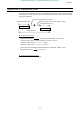
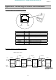
Connector diagram for 4-wire RS485 communication
Connecting diagram for 4-wire RS485 communication
* When using 2-wire type, short RXB to TXB and RXA to TXA.
* Never use pin-1 (Open) and pin-7 (P11).
Terminating resistance
120
Ω
-1/2W
Slave Slave Slave
C
N1
Master
RXA
RXB
TXA
TXB
SG
RXA
RXB
TXA
TXB
SG
RXA
RXB
TXA
TXB
SG
RXA
RXB
TXA
TXB
SG
Cross Straight
Straight
Pin-4
Pin-5
Pin-3
Pin-6
Pin-8
(
Pin-2)
Pin-1Pin-8
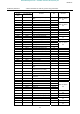
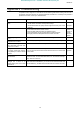
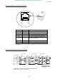
Signal name Pin number Description
RXA 4 Same phase reception data (positive line)
RXB 5 Anti-phase reception data (negative line)
TXA 3 Same phase transmitting data (positive line)
TXB 6 Anti-phase transmitting data (negative line)
SG 8
(2)
Ground line of signal data
−
1 Open (Do not connect the cable.)
P11 7 11V (Do not connect the cable.)
*This table shows signal line of inverter side. (Example: RXA signal is received by
inverter.)
E
efesotomasyon.com -Toshiba inverter,drive,servo,plc