TW12HQ3C2AI(WIFI) TW12HQ3C2DI(WIFI)
Content Operation Notices Precautions............................................................................................................ 1 Parts name ............................................................................................................ 9 Screen Operation Guide Buttons on remote controller ............................................................................... 11 Introduction for icons on display screen ..............................................................
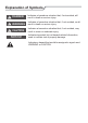
Explanation of Symbols DANGER Indicates a hazardous situation that, if not avoided, will result in death or serious injury. WARNING Indicates a hazardous situation that, if not avoided, could result in death or serious injury. CAUTION Indicates a hazardous situation that, if not avoided, may result in minor or moderate injury. NOTICE Indicates important but not hazard-related information, used to indicate risk of property damage.
Precautions WARNING Operation and Maintenance This appliance can be used by children aged from 8 years and above and persons with reduced physical, sensory or mental capabilities or lack of experience and knowledge if they have been given supervision or instruction concerning use of the appliance in a safe way and understand the hazards involved. Children shall not play with the appliance. Cleaning and user maintenance shall not be made by children without supervision.
Precautions WARNING Maintenance must be performed by qualified professionals. Otherwise, it may cause personal injury or damage. Do not repair air conditioner by yourself. It may cause electric shock or damage. Please contact dealer when you need to repair air conditioner. Do not extend fingers or objects into air inlet or air outlet. It may cause personal injury or damage. Do not block air outlet or air inlet. It may cause malfunction.
Precautions WARNING Attachment Installation must be performed by qualified professionals. Otherwise, it may cause personal injury or damage. Must follow the electric safety regulations when installing the unit. According to the local safety regulations, use qualified power supply circuit and circuit break. Do install the circuit break. If not, it may cause malfunction. An all-pole disconnection switch having a contact separation of at least 3mm in all poles should be connected in fixed wiring.
Precautions WARNING Do not put through the power before finishing installation. If the supply cord is damaged, it must be replaced by the manufacturer, its service agent or similarly qualified persons in order to avoid a hazard. The temperature of refrigerant circuit will be high, please keep the interconnection cable away from the copper tube. The appliance shall be installed in accordance with national wiring regulations.
Precautions WARNING For the air conditioner with plug, the plug should be reachable after finishing installation. For the air conditioner without plug, an circuit break must be installed in the line. If you need to relocate the air conditioner to another place, only the qualified person can perform the work. Otherwise, it may cause personal injury or damage. Select a location which is out of reach for children and far away from animals or plants.If it is unavoidable, please add the fence for safety purpose.
Precautions FCC STATEMENT (1) this device may not cause harmful interference, and (2) this device must accept any interference received,including interference that may cause undesired operation. NOTE: This equipment has been tested and found to comply with the limits for a Class B digital device, pursuant to part 15 of the FCC Rules. These limits are designed to provide reasonable protection against harmful interference in a residential installation.
Precautions IC STATEMENT This device complies with Industry Canada licenceexempt RSS standard(s). Operation is subject to the following two conditions: (1) this device may not cause interference, and (2) this device must accept any interference, including interference that may cause undesired operation of the device. Le présent appareil est conforme aux CNR d'Industrie Canada applicables aux appareils radio exempts de licence.
Precautions IC STATEMENT antennes utilisées pour cet émetteur doivent être installées et doivent fonctionner à au moins 20 cm de distance des utilisateurs et ne doivent pas être placées près d’autres antennes ou émetteurs ou fonctionner avec ceux-ci. Les installateurs doivent s’assurer qu’une distance de 20 cm sépare l’appareil (à l’exception du combiné) des utilisateurs. Working temperature range Maximum cooling Maximum heating Indoor side DB/WB(°C/°F) Outdoor side DB/WB(°C/°F) 26.7/19.4(80/66.9) 46.
Parts Name Indoor Unit air inlet panel aux.button horizontal louver air outlet remote control (Display content or position may be different from above graphics, please refer to actual products) NOTICE: Actual product may be different from above graphics, please refer to actual products.
Parts name Display For some model: For some model: cooling indicator power indicator temp. indicator heating indicator receiver window display cooling indicator heating indicator temp. indicator drying display indicator For some model: drying indicator For some model: drying indicator temp. indicator power indicator heating indicator cooling indicator receiver window power indicator Power indicatior temp. indicator display receiver window For some model: receiver window display temp.
Buttons on remote controller 2 4 ON/OFF button 2 MODE button 3 FAN button 4 SWING button 3 5 TURBO button 5 6 ▲/ 7 SLEEP button 8 TEMP button 9 WiFi button 6 7 8 9 11 10 ▲ 1 1 button 10 LIGHT button 12 11 CLOCK button 12 TIMER ON / TIMER OFF button Introduction for icons on display screen Set fan speed I feel Send signal Turbo mode Operation mode Auto mode Cool mode 8℃ heating function Set temperature Dry mode Fan mode WiFi have this function while some { models do n
Introduction for buttons on remote controller Note: ● This is a general use remote controller, it could be used for the air conditioners with multifunction; For some function, which the model doesn't have, if press the corresponding button on the remote controller that the unit will keep the original running status. ● After putting through the power, the air conditioner will give out a sound. Operation indictor is ON (red indicator, the colour is different for different models).
Introduction for buttons on remote controller ▲ Press "▲" or " " button to adjust set temperature. Press "FAN" button to adjust fan speed. Press "SWING" button to adjust fan blowing angle. (Cooling only unit won’t receive heating mode signal. If setting heat mode with remote controller, press ON/OFF button can’t start up the unit). Note: ● For preventing cold air, after starting up heating mode, indoor unit will delay 1~5 minutes to blow air (actual delay time is depend on indoor ambient temperature).
Introduction for buttons on remote controller ● When selecting " ", air conditioner is blowing fan automatically. Horizontal louver will automatically swing up & down at maximum angle. ● When selecting " 、 、 、 、 ● When selecting " 、 、 ● Hold " " button above 2s to set your required swing angle. When reaching your required angle, release the button. Note: " 、 、 " may not be available. When air conditioner receives this signal, the air conditioner will blow fan automatically.
Introduction for buttons on remote controller ● When selecting " " or no display with remote controller, temperature indicator on indoor unit displays set temperature. ● When selecting " " with remote controller, temperature indicator on indoor unit displays indoor ambient temperature. ● When selecting " " with remote controller, temperature indicator on indoor unit displays outdoor ambient temperature. Note: ● Outdoor temperature display is not available for some models.
Introduction for buttons on remote controller ● TIMER ON button "TIMER ON" button can set the time for timer on. After pressing this button, " " icon disappears and the word "ON" on remote controller blinks. Press "▲" or " "button to adjust TIMER ON setting. After each pressing "▲" or " " button, TIMER ON setting will increase or decrease 1min. Hold "▲" or " " button, 2s later, the time will change quickly until reaching your required time. ▲ ▲ ▲ resumes displaying.
Function introduction for combination buttons ● Sleep function and energy-saving function can’t operate at the same time. If energy-saving function has been set under cooling mode, press sleep button will cancel energy-saving function. If sleep function has been set under cooling mode, start up the energy-saving function will cancel sleep function. 8℃ heating function Under heating mode, press "TEMP" and "CLOCK" buttons simultaneously to start up or turn off 8℃ heating function.
Operation guide 1. After putting through the power, press "ON/OFF" button on remote controller to turn on the air conditioner. 2. Press "MODE" button to select your required mode: AUTO, COOL, DRY, FAN, HEAT. 3. Press "▲" or " " button to set your required temperature. (Temperature can’t be adjusted under auto mode). 4. Press "FAN" button to set your required fan speed: auto, low, medium and high speed. 5. Press "SWING" button to select fan blowing angle. ▲ Replacement of batteries in remote controller 1.
Emergency operation If remote controller is lost or damaged, please use auxiliary button to turn on or turn off the air conditioner. The operation in details are as below: air conditioner. When the air conditioner is turned on, it will operate under auto mode. panel aux. button WARNING: Use insulated object to press the auto button Clean and maintenance WARNING ■ Turn off the air conditioner and disconnect the power before cleaning the air conditioner to avoid electric shock.
Clean and maintenance 1 Open panel 3 Pull out the panel to a certain ● Use dust catcher or water to the water (below 45℃ (113°F)) to clean it, and then put it in a shady and cool place to dry. 2 4 panel cover tightly. WARNING ■ The filter should be cleaned every three months. If there is much dust in the operation environment, clean frequency can be increased. ■ After removing the filter, do not touch fins to avoid injury.
Clean and maintenance NOTICE: Checking before use-season 1. Check whether air inlets and air outlets are blocked. 2. Check whether circuit break, plug and socket are in good condition. 4. Check whether drainage pipe is damaged. NOTICE: Checking after use-season 1. Disconnect power supply. Notice for recovery 1. Many packing materials are recyclable materials. Please dispose them in appropriate recycling unit. 2.
Malfunction analysis General phenomenon analysis Please check below items before asking for maintenance. If the malfunction still can’t be eliminated, please contact local dealer or qualified professionals. Phenomenon Check items Solution ● Whether it's interfered severely ● Pull out the plug. Reinsert (such as static electricity,stable the plug after about 3min, and voltage)? then turn on the unit again. Indoor unit can’t receive remote controller’s signal or remote controller has no action.
Malfunction analysis Phenomenon Air conditioner can’t operate Mist is emitted from indoor unit’s air outlet Set temperature can’t be adjusted Cooling (heating) effect is not good. Check items Solution ● Power failure? ● Wait until power recovery. ● Is plug loose? ● Reinsert the plug. ● Circuit break trips off or fuse is burnt out? ● Ask professional to replace circuit break or fuse. ● Wiring has malfunction? ● Ask professional to replace it.
Malfunction analysis Phenomenon Odours are emitted Check items Solution ● Whether there’s odour source, ● Eliminate the odour source. such as furniture and cigarette, ● Clean the filter. etc. Air conditioner ● Whether there’s interference, such as thunder, wireless operates normally suddenly devices, etc.
Malfunction analysis Error Code ● When air conditioner status is abnormal, temperature indictor on indoor unit will ation of error code. Error code E5 E6 E8 H6 Troubleshooting It can be eliminated after restarting the unit. If not, please It can be eliminated after restarting the unit. If not, please It can be eliminated after restarting the unit. If not, please It can be eliminated after restarting the unit. If not, please C5 F0 F1 F2 U8 It can be eliminated after restarting the unit.
At least 15cm Space to the ceiling Installation dimension diagram Space to the wall At least 15cm At least 15cm Space to the wall Sp e ac to le the m 0c 30 on cti tru s ob At least 250cm At t as 6
Safety precautions for installing and relocating the unit To ensure safety, please be mindful of the following precautions. Warning When installing or relocating the unit, be sure to keep the refrigerant circuit free from air or substances other than the specified refrigerant. Any presence of air or other foreign substance in the refrigerant circuit will cause system pressure rise or compressor rupture, resulting in injury.
Tools for installation 1 Level meter 2 Screw driver 3 Impact drill 4 Drill head 5 Pipe expander 6 Torque wrench 7 Open-end wrench 8 Pipe cutter 9 Leakage detector 10 Vacuum pump 11 Pressure meter 12 Universal meter 13 Inner hexagon spanner Note: 14 Measuring tape ● Please contact the local agent for installation. ● Don't use unqualified power cord. Selection of installation location Basic requirement Installing the unit in the following places maycause malfunction.
Requirements for electric connection Safety precaution 1. Must follow the electric safety regulations when installing the unit. 2. According to the local safety regulations, use qualified power supply circuit and circuit break. 3. Make sure the power supply matches with the requirement of air conditioner. Unstable power supply or incorrect wiring or malfunction. Please install proper power supply cables before using the air conditioner. 4.
Installation of indoor unit Step one: choosing installation location rm it with the client. Step two: install wall-mounting frame 1. Hang the wall-mounting frame on the wall; adjust it in horizontal position with the plastic expansion particles in the holes. 3. Fix the wall-mounting frame on the wall with tapping screws (ST4.2X25TA) and . Step three: open piping hole 1. Choose the position of piping hole according to the direction of outlet pipe.
Installation of indoor unit Indoor Note: ● Pay attention to dust prevention and take relevant safety measures when opening the hole. ● The plastic expansion particles are not provided and should be bought locally. outdoor Φ55/Φ70 5-10° Step four: outlet pipe 2. When select leading out the pipe from left or right, please cut off the corresponding hole on the bottom case. 1. The pipe can be led out in the direction of right, rear right, left or rear left.
Installation of indoor unit open-end wrench union nut torque wrench pipe Hex nut diameter Tightening torque (N.m) Φ6 15~20 Φ 9.52 30~40 Φ 12 45~55 Φ 16 60~65 Φ 19 70~75 indoor pipe 4. Wrap the indoor pipe and joint of connection pipe with insulating pipe, and then wrap it with tape. insulating pipe Step six: install drain hose 1. Connect the drain hose to the outlet pipe of indoor unit. drain hose outlet pipe 2. Bind the joint with tape.
Installation of indoor unit 2. Make the power connection wire go through the cable-cross hole at the back of indoor unit and then pull it out from the front side. cable-cross hole power connection wire 3. Remove the wire clip; connect the power connection wire to the wiring terminal with wire clip. 12K、24K: N(1) 2 3 green white black red (brown) (yellow(blue) green) Outdoor unit connection 4.Put wiring cover back and then tighten the screw. 5.Close the panel.
Installation of indoor unit Step eight: bind up pipe 1. Bind up the connection pipe, power cord and drain hose with the band. indoor unit gas pipe connection pipe drain hose band indoor and outdoor power cord indoor power cord liquid pipe band 3. Bind them evenly. 4. The liquid pipe and gas pipe should be bound separately at the end. drain hose 2. Reserve a certain length of drain hose and power cord for installation when binding them.
Check after installation Items to be checked Possible malfunction The unit may drop, shake or emit noise. Have you done the refrigerant leakage test? (heating) capacity. It may cause condensation and water dripping. Is water drained well? It may cause condensation and water dripping. Is the voltage of power supply according to the voltage marked on the nameplate? It may cause malfunction or damaging the parts.
Configuration of connection pipe 1. Standard length of connection pipe ● 5m, 7.5m, 8m. 2.Min. length of connection pipe is 3m. 3.Max. length of connection pipe. Cooling capacity Max length of connection pipe Cooling capacity Max length of connection pipe 5000Btu/h (1465W) 15 24000Btu/h (7032W) 25 7000Btu/h (2051W) 15 28000Btu/h (8204W) 30 9000Btu/h (2637W) 15 36000Btu/h (10548W) 30 12000Btu/h (3516W) 20 42000Btu/h (12306W) 30 18000Btu/h (5274W) 25 48000Btu/h (14064W) 30 4.
Configuration of connection pipe Additional refrigerant charging amount for R22, R407C, R410A and R134a Diameter of connection pipe Outdoor unit throttle Liquid pipe(mm) Gas pipe(mm) Φ6 Φ9.52 or Φ12 15 20 Φ6 or Φ9.52 Φ16 or Φ19 15 50 Φ12 Φ19 or Φ22.2 30 120 Φ16 Φ25.4 or Φ31.8 60 120 Φ19 _ 250 250 Φ22.
Pipe expanding method Note: Improper pipe expanding is the main cause of refrigerant leakage. Please expand the pipe according to the following steps: A: Cut the pipe E: Expand the port ● Expand the port with expander. the distance of indoor unit and outdoor unit. ● Cut the required pipe with pipe cutter.
66129927424