
Owners Manual: AUTOMATIC FAUCETS


6
ENGLISH
Ø 1-1/8"
15/16"
Ø 3/16” (sheet metal surface)
Ø 1/4” (drywall/hollow wall)
Install the Spout (continued)
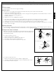
To Install Deck-Mounted Models (Ill. 2):
Secure the spout to the countertop with the included
bracket and hexagonal nut. Make sure that the spout is
mounted with the tip directed towards the center of the
basin.
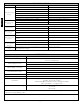
To Install Helix Wall-Mounted Models (Ill. 3 & 4):
NO TE: The addition of a 2 x 6” framing behind the
spout installation location is highly recommended.
1. Drill a ¾” (19mm) diameter hole at the spout
mounting location for the supply hose and sen-
sor cord to pass through.
2. Feed the supply hose and sensor cord through
the drilled hole and hold the mounting bracket
against the wall in the desired position. Mark
the location of the mounting bracket holes and
remove the spout.
3. Drill a 3/16” (5mm) diameter holes at the
marked locations and install the included wall
anchors. Fasten the spout securely to the wall
anchors with the provided Phillips screws.
4. Tighten the 3 small Phillips screws that secure
the spout to the mounting bracket, then hand-
tighten the escutcheon to the bracket.
To Install Gooseneck Wall-Mounted Models (Ill. 5, 6 & 7):
NO TE: The addition of a 1 x 6” or plywood
bracing behind the mounting location is highly
recommended for drywall/hollow wall installations.
The overall maximum wall thickness is 2” (50mm).
1. Drill a 1-1/8” (29 mm) hole at the desired loca-
tion for the mounting bracket. Put the mounting
bracket through a hole in the wall with the set
screw hole located at 12 o’clock. Mark the loca-
tion of the set screw hole on the wall and remove
the mounting bracket.
For sheet metal surface: Drill a 3/16” (4.8 mm) hole at
the marked location.
NO TE: Drill bits (not supplied) for hard materials
may be required.
For a drywall/hollow wall surface: Drill a 1/4”
(6.5 mm) hole at the marked location, and install the
included wall anchors.
NO TE: Confi rmation of wall strength is highly
recommended before drilling.
2. Install the mounting bracket using the rubber
washer, brass washer, and both brass nuts
on back side of the installation surface.
Install the included set screw (for sheet metal
installation) or 30 mm machine screw (for drywall
installations).
3. Pass the hose and sensor cord through the
mount¬ing bracket, slide the spout base over
the mounting bracket and tighten the set screw
to secure the spout to the mounting bracket.
Drain
Drain
Spout
Spout
Basin Center
Basin Center
SPOUT POSITION
IN THE CENTER
SPOUT POSITION
ON THE RIGHT
Ill. 2
2 x 6
Framing
2 x 4
Studs
Finished Wall
3/4” Diameter
Hole for Anchors
3/16” Diameter
Holes for Anchors
Ill. 3
Ill. 4
Escutcheon
Set Screw
(Sheet metal) or
Machine Screw
(Drywall/ Hollow
Wall)
Rubber Washer
Brass Washer
Nuts (2)
Ill. 5
M5x30
Machine
Screw
and
Wall
Anchor
Ill. 6
Ill. 7
Set Screw
Mounting
Bracket
M5 Set
Screw
1x6 or Plywood
Bracing
Set Screw
Sheetmetal InstallationDrywall Installation
Mounting
Bracket
Hole for set screw/machine
screw and wall
anchor
Hole for mounting bracket
Plywood
(not required for sheet
metal installation)
Thin Wall
(Sheet
Metal
Surface)
Drywall